EP0045973A2 - Shock absorber - Google Patents
Shock absorber Download PDFInfo
- Publication number
- EP0045973A2 EP0045973A2 EP19810106291 EP81106291A EP0045973A2 EP 0045973 A2 EP0045973 A2 EP 0045973A2 EP 19810106291 EP19810106291 EP 19810106291 EP 81106291 A EP81106291 A EP 81106291A EP 0045973 A2 EP0045973 A2 EP 0045973A2
- Authority
- EP
- European Patent Office
- Prior art keywords
- vortex
- chamber
- fluid
- piston
- shock absorber
- Prior art date
- Legal status (The legal status is an assumption and is not a legal conclusion. Google has not performed a legal analysis and makes no representation as to the accuracy of the status listed.)
- Granted
Links
Images


Classifications
-
- F—MECHANICAL ENGINEERING; LIGHTING; HEATING; WEAPONS; BLASTING
- F16—ENGINEERING ELEMENTS AND UNITS; GENERAL MEASURES FOR PRODUCING AND MAINTAINING EFFECTIVE FUNCTIONING OF MACHINES OR INSTALLATIONS; THERMAL INSULATION IN GENERAL
- F16F—SPRINGS; SHOCK-ABSORBERS; MEANS FOR DAMPING VIBRATION
- F16F9/00—Springs, vibration-dampers, shock-absorbers, or similarly-constructed movement-dampers using a fluid or the equivalent as damping medium
- F16F9/32—Details
- F16F9/34—Special valve constructions; Shape or construction of throttling passages
- F16F9/344—Vortex flow passages
-
- B—PERFORMING OPERATIONS; TRANSPORTING
- B60—VEHICLES IN GENERAL
- B60G—VEHICLE SUSPENSION ARRANGEMENTS
- B60G13/00—Resilient suspensions characterised by arrangement, location or type of vibration dampers
- B60G13/02—Resilient suspensions characterised by arrangement, location or type of vibration dampers having dampers dissipating energy, e.g. frictionally
- B60G13/06—Resilient suspensions characterised by arrangement, location or type of vibration dampers having dampers dissipating energy, e.g. frictionally of fluid type
- B60G13/08—Resilient suspensions characterised by arrangement, location or type of vibration dampers having dampers dissipating energy, e.g. frictionally of fluid type hydraulic
-
- Y—GENERAL TAGGING OF NEW TECHNOLOGICAL DEVELOPMENTS; GENERAL TAGGING OF CROSS-SECTIONAL TECHNOLOGIES SPANNING OVER SEVERAL SECTIONS OF THE IPC; TECHNICAL SUBJECTS COVERED BY FORMER USPC CROSS-REFERENCE ART COLLECTIONS [XRACs] AND DIGESTS
- Y10—TECHNICAL SUBJECTS COVERED BY FORMER USPC
- Y10T—TECHNICAL SUBJECTS COVERED BY FORMER US CLASSIFICATION
- Y10T137/00—Fluid handling
- Y10T137/206—Flow affected by fluid contact, energy field or coanda effect [e.g., pure fluid device or system]
- Y10T137/2087—Means to cause rotational flow of fluid [e.g., vortex generator]
- Y10T137/2093—Plural vortex generators
-
- Y—GENERAL TAGGING OF NEW TECHNOLOGICAL DEVELOPMENTS; GENERAL TAGGING OF CROSS-SECTIONAL TECHNOLOGIES SPANNING OVER SEVERAL SECTIONS OF THE IPC; TECHNICAL SUBJECTS COVERED BY FORMER USPC CROSS-REFERENCE ART COLLECTIONS [XRACs] AND DIGESTS
- Y10—TECHNICAL SUBJECTS COVERED BY FORMER USPC
- Y10T—TECHNICAL SUBJECTS COVERED BY FORMER US CLASSIFICATION
- Y10T137/00—Fluid handling
- Y10T137/206—Flow affected by fluid contact, energy field or coanda effect [e.g., pure fluid device or system]
- Y10T137/2087—Means to cause rotational flow of fluid [e.g., vortex generator]
- Y10T137/2098—Vortex generator as control for system
-
- Y—GENERAL TAGGING OF NEW TECHNOLOGICAL DEVELOPMENTS; GENERAL TAGGING OF CROSS-SECTIONAL TECHNOLOGIES SPANNING OVER SEVERAL SECTIONS OF THE IPC; TECHNICAL SUBJECTS COVERED BY FORMER USPC CROSS-REFERENCE ART COLLECTIONS [XRACs] AND DIGESTS
- Y10—TECHNICAL SUBJECTS COVERED BY FORMER USPC
- Y10T—TECHNICAL SUBJECTS COVERED BY FORMER US CLASSIFICATION
- Y10T137/00—Fluid handling
- Y10T137/206—Flow affected by fluid contact, energy field or coanda effect [e.g., pure fluid device or system]
- Y10T137/212—System comprising plural fluidic devices or stages
Definitions
- the present invention relates generally to a hydraulic shock absorber for absorbing shock applied thereto and is applicable to a vehicle suspension for example. More particularly, the invention relates to an improvement for a vortex shock absorber with variable absorbing force depending not only on the piston speed but also on the piston stroke, and with simple construction for assembly.
- the vortex shock absorbers have been well-known as applied to vehicle suspensions, for example.
- a piston slidably received within a cylinder is provided with a vortex chamber therein.
- the piston defines upper and lower chambers within the cylinder.
- the vortex chamber is communicated with the upper and lower chambers via a vortex passage tangentially opening thereinto so that the fluid flow introduced therein generates a vortex for producing the absorbing force.
- the absorbing force produced by the shock absorber varies depending on the piston speed in response to the shock.
- shock absorber In case of the shock absorber being applied to the suspension of an automotive vehicle, it is preferable to provide a relatively small absorbing force against relatively small piston stroke, even though piston speed is relatively high, for riding comfort. On the other hand, for a relatively large piston stroke, a relatively large absorbing force is required for vehicle stability. Therefore, a shock absorber for use with the automotive vehicle suspension is required to vary the absorbing force against shock depending not only on piston speed but also on piston stroke.
- the piston is formed with one or more vortex passages.
- the vortex passage comprises vertical and horizontal sections formed in the periphery of the piston.
- the periphery of the piston must be sufficiently thick. This places a lower limit on the volume of the piston and in turn on the volume of the shock absorber.
- Another object of the invention is to provide a shock absorber varying the absorbing force depending not only on the piston speed but also on the piston stroke.
- a shock absorber having a piston which comprises upper and lower members.
- the upper and lower members are fixedly assembled to define therein the vortex chamber.
- the piston has vertically-extending channels on the outer periphery thereof to define the vertical section of the vortex passage in conjunction with the inner periphery of the cylinder tube.
- a hydraulic shock absorber comprising a hollow cylinder defining therein a fluid chamber filled with a working fluid, a piston slidably disposed within the fluid chamber to divide the fluid chamber into upper and lower chambers and having first and second members assembled together for defining therein a vortex chamber, the upper and lower members being formed with a vertically-extending recess on the outer periphery thereof.
- the recesses formed in the upper and lower members are aligned with respect to each other and define vertical fluid passages.
- the piston further defines vortex passages, having inner ends tangentially opening toward the vortex chamber and outer ends opening toward the vertical passages, and a means for establishing communication between the upper and lower chambers and the vortex chamber.
- the shock absorber comprises a hollow cylinder 30 and a piston 32 movably disposed within the cylinder 30.
- the piston 32 is secured on the lower end of a piston rod 34 which has an upper end extending out of the cylinder 30 and attached to a vehicle body chassis (not shown).
- the lower end of the cylinder 30 is attached to a wheel axle (not shown).
- a free piston 36 with annular sealing ring 38 is also movably disposed within the tube to . define within the cylinder 30 a pneumatic chamber 40.
- a chamber 42 defined within the cylinder tube 30 and being filled with a working fluid is divided into upper and lower chambers 44 and 46 respectively by the piston 32.
- the piston 32 comprises upper and lower predominately disc-shaped members 48 and 50 respectively formed with horizontally-oriented circular recesses 52 and 54 respectively.
- the upper and lower members are formed with recesses 56 and 58 respectively on the circumferences thereof.
- Vortex passages 64 and 66 are defined in the piston 32 such that the outer ends of the vortex passages 64 and 66 open toward the recesses 56 and 58 respectively and the inner ends thereof open toward the recesses 52 and 54 respectively.
- the inner ends of the vortex passages 64 and 66 are directed along the circumference of the recesses 52 and 54 respectively.
- a disc-shaped plate 67 is interposed between the upper and lower members 48 and 50.
- the plate 67 has a diameter substantially equal to that of the recesses 56 and 58.
- the planes having the recesses 52 and 54 face each other.
- the plate 67 is mounted within the recesses 52 and 54.
- the upper and lower members 48 and 50 are secured one another.
- the assembled piston 32 defines upper and lower vortex chambers 68 and 70, respectively, therein. Also, the piston 32 has vertical vortex passages 72 on its circumference, which are defined by the internal periphery of the cylinder 30 and the recesses 56 and 58. The vertical vortex passages 72 establish communication between the vortex passages 64 and 66.
- the upper member 48 of the piston 32 is provided with a projecting portion 74 with a threaded bore 76 on the surface facing the piston rod 34.
- the piston rod 34 has a threaded portion 78 at the lower end thereof.
- the threaded portion 78 engages with the threaded bore 76 for attaching the piston 32 onto the lower end of the piston rod 34.
- a dish-shaped member 80 is mounted on the top of the projecting portion 74 and secured thereto by engagement of the threaded portion 78 and the threaded bore 76.
- a pair of radial passages 84 extend radially through the projecting portion 74.
- the outer ends of the passages 84 open into the upper fluid chamber 44 at the circumference of the projecting portion 74 and the inner ends thereof open toward the threaded bore 76.
- the threaded bore 76 in turn, communicates with the upper vortex chamber 68 via an opening 86.
- the lower member 50 of the piston 32 is formed with an opening 88 in its central portion for communication between the lower vortex chamber 70 and the lower fluid chamber 46.
- vortex passages 64 and 66', and the fluid passages 84 have diameters small -enough to limit the fluid flow therethrough and, therefore, are adapted to serve as orifices.
- the effective area So(given in mm 2 ), which serves to vary the relative volumes of the upper and lower chambers 44 and 46, and the horizontal cross-sectional area Sv(given in mm2) of the upper and lower vortex chambers 68 and 70 can be obtained from the following equations respectively:
- the dimensions of piston 32 are such that the relationship between the effective area So and the horizontal cross-sectional area S v of the vortex chambers 68 and 70 can be represented by: where h is the height in mm of each of the vortex chambers 68 and 70
- the above-specified dimensional relationship can be applied to any hydraulic shock absorber absorbing shock by generating a vortex. Therefore, the specific construction of the shock absorber gives no limitation to the present invention in any way. Furthermore, it should be noted that the present invention is designed in accordance with the dimensional relationship of the areas serving to vary the volume of the chambers 44 and 46 and serving to generate a vortex in the vortex chambers 68 and 70.
- the volume of the lower fluid chamber 46 is reduced corresponding to the downward movement of the piston 32 to increase the fluid pressure therein.
- the downward movement of the piston 32 decreases the fluid pressure in the upper fluid chamber 44 due to expansion of the volume of that chamber. Due to the pressure difference between the upper and lower fluid chamber, the fluid in the lower fluid chamber flows into the lower vortex chamber 70 via the opening 88.
- the fluid in the lower chamber 46 flows into the upper chamber 44 via the piston 32.
- the fluid in the chamber 46 enters the lower vortex chamber through the opening 88.
- the fluid flows via the lower vortex chamber 70, the vortex passage 64, the vertical vortex passage 72 and the vortex passage 62 into the upper vortex chamber 68.
- the fluid is discharged into the upper chamber 68 along a tangent to the circle of the upper vortex chamber 68 in order to produce a vortex therein.
- the fluid flows into the upper chamber 44 via the opening 86 and the passages 84.
- the fluid passages 84 serve as orifices to limit the flow therethrough.
- the vortex passages 64 and 66 limit the flow of the fluid therethrough to produce resistance against the fluid flow.
- the piston stroke is relatively small, the resistance against the fluid flow produced by the vortex in the upper vortex chamber 68 is insufficient to absorb the shock.
- the fluid passages 84 and the vortex passages 64 and 66 serve to provide resistance against the fluid flow at this time.
- the absorbing force against the shock which, in turn, corresponds to the resistance against the fluid flow, is mainly produced by the orifice effect provided by the fluid passage 84 and the vortex passages 64 and 66.
- the resistance against the fluid flow provided by the vortex in the upper vortex chamber 68 becomes sufficient to absorb the shock.
- the threshold where the piston stroke becomes great enough to absorb the shock is determined by the dimensional relationship between the effective cross-sectional area of the piston and the cross-sectional area of the vortex chamber.
- the threshold is set in a range of approximately 5 mm to 30 mm of piston stroke, in consideration of the various vehicle driving conditions.
- the volume of the upper chamber 44 is reduced and the volume of the lower chamber 46 is increased to induce fluid flow via the piston 32.
- the vortex is produced in the lower vortex chamber 70 in order to generate the shock absorbing force.
- FIG. 5 to 7 show a modification of the foregoing first embodiment of the invention. Since the most parts of this modification are substantially same as that of the foregoing, the reference numerals given to the corresponding parts which have the same construction and the same function are the same as in the preceeding embodiment to avoid repetition of the description. Therefore, the parts. not illustrated herebelow should be understood as being the same as in the preceding description.
- the piston 32 of the present modification comprises upper and lower members 48 and 50 and defines therein upper and lower vortex chambers 68 and 70.
- the lower member 50 is formed with a plurality of apertures 90 extending in parallel with the axis of the piston 32.
- the upper member is also formed with a plurality of threaded bores 92 extending in parallel with the axis of the piston.
- the apertures 90 and the threaded bores 92 are located to align with one another upon assembly of the piston.
- a plurality of screws 94 extend through apertures 90 and engage with threaded bores 92 for securing the upper and lower members 48 and 50 of the piston in the assembled position.
- the projecting portion 74 has the threaded bore 76.
- the threaded bore 76 receives the threaded portion 78 of the piston rod 34 for attaching the piston onto the lower end of the piston rod 34.
- the threaded portion 78 is formed with an angled duct 96.
- the vertical section -of - the angled duct 96 extends along the longitudinal axis of the piston rod 34 and opens toward the lower end thereof.
- the lateral section of the angled duct 96 extends radially to open at the periphery of the piston rod.
- the vertical section of the angled duct 96 is aligned with the opening 88.
- the upper fluid chamber 44 and the upper vortex chamber 68 communicate via the angled duct 96 and the opening 86.
- Figs. 8 to 10 show a further modification of the shock absorber of Fig. 1.
- the common parts which are not modified are represented by the common reference numerals.
- a tube 98 is inserted into the vortex passages 64, 66 and 72.
- the tube 98 is. angled near both ends thereof to define vertical and lateral sections.
- the vertical section of the tube 98 is disposed within the vertical vortex passage 72 and the horizontal sections extend through the vortex passages 64 and 66.
- the vertical vortex passage 72 is defined by the vertically extending recesses on the circumference of the piston 32 and a cylindrical sleeve 100 mounted on the circumference.
- the vortex chambers 68 and 70 are connected via the tube 98 arranged along the vortex passages 64, 66 and 72.
- the tube 98 serves to conduct the fluid smoothly between the upper and lower vortex chambers 68 and 70.
- FIG. 12 is a graph showing the relationship between the absorbing force and the piston speed of the above-described modifications of Figs. 8 to 10, which can be compared with that produced by the conventional vortex shock absorber.
- the absorbing force against shock causing a relatively small piston stroke can be smaller than that of a conventional shock absorber. This makes the vehicle suspension respond more gently to provide a more comfortable ride.
- the absorbing force produced by the shock absorber can be increased to ensure greater stability for the vehicle.
- the absorbing force is varied depending on not only the piston speed but also the piston stroke.
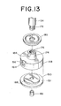
- FIG. 13 to 15 there is illustrated the second embodiment of a shock absorber according to the present invention.
- a piston 132 is movably disposed within a chamber 142 defined in a cylinder 130.
- the piston 132 divides the chamber 142 into upper and lower fluid chambers 144 and 146.
- the piston comprises an upper member 148 and a lower member 150 engageable with one another.
- the upper member 148 is formed with a circular recess 152 in the lower surface thereof.
- the upper member 148 is formed with a pair of vertically-extending recesses 156 and 157 on its periphery. In the shown embodiment, the recesses 156 and 157 are located in alignment on the diametric line of the upper member 148.
- the recess 156 opens into upper fluid chamber 144 at the upper end thereof and the recess 157 opens into the lower fluid chamber 146 at the lower end thereof.
- the recesses 156 and 157 communicate with the recess 152 via vortex passages 164.
- the vortex passages 164 extend through the upper member 148 and open to the recess 152 at the inner ends and to the recesses 156 or 157 at the outer ends.
- the inner ends of the vortex passages 164 are aligned tangentially to the circle of the recess 152.
- the upper member 148 is further provided with a cylindrical projecting portion 174 with a threaded bore 176 on the upper surface thereof.
- the threaded bore 176 receives a threaded end portion 178 of a piston rod 134 for attaching the piston 132 on to the lower end of the piston rod 134.
- a dish shaped member 180 is mounted on the top of the projecting portion 174 and secured thereon by engagement of the threaded bore 176 and the threaded end portion 178.
- a plurality of narrow passages 184 extend radially through the projecting portion 174 to open toward the threaded bore 176 at the inner ends thereof and into the upper fluid chamber 144 at their outer ends.
- the threaded bore 176 communicates with the recess 152 via a vertical passage 186.
- the lower member 150 is disc-shaped and formed with an annular cut-out 151 along the circumference of the upper plane surface.
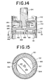
- the cut-out 151 is engageable with the lower surface of the upper member 148, as shown in Fig. 14.
- the lower member 150 is also formed with a vertically-extending opening 188 through the central portion thereof.
- a cylindrical pipe 189 is disposed within the opening 188 for reducing the cross-sectional area of the latter.
- the upper and lower members 148 and 150 are assembled together to constitute the piston 132. Upon assembly, the lower member 150 is secured onto the lower surface of the upper member 148 by any suitable means, such as with screws. In the assembled condition, the recess 152 is closed by the lower member 150 to define the vortex chamber 168.
- the piston 132 moves upwards to reduce the volume of the upper fluid chamber 144 and thereby to increase the fluid pressure in the upper fluid chamber 144.
- the volume of the lower fluid chamber 146 is increased to reduce the fluid pressure in the lower chamber 146. Due to the fluid pressure difference between the upper and lower fluid chamber 144 and 146, the fluid in the upper chamber 144 flows to the lower chamber 146 via the vortex chamber 168 to equalize the fluid pressure. At this case, the fluid in the upper fluid chamber 144 flows into the vortex chamber 168 through the fluid passages 184 and 186, and through the recess 156 and the vortex passage 164.
- the fluid passage 184 has relatively small cross-sectional area, the fluid flow therethrough is limited.
- the fluid flowing into the vortex chamber 168 via the vortex passage 156 is discharged toward the circumference of the vortex chamber to produce the vortex therein.
- the vortex in the vortex chamber 168 also limits the flow of the fluid therethrough. If the piston stroke is relatively small, the resistance against the fluid flow provided by the vortex is insufficient to provide rigidity for the shock absorber. Therefore, against a shock causing a relatively small piston stroke, resistance against the fluid flow in the fluid passages 184 provides most of the absorbing force. Furthermore, the area of the opening 188 reduced by the pipe 189 will serve as an orifice to produce resistance against the fluid flow. As the piston stroke increases, resistance due to the vortex becomes a major part of the absorbing force provided by the shock absorber.
- Fig. 16 shows variation of the absorbing force with respect to the piston speed.
- the absorbing force produced in response to relatively short piston stroke depends mainly on the the resistance provided by the orifice effect of the passage 184 and the opening 188. ' Therefore, the absorbing force against a shock resulting in a relatively small piston stroke can be sufficiently reduced for riding comfort.
- the shock causes relatively great piston stroke, the resistance of the vortex against the fluid flow is sufficiently increased to produce greater absorbing force.
- Figs. 17 and 18 shows a modification of the foregoing second embodiment of the present invention.
- the parts constructed similar to that of the foregoing and having the same function will be represented by the same reference numerals.
- the piston 132 comprises upper and lower members 148 and 150.
- the upper member 148 has a projecting portion 174 on its upper surface.
- the projecting portion 174 is formed with a axially-extending threaded bore 176 with a stepped lower section 190.
- the lower section 190 is in communication with the vertical fluid passage 186.
- the threaded portion 178 of the piston rod 134 engages with the threaded bore 176 for attaching the piston 132 onto the lower end of the piston rod 134.
- the threaded portion 178 of the piston rod 134 and the threaded bore 176 define a fluid flow space 192 with the stepped section 190 of the threaded bore.
- a ball-shaped valve member 194 is disposed within the space 192.
- the stepped section 190 of the threaded bore 176 serves as the valve seat of the valve member 1 94 .
- the lower member 150 is provided with a projecting portion 196 on the lower surface thereof.
- the opening 188 extends through the major portion and the projecting portion 196 of the lower member 150.
- the opening 188 has an enlarged conical lower section 198.
- a retainer plate 200 with a plurality of vertically extending apertures 202 is attached onto the lower end of the projecting portion 196. The retainer plate 200 thus closes the lower end of the through opening 188 but maintains communication between the opening 188 and the lower fluid chamber 146 via the apertures 202.
- a ball-shaped valve member 204 is disposed within the conical lower section 198 of the opening 188. For the valve member 204, the upper end of the conical lower section 198 serves as the valve seat.
- the valve member 194 is urged onto the valve seat 190 to block communication between the upper fluid chamber 144 and the vortex chamber 168, and the fluid in the upper fluid chamber 144 flows into the vortex chamber 168 only via the vortex passages 164.
- the vortex generated in the vortex chamber 168 creates greater resistance against the fluid flow. Since the vortex provides greater resistance than that provided by the fluid passage 184, the absorbing force against this shock becomes considerably greater than that against the shock causing a relatively small piston stroke.
- the fluid flow created by the downward piston motion and flowing through the opening 188 urges the valve member 204 toward the upper end of the conical lower section 198. If the piston stroke is relatively small, the flow is small. The valve member 204 still permits flow between the lower fluid chamber 146 and the vortex chamber 168. At this time, since the flow into the vortex chamber 168 via the vortex passage 164 is too small to generate the vortex, the resistance against the fluid flow provided by the space between the valve member 204 and the upper end of the lower-section 198 provides most of the shock abosrbing force.
- the valve member 204 is seated onto the upper end of the lower section 198 to block communication between the lower fluid chamber 146 and the vortex chamber 168, the fluid in the lower fluid chamber 146 flows into the vortex chamber 170 only via the vortex passage 164. In this case, the vortex is generated in the vortex chamber 168 to create resistance against the fluid flow. Since the vortex provides greater resistance than that provided by the orifice effect of the space between the valve member 204 and the upper end of the lower section 198, the absorbing force against this shock becomes considerably greater than that against the shock causing a relatively small piston stroke.
- Fig. 19 shows variation of the absorbing force with respect to the piston speed. As apparent from Fig. 19, the absorbing force produced by the shock absorber of Figs. 17 and 18 depends on not only the piston speed but also the piston stroke.
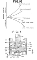
- Figs. 20 and 21 show another modification of the second embodiment of the present invention.
- the upper and lower members of the piston 148 and 150 in assembled position define the vortex chamber 168 in the piston 132.
- An elastic partitioning member 210 is disposed within the vortex chamber 168 to divide the vortex chamber 168 into . the upper and lower sections 212 and 214.
- a pair of vertically-extending recesses 216 is formed on the periphery of the upper member 148.
- the recess 21 6 communicates with upper and lower sections 212 and 214 of the vortex chamber 168 via the vortex passages 218 and 220, respectively.
- the partitioning member 210 is formed with tangentically-extending opening 222 on the vertical portion 224 thereof, which engages with an annular recess 226 formed on the inner circumferential periphery of the lower member 150.
- the upper member 148 of the piston 132 is provided with the projecting portion 174 with a threaded bore 176.
- the threaded bore 176 communicates with the upper section 212 of the vortex chamber 168 via the vertical fluid passage 186.
- the vertical fluid passage 186 communicates with the upper fluid chamber (not clearly shown) via an angled duct. 228 having a vertical section extending through the threaded portion 178 of the piston rod 134 and a horizontal section opening into the upper fluid chamber 144 at the periphery of the piston rod 134.
- the elastic partitioning member 210 is formed of an elastic rubber. However, this can be formed of any suitable material such as synthetic resin, spring steel and so on.
- the partitioning member 210 In operation, according to the fluid flow from the upper fluid chamber 144 to the lower fluid chamber 146 or from the lower fluid chamber 146 to the upper fluid chamber 144 via the vortex chamber 168, the partitioning member 210 is deformed due to the fluid pressure applied thereto to absorb the pressure.
- the partitioning member 210 deforms to the elastical limit thereof and works as a rigid partition after deformation to" the,'elastical limit. Therefore, if the piston stroke in response to the shock applied is small, the pressure of fluid flow is absorbed by the partitioning member 210. In this case, the vortex produces no absorbing force against the shock. If the piston stroke is great enough to deform the partitioning member to the rigid state, the shock is absorbed by the function of the vortex in substantially the same manner as illustrated in foregoing embodiment of Figs. 5 to 7.
- Fig. 22 shows variation of the absorbing force produced by the foregoing shock absorber of Figs. 20 and 21 with respect to the piston speed. As seen from Fig. 22, the absorbing force depends on not only the piston speed but also the piston stroke.
- the upper and lower members of the piston 148 and 150 in assembled position define the vortex chamber 168 in the piston 132.
- An elastic partitioning member 210 is disposed within the vortex chamber 168 to divide the vortex chamber 168 into the upper and lower sections 212 and 214.
- a pair of vertically-extending recesses 216 is formed on the periphery of the upper member 148. The recess 216 communicates with upper and lower sections 212 and 214 of the vortex chamber 168 via the vortex passages 218 and 220, respectively.
- the partitioning member 210 is formed with tangentially-extending opening 222 on the vertical portion 224 thereof, which engages with an annular recess 226 formed on the inner periphery of the lower member 150.
- the upper member 148 of the piston 132 is provided with a projecting portion 174 with a threaded broe 176.
- the threaded bore 176 communicates with the upper section 212 of the vortex chamber 168 via the vertical fluid passage 186.
- the vertical fluid passage 186 communicates with the upper fluid chamber (not clearly shown) via an angled duct 228 having a vertical section extending through the threaded portion 178 of the piston rod 134 and a horizontal section opening into the upper fluid chamber 144 at the periphery of the piston rod 134.
- the partitioning member 210 is provided with a relief valve 230.
- the relief valve 230 comprises a pair of disc-shaped elastic plates 232 and 234 made of elastic material such as spring steel.
- the plates 232 and 234 are attached onto both surfaces of the partitioning member 210 with a fastening member 236 such as a rivet, in the central portion thereof.
- the partitioning member 210 is formed with a plurality of apertures 238 and 240 which extend vertically.
- the plate 232 is formed with a plurality of openings 242 in axial alignment with the openings 238.
- the plate 234 is formed with a plurality of openings 244 in alignment with the opening 240.
- the plates 2 3 2 and 234 define a set pressure for the relief valve 230, maintaining the latter in a closed state until the fluid pressure applied thereto exceeds the set pressure.
- the partitioning member 210 serves to absorb the fluid flow in the vortex chamber as illustrated in foregoing embodiment of Figs. 21 and 22.
- the relief valve 230 is normally in the closed state.
- the relief valve 230 opens to permit fluid flow therethrough when the fluid pressure in one of the section of the vortex chamber 168 becomes greater than that of the set value.
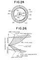
- the relief valve 230 prevents the shock absorber from producing excessive absorbing force, as shown in Fig. 26.
- the hatched area represents the range where the shock absorber works to absorb force depending on the piston stroke and the piston speed.
Abstract
Description
- The present invention relates generally to a hydraulic shock absorber for absorbing shock applied thereto and is applicable to a vehicle suspension for example. More particularly, the invention relates to an improvement for a vortex shock absorber with variable absorbing force depending not only on the piston speed but also on the piston stroke, and with simple construction for assembly.
- The vortex shock absorbers have been well-known as applied to vehicle suspensions, for example. In such a shock absorber, a piston slidably received within a cylinder is provided with a vortex chamber therein. The piston defines upper and lower chambers within the cylinder. The vortex chamber is communicated with the upper and lower chambers via a vortex passage tangentially opening thereinto so that the fluid flow introduced therein generates a vortex for producing the absorbing force. Conventionally, the absorbing force produced by the shock absorber varies depending on the piston speed in response to the shock.
- In case of the shock absorber being applied to the suspension of an automotive vehicle, it is preferable to provide a relatively small absorbing force against relatively small piston stroke, even though piston speed is relatively high, for riding comfort. On the other hand, for a relatively large piston stroke, a relatively large absorbing force is required for vehicle stability. Therefore, a shock absorber for use with the automotive vehicle suspension is required to vary the absorbing force against shock depending not only on piston speed but also on piston stroke.
- In general, the piston stroke corresponding to various vehicle driving conditions are approximated as follows:

- As understood hereabove, when the vehicle is turned abruptly, rapidly accelerated, or changes lanes, a significant absorbing force is required for adequate driving stability. On the other hand, when the vehicle is driven over a slight bump, on a smooth road, or on a relatively rough road, a significant absorbing force is not required since the vehicle is easily maintained in a stable condition. In the latter driving condition, it is important to provide minimal absorbing force for riding comfort.
- Meanwhile, for communication between the upper and lower fluid chambers, defined opposite the upper and lower sides of the piston, and the vortex chamber, the piston is formed with one or more vortex passages. Generally, the vortex passage comprises vertical and horizontal sections formed in the periphery of the piston. To provide for the vortex passages, the periphery of the piston must be sufficiently thick. This places a lower limit on the volume of the piston and in turn on the volume of the shock absorber.
- Furthermore, in the conventional shock absorber, since the vertical and horizontal sections of the vortex passages are formed integrally in the periphery of the piston, the vortex passages make machining of the piston more difficult.
- Therefore, it is an principle object of the present invention to provide a shock absorber designed for easy manufacturing and in which the thickness of the periphery of the piston is reduced.
- Another object of the invention is to provide a shock absorber varying the absorbing force depending not only on the piston speed but also on the piston stroke.
- To accomplish the above-mentioned and other objects, there is provided a shock absorber, according to the present invention, having a piston which comprises upper and lower members. The upper and lower members are fixedly assembled to define therein the vortex chamber. The piston has vertically-extending channels on the outer periphery thereof to define the vertical section of the vortex passage in conjunction with the inner periphery of the cylinder tube.
- To accomplish the above-mentioned and other objects, there is provided, according to the present invention, a hydraulic shock absorber comprising a hollow cylinder defining therein a fluid chamber filled with a working fluid, a piston slidably disposed within the fluid chamber to divide the fluid chamber into upper and lower chambers and having first and second members assembled together for defining therein a vortex chamber, the upper and lower members being formed with a vertically-extending recess on the outer periphery thereof. The recesses formed in the upper and lower members are aligned with respect to each other and define vertical fluid passages. The piston further defines vortex passages, having inner ends tangentially opening toward the vortex chamber and outer ends opening toward the vertical passages, and a means for establishing communication between the upper and lower chambers and the vortex chamber.
- The present invention will be more fully understood from the detailed description given herebelow and from the accompanying drawings of the embodiments of the present-invention, which, however, should not be understood as limitative to the invention but are for- elucidation and explanation only.
- In the drawings:
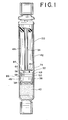
- Fig. 1 is a longitudinal cut-away view of a first embodiment of a hydraulic shock absorber in accordance with the present invention;
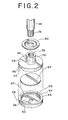
- Fig. 2 is an enlarged and exploded perspective view of a piston included in the shock abosrber of Fig. 1;
- Fig. 3 is an enlarged cross-section of the piston of Fig. 2 in assembled position;
- Fig. 4 is transverse cross-section of the piston of Fig. 2 taken along line 4 - 4 of Fig. 3;
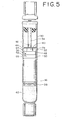
- Fig. 5 is a longitudinal cut-away view of a modification of the shock absorber of Fig. 1;
- Fig. 6 is an enlarged cross-section of the piston included in the shock absorber of Fig. 5;
- Fig. 7 is an enlarged transverse cross-section of the piston of Fig. 6 taken along line 7 - 7 of Fig. 6;
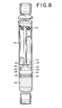
- Fig. 8 is a longitudinal cut-away view of a further modification of the shock absorber of Fig. 1;
- Fig. 9 is an enlarged cross-section of the piston included in the shock absorber of Fig. 8;
- Fig. 10 is an enlarged transverse cross-section of the piston of Fig. 9 taken along line 10 - 10 of Fig. 9;
- Fig. 11 is a further enlarged perspective view of a vortex passage for communication between upper and lower vortex chambers formed in the piston of Fig. 9;
- Fig. 12 is a graph showing variation of absorbing force with respect to variation of the speed of the piston, wherein the variation of the absorbing force in the shock absorber of Fig. 8 is represented by solid lines and the variation of the absorbing force in the conventional one is represented by broken lines;
- Fig. 13 is an exploded perspective view of the second embodiment of the piston of the shock absorber according to the present invention;
- Fig. 14 is a longitudinal cross-section of the piston of Fig. 13;
- Fig. 15 is a transverse cross-section of the piston of Fig. 13 taken along line 15 - 15 of Fig. 13;
- - Fig. 16 is a graph showing variation of the absorbing force of the shock absorber of Fig. 13 with respect to variation of the speed of the piston;
- Fig. 17 is a longitudinal cross-section of a modification of the shock absorber of Fig. 13;
- Fig. 18 is a transverse cross-section of the cylinder of Fig. 18 taken along line 18 - 18 of Fig. 17;
- Fig. 19 is a graph showing the relationship between the absorbing force produced by the shock absorber of Fig. 17 and the speed of the piston;
- Fig. 20 is a longitudinal cross-section of a further modification of the shock absorber of Fig. 13;
- Fig. 21 is a transverse cross-section of the piston od Fig. 20 taken along line 21 - 21 of Fig. 20;
- Fig. 22 is a graph showing the relationship between the absorbing force and piston speed of the shock absorber of Fig. 20;
- Fig. 23 is a longitudinal cross-section of a still further modification of the shock absorber of Fig. 13;
- Fig. 24 is a transverse cross-section of the piston of Fig. 23 taken along line 24 - 24 of Fig. 23;
- Fig. 25 is an enlarged partial cross-section showing detail of the relief valve employed in the shock absorber of Fig. 23; and
- Fig. 26 is a graph showing the absorbing force variation with respect to variation of the speed of-the piston, wherein the hatched areas show the working range of the shock absorber of Fig. 23.
- Referring now to the drawings, particularly to Figs. 1 to 4, there is illustrated a first embodiment of a shock absorber according to the present invention. The shock absorber comprises a
hollow cylinder 30 and apiston 32 movably disposed within thecylinder 30. Thepiston 32 is secured on the lower end of apiston rod 34 which has an upper end extending out of thecylinder 30 and attached to a vehicle body chassis (not shown). On the other hand, the lower end of thecylinder 30 is attached to a wheel axle (not shown). Afree piston 36 withannular sealing ring 38 is also movably disposed within the tube to . define within the cylinder 30 apneumatic chamber 40. Achamber 42 defined within thecylinder tube 30 and being filled with a working fluid is divided into upper andlower chambers piston 32. - As shown in Figs. 2 to 4, the
piston 32 comprises upper and lower predominately disc-shaped members circular recesses 52 and 54 respectively. The upper and lower members are formed withrecesses passages piston 32 such that the outer ends of thevortex passages recesses recesses 52 and 54 respectively. The inner ends of thevortex passages recesses 52 and 54 respectively. A disc-shapedplate 67 is interposed between the upper andlower members plate 67 has a diameter substantially equal to that of therecesses - Upon assembly, the planes having the
recesses 52 and 54 face each other. Theplate 67 is mounted within therecesses 52 and 54. In this position, the upper andlower members lower members - Thas, the assembled
piston 32 defines upper andlower vortex chambers piston 32 hasvertical vortex passages 72 on its circumference, which are defined by the internal periphery of thecylinder 30 and therecesses vertical vortex passages 72 establish communication between thevortex passages - The
upper member 48 of thepiston 32 is provided with a projectingportion 74 with a threadedbore 76 on the surface facing thepiston rod 34. Thepiston rod 34 has a threadedportion 78 at the lower end thereof. The threadedportion 78 engages with the threaded bore 76 for attaching thepiston 32 onto the lower end of thepiston rod 34. A dish-shapedmember 80 is mounted on the top of the projectingportion 74 and secured thereto by engagement of the threadedportion 78 and the threaded bore 76. A pair ofradial passages 84 extend radially through the projectingportion 74. The outer ends of thepassages 84 open into theupper fluid chamber 44 at the circumference of the projectingportion 74 and the inner ends thereof open toward the threaded bore 76. The threaded bore 76, in turn, communicates with theupper vortex chamber 68 via anopening 86. On the other hand, thelower member 50 of thepiston 32 is formed with anopening 88 in its central portion for communication between thelower vortex chamber 70 and thelower fluid chamber 46. - It should be noted that the
vortex passages 64 and 66', and thefluid passages 84 have diameters small -enough to limit the fluid flow therethrough and, therefore, are adapted to serve as orifices. - Preferably, with respect to the dimensional relationship of the
piston 32, the effective area So(given in mm2), which serves to vary the relative volumes of the upper andlower chambers lower vortex chambers 

- In the preferred embodiment, the dimensions of
piston 32 are such that the relationship between the effective area So and the horizontal cross-sectional area Sv of thevortex chambers 
vortex chambers - It should be noted that the above-specified dimensional relationship can be applied to any hydraulic shock absorber absorbing shock by generating a vortex. Therefore, the specific construction of the shock absorber gives no limitation to the present invention in any way. Furthermore, it should be noted that the present invention is designed in accordance with the dimensional relationship of the areas serving to vary the volume of the
chambers vortex chambers - In the compression stroke, the volume of the
lower fluid chamber 46 is reduced corresponding to the downward movement of thepiston 32 to increase the fluid pressure therein. The downward movement of thepiston 32, in turn, decreases the fluid pressure in theupper fluid chamber 44 due to expansion of the volume of that chamber. Due to the pressure difference between the upper and lower fluid chamber, the fluid in the lower fluid chamber flows into thelower vortex chamber 70 via theopening 88. - As a result, the fluid in the
lower chamber 46 flows into theupper chamber 44 via thepiston 32. The fluid in thechamber 46 enters the lower vortex chamber through theopening 88. The fluid flows via thelower vortex chamber 70, thevortex passage 64, thevertical vortex passage 72 and thevortex passage 62 into theupper vortex chamber 68. From thevortex passage 64, the fluid is discharged into theupper chamber 68 along a tangent to the circle of theupper vortex chamber 68 in order to produce a vortex therein. Thereafter, the fluid flows into theupper chamber 44 via theopening 86 and thepassages 84. At this time, thefluid passages 84 serve as orifices to limit the flow therethrough. Also thevortex passages - If the piston stroke is relatively small, the resistance against the fluid flow produced by the vortex in the
upper vortex chamber 68 is insufficient to absorb the shock. Against the fluid flow, thefluid passages 84 and thevortex passages fluid passage 84 and thevortex passages upper vortex chamber 68 becomes sufficient to absorb the shock. The threshold where the piston stroke becomes great enough to absorb the shock is determined by the dimensional relationship between the effective cross-sectional area of the piston and the cross-sectional area of the vortex chamber. - In the preferred construction of the piston according to the present invention, the threshold is set in a range of approximately 5 mm to 30 mm of piston stroke, in consideration of the various vehicle driving conditions.
- Likewise, in the expansion stroke of the
piston 32, the volume of theupper chamber 44 is reduced and the volume of thelower chamber 46 is increased to induce fluid flow via thepiston 32. During the fluid flow through thevortex chambers lower vortex chamber 70 in order to generate the shock absorbing force. - - Figs. 5 to 7 show a modification of the foregoing first embodiment of the invention. Since the most parts of this modification are substantially same as that of the foregoing, the reference numerals given to the corresponding parts which have the same construction and the same function are the same as in the preceeding embodiment to avoid repetition of the description. Therefore, the parts. not illustrated herebelow should be understood as being the same as in the preceding description.
- Similarly to the foregoing first embodiment, the
piston 32 of the present modification comprises upper andlower members lower vortex chambers lower member 50 is formed with a plurality ofapertures 90 extending in parallel with the axis of thepiston 32. The upper member is also formed with a plurality of threadedbores 92 extending in parallel with the axis of the piston. Theapertures 90 and the threaded bores 92 are located to align with one another upon assembly of the piston. A plurality ofscrews 94 extend throughapertures 90 and engage with threadedbores 92 for securing the upper andlower members - The projecting
portion 74 has the threaded bore 76. The threaded bore 76 receives the threadedportion 78 of thepiston rod 34 for attaching the piston onto the lower end of thepiston rod 34. The threadedportion 78 is formed with anangled duct 96. The vertical section -of - theangled duct 96 extends along the longitudinal axis of thepiston rod 34 and opens toward the lower end thereof. The lateral section of the angledduct 96 extends radially to open at the periphery of the piston rod. The vertical section of the angledduct 96 is aligned with theopening 88. - Thus, in this modification, the
upper fluid chamber 44 and theupper vortex chamber 68 communicate via the angledduct 96 and theopening 86. - Figs. 8 to 10 show a further modification of the shock absorber of Fig. 1. In the following description, the common parts which are not modified are represented by the common reference numerals.
- In this modification, a
tube 98 is inserted into thevortex passages tube 98 is. angled near both ends thereof to define vertical and lateral sections. The vertical section of thetube 98 is disposed within thevertical vortex passage 72 and the horizontal sections extend through thevortex passages vertical vortex passage 72 is defined by the vertically extending recesses on the circumference of thepiston 32 and acylindrical sleeve 100 mounted on the circumference. - According to this modification, the
vortex chambers tube 98 arranged along thevortex passages tube 98 serves to conduct the fluid smoothly between the upper andlower vortex chambers - -Fig-. 12 is a graph showing the relationship between the absorbing force and the piston speed of the above-described modifications of Figs. 8 to 10, which can be compared with that produced by the conventional vortex shock absorber. As seen from Fig. 12, the absorbing force against shock causing a relatively small piston stroke can be smaller than that of a conventional shock absorber. This makes the vehicle suspension respond more gently to provide a more comfortable ride. On the other hand, in the case of a relatively great piston stroke, the absorbing force produced by the shock absorber can be increased to ensure greater stability for the vehicle.
- Thus, according to this modification, the absorbing force is varied depending on not only the piston speed but also the piston stroke.
- Referring now to Figs. 13 to 15, there is illustrated the second embodiment of a shock absorber according to the present invention. Though the drawings show only the part of the shock absorber including the piston, it should be understood that the construction of the shock absorber not illustrated herein is the same as shown in Fig. 1. A
piston 132 is movably disposed within achamber 142 defined in acylinder 130. Thepiston 132 divides thechamber 142 into upper and lowerfluid chambers - As shown in Figs. 13 and 14, the piston comprises an
upper member 148 and alower member 150 engageable with one another.- Theupper member 148 is formed with a circular recess 152 in the lower surface thereof. Theupper member 148 is formed with a pair of vertically-extendingrecesses recesses upper member 148. Therecess 156 opens intoupper fluid chamber 144 at the upper end thereof and therecess 157 opens into thelower fluid chamber 146 at the lower end thereof. Therecesses vortex passages 164. Thevortex passages 164 extend through theupper member 148 and open to the recess 152 at the inner ends and to therecesses vortex passages 164 are aligned tangentially to the circle of the recess 152. - The
upper member 148 is further provided with a cylindrical projectingportion 174 with a threadedbore 176 on the upper surface thereof. The threaded bore 176 receives a threadedend portion 178 of apiston rod 134 for attaching thepiston 132 on to the lower end of thepiston rod 134. A dish shapedmember 180 is mounted on the top of the projectingportion 174 and secured thereon by engagement of the threadedbore 176 and the threadedend portion 178. A plurality ofnarrow passages 184 extend radially through the projectingportion 174 to open toward the threaded bore 176 at the inner ends thereof and into theupper fluid chamber 144 at their outer ends. The threaded bore 176 communicates with the recess 152 via avertical passage 186. - The
lower member 150 is disc-shaped and formed with an annular cut-out 151 along the circumference of the upper plane surface. The cut-out 151 is engageable with the lower surface of theupper member 148, as shown in Fig. 14. On the other hand, thelower member 150 is also formed with a vertically-extendingopening 188 through the central portion thereof. Acylindrical pipe 189 is disposed within theopening 188 for reducing the cross-sectional area of the latter. - The upper and
lower members piston 132. Upon assembly, thelower member 150 is secured onto the lower surface of theupper member 148 by any suitable means, such as with screws. In the assembled condition, the recess 152 is closed by thelower member 150 to define thevortex chamber 168. - In the expansion stroke of the shock absorber, the
piston 132 moves upwards to reduce the volume of theupper fluid chamber 144 and thereby to increase the fluid pressure in theupper fluid chamber 144. On the other hand, due to the piston motion, the volume of thelower fluid chamber 146 is increased to reduce the fluid pressure in thelower chamber 146. Due to the fluid pressure difference between the upper andlower fluid chamber upper chamber 144 flows to thelower chamber 146 via thevortex chamber 168 to equalize the fluid pressure. At this case, the fluid in theupper fluid chamber 144 flows into thevortex chamber 168 through thefluid passages recess 156 and thevortex passage 164. Here, since thefluid passage 184 has relatively small cross-sectional area, the fluid flow therethrough is limited. On the other hand, the fluid flowing into thevortex chamber 168 via thevortex passage 156 is discharged toward the circumference of the vortex chamber to produce the vortex therein. The vortex in thevortex chamber 168 also limits the flow of the fluid therethrough. If the piston stroke is relatively small, the resistance against the fluid flow provided by the vortex is insufficient to provide rigidity for the shock absorber. Therefore, against a shock causing a relatively small piston stroke, resistance against the fluid flow in thefluid passages 184 provides most of the absorbing force. Furthermore, the area of theopening 188 reduced by thepipe 189 will serve as an orifice to produce resistance against the fluid flow. As the piston stroke increases, resistance due to the vortex becomes a major part of the absorbing force provided by the shock absorber. - Fig. 16 shows variation of the absorbing force with respect to the piston speed. As shown in Fig. 16, the absorbing force produced in response to relatively short piston stroke depends mainly on the the resistance provided by the orifice effect of the
passage 184 and theopening 188. ' Therefore, the absorbing force against a shock resulting in a relatively small piston stroke can be sufficiently reduced for riding comfort. On the other hand, if the shock causes relatively great piston stroke, the resistance of the vortex against the fluid flow is sufficiently increased to produce greater absorbing force. - Figs. 17 and 18 shows a modification of the foregoing second embodiment of the present invention. In the following description of this modification, the parts constructed similar to that of the foregoing and having the same function will be represented by the same reference numerals. Although some of the features are not illustrated in the description hereinafter, they should be understood as being the same as those of the foregoing.
- As shown in Fig. 17, the
piston 132 comprises upper andlower members upper member 148 has a projectingportion 174 on its upper surface. The projectingportion 174 is formed with a axially-extending threadedbore 176 with a steppedlower section 190. Thelower section 190 is in communication with thevertical fluid passage 186. The threadedportion 178 of thepiston rod 134 engages with the threadedbore 176 for attaching thepiston 132 onto the lower end of thepiston rod 134. In this assembled position, the threadedportion 178 of thepiston rod 134 and the threadedbore 176 define afluid flow space 192 with the steppedsection 190 of the threaded bore. A ball-shaped valve member 194 is disposed within thespace 192. The steppedsection 190 of the threadedbore 176 serves as the valve seat of the valve member 194. - The
lower member 150 is provided with a projectingportion 196 on the lower surface thereof. Theopening 188 extends through the major portion and the projectingportion 196 of thelower member 150. Theopening 188 has an enlarged conical lower section 198. Aretainer plate 200 with a plurality of vertically extendingapertures 202 is attached onto the lower end of the projectingportion 196. Theretainer plate 200 thus closes the lower end of the throughopening 188 but maintains communication between theopening 188 and thelower fluid chamber 146 via theapertures 202. A ball-shapedvalve member 204 is disposed within the conical lower section 198 of theopening 188. For thevalve member 204, the upper end of the conical lower section 198 serves as the valve seat. - In the expansion stroke, the fluid flow produced by the upward piston motion and flowing through the radial
fluid passages 184 urges the valve member 194 onto thevalve seat 190. If the piston stroke is relatively small, thus producing relatively little flow, the valve member 194 still permits limited flow between theupper fluid chamber 144 and thevortex chamber 168. At this case, since the flow into thevortex chamber 168 via thevortex passages 164 is too small to generate the vortex, the resistance against the fluid flow provided by the radial fluid passage-184 and the narrowed space between the valve member 194 and thevalve seat 190 serve to absorb the shock. - On the other hand, if the piston stroke in response to application of the shock is relatively great, the valve member 194 is urged onto the
valve seat 190 to block communication between theupper fluid chamber 144 and thevortex chamber 168, and the fluid in theupper fluid chamber 144 flows into thevortex chamber 168 only via thevortex passages 164. In this case, the vortex generated in thevortex chamber 168 creates greater resistance against the fluid flow. Since the vortex provides greater resistance than that provided by thefluid passage 184, the absorbing force against this shock becomes considerably greater than that against the shock causing a relatively small piston stroke. - On the other hand, in the compression stroke of the piston, the fluid flow created by the downward piston motion and flowing through the
opening 188 urges thevalve member 204 toward the upper end of the conical lower section 198. If the piston stroke is relatively small, the flow is small. Thevalve member 204 still permits flow between thelower fluid chamber 146 and thevortex chamber 168. At this time, since the flow into thevortex chamber 168 via thevortex passage 164 is too small to generate the vortex, the resistance against the fluid flow provided by the space between thevalve member 204 and the upper end of the lower-section 198 provides most of the shock abosrbing force. - On the other hand, if the piston stroke in response to application of the shock is relatively great, the
valve member 204 is seated onto the upper end of the lower section 198 to block communication between thelower fluid chamber 146 and thevortex chamber 168, the fluid in thelower fluid chamber 146 flows into the vortex chamber 170 only via thevortex passage 164. In this case, the vortex is generated in thevortex chamber 168 to create resistance against the fluid flow. Since the vortex provides greater resistance than that provided by the orifice effect of the space between thevalve member 204 and the upper end of the lower section 198, the absorbing force against this shock becomes considerably greater than that against the shock causing a relatively small piston stroke. - Fig. 19 shows variation of the absorbing force with respect to the piston speed. As apparent from Fig. 19, the absorbing force produced by the shock absorber of Figs. 17 and 18 depends on not only the piston speed but also the piston stroke.
- Figs. 20 and 21 show another modification of the second embodiment of the present invention. The upper and lower members of the
piston vortex chamber 168 in thepiston 132. Anelastic partitioning member 210 is disposed within thevortex chamber 168 to divide thevortex chamber 168 into . the upper andlower sections recesses 216 is formed on the periphery of theupper member 148. Therecess 216 communicates with upper andlower sections vortex chamber 168 via thevortex passages member 210 is formed with tangentically-extendingopening 222 on thevertical portion 224 thereof, which engages with anannular recess 226 formed on the inner circumferential periphery of thelower member 150. - The
upper member 148 of thepiston 132 is provided with the projectingportion 174 with a threadedbore 176. The threaded bore 176 communicates with theupper section 212 of thevortex chamber 168 via thevertical fluid passage 186. In turn, thevertical fluid passage 186 communicates with the upper fluid chamber (not clearly shown) via an angled duct. 228 having a vertical section extending through the threadedportion 178 of thepiston rod 134 and a horizontal section opening into theupper fluid chamber 144 at the periphery of thepiston rod 134. - In the shown embodiment, the
elastic partitioning member 210 is formed of an elastic rubber. However, this can be formed of any suitable material such as synthetic resin, spring steel and so on. - In operation, according to the fluid flow from the
upper fluid chamber 144 to thelower fluid chamber 146 or from thelower fluid chamber 146 to theupper fluid chamber 144 via thevortex chamber 168, the partitioningmember 210 is deformed due to the fluid pressure applied thereto to absorb the pressure. The partitioningmember 210 deforms to the elastical limit thereof and works as a rigid partition after deformation to" the,'elastical limit. Therefore, if the piston stroke in response to the shock applied is small, the pressure of fluid flow is absorbed by the partitioningmember 210. In this case, the vortex produces no absorbing force against the shock. If the piston stroke is great enough to deform the partitioning member to the rigid state, the shock is absorbed by the function of the vortex in substantially the same manner as illustrated in foregoing embodiment of Figs. 5 to 7. - Fig. 22 shows variation of the absorbing force produced by the foregoing shock absorber of Figs. 20 and 21 with respect to the piston speed. As seen from Fig. 22, the absorbing force depends on not only the piston speed but also the piston stroke.
- Referring to Figs. 23 to 25, there is illustrated a further modification of the second embodiment of the invention. Similarly to the foregoing modification, the upper and lower members of the
piston vortex chamber 168 in thepiston 132. Anelastic partitioning member 210 is disposed within thevortex chamber 168 to divide thevortex chamber 168 into the upper andlower sections recesses 216 is formed on the periphery of theupper member 148. Therecess 216 communicates with upper andlower sections vortex chamber 168 via thevortex passages member 210 is formed with tangentially-extendingopening 222 on thevertical portion 224 thereof, which engages with anannular recess 226 formed on the inner periphery of thelower member 150. - The
upper member 148 of thepiston 132 is provided with a projectingportion 174 with a threadedbroe 176. The threaded bore 176 communicates with theupper section 212 of thevortex chamber 168 via thevertical fluid passage 186. In turn, thevertical fluid passage 186 communicates with the upper fluid chamber (not clearly shown) via anangled duct 228 having a vertical section extending through the threadedportion 178 of thepiston rod 134 and a horizontal section opening into theupper fluid chamber 144 at the periphery of thepiston rod 134. - The partitioning
member 210 is provided with arelief valve 230. Therelief valve 230 comprises a pair of disc-shapedelastic plates plates partitioning member 210 with afastening member 236 such as a rivet, in the central portion thereof. The partitioningmember 210 is formed with a plurality ofapertures plate 232 is formed with a plurality ofopenings 242 in axial alignment with theopenings 238. Likewise, theplate 234 is formed with a plurality ofopenings 244 in alignment with theopening 240. Theplates 232 and 234 define a set pressure for therelief valve 230, maintaining the latter in a closed state until the fluid pressure applied thereto exceeds the set pressure. - In operation, the partitioning
member 210 serves to absorb the fluid flow in the vortex chamber as illustrated in foregoing embodiment of Figs. 21 and 22. Therelief valve 230 is normally in the closed state. Therelief valve 230 opens to permit fluid flow therethrough when the fluid pressure in one of the section of thevortex chamber 168 becomes greater than that of the set value. Thus, therelief valve 230 prevents the shock absorber from producing excessive absorbing force, as shown in Fig. 26. In Fig. 26, the hatched area represents the range where the shock absorber works to absorb force depending on the piston stroke and the piston speed. - Thus, the invention fullfils all of the objects and advantages sough for the invention.
- It should be noted that the present invention has been described hereabove in terms of the specific embodiments of the invention. This was merely intended to show examples for embodying the present invention. Therefore, the invention should be understood to include all of the possible modifications of the embodiments without departing from the principle of the invention.
Claims (11)
Priority Applications (1)
| Application Number | Priority Date | Filing Date | Title |
|---|---|---|---|
| DE8484103628T DE3176912D1 (en) | 1980-08-14 | 1981-08-12 | Shock absorber |
Applications Claiming Priority (6)
| Application Number | Priority Date | Filing Date | Title |
|---|---|---|---|
| JP114598/80 | 1980-08-13 | ||
| JP115599/80 | 1980-08-14 | ||
| JP11559880U JPS61593Y2 (en) | 1980-08-14 | 1980-08-14 | |
| JP11559980U JPS61594Y2 (en) | 1980-08-14 | 1980-08-14 | |
| JP115598/80 | 1980-08-14 | ||
| JP55114598A JPS6046596B2 (en) | 1979-08-20 | 1980-08-19 | squelch circuit |
Related Child Applications (3)
| Application Number | Title | Priority Date | Filing Date |
|---|---|---|---|
| EP84103628A Division EP0122532B1 (en) | 1980-08-13 | 1981-08-12 | Shock absorber |
| EP84103628A Division-Into EP0122532B1 (en) | 1980-08-13 | 1981-08-12 | Shock absorber |
| EP84103628.8 Division-Into | 1981-08-12 |
Publications (3)
| Publication Number | Publication Date |
|---|---|
| EP0045973A2 true EP0045973A2 (en) | 1982-02-17 |
| EP0045973A3 EP0045973A3 (en) | 1983-01-12 |
| EP0045973B1 EP0045973B1 (en) | 1985-05-02 |
Family
ID=27312773
Family Applications (2)
| Application Number | Title | Priority Date | Filing Date |
|---|---|---|---|
| EP84103628A Expired EP0122532B1 (en) | 1980-08-13 | 1981-08-12 | Shock absorber |
| EP81106291A Expired EP0045973B1 (en) | 1980-08-13 | 1981-08-12 | Shock absorber |
Family Applications Before (1)
| Application Number | Title | Priority Date | Filing Date |
|---|---|---|---|
| EP84103628A Expired EP0122532B1 (en) | 1980-08-13 | 1981-08-12 | Shock absorber |
Country Status (3)
| Country | Link |
|---|---|
| US (1) | US4502575A (en) |
| EP (2) | EP0122532B1 (en) |
| DE (1) | DE3170284D1 (en) |
Cited By (1)
| Publication number | Priority date | Publication date | Assignee | Title |
|---|---|---|---|---|
| US4515252A (en) * | 1982-05-31 | 1985-05-07 | Nissan Motor Company, Limited | Piston stroke responsive vortex-flow shock absorber |
Families Citing this family (12)
| Publication number | Priority date | Publication date | Assignee | Title |
|---|---|---|---|---|
| JPS6040843A (en) * | 1983-08-15 | 1985-03-04 | Bridgestone Corp | Orifice structure for vibration-proof device |
| DE3537865A1 (en) * | 1985-10-24 | 1987-05-07 | Lemfoerder Metallwaren Ag | TWO-CHAMBER SUPPORT BEARING WITH HYDRAULIC DAMPING |
| US4753422A (en) * | 1986-01-30 | 1988-06-28 | Thorn Richard P | Quiet acting low friction decouplers for fluid filled vibration isolators |
| DE3617813A1 (en) * | 1986-05-27 | 1987-12-03 | Freudenberg Carl Fa | ENGINE MOUNT |
| DE3617812A1 (en) * | 1986-05-27 | 1987-12-03 | Freudenberg Carl Fa | ENGINE MOUNT |
| US5070972A (en) * | 1990-06-18 | 1991-12-10 | General Motors Corporation | Vortex valving assembly for a hydraulic damper |
| US5810130A (en) * | 1997-03-14 | 1998-09-22 | General Motors Corporation | Suspension damper with rebound cut-off |
| US6209691B1 (en) | 1998-08-04 | 2001-04-03 | General Motors Corporation | Suspension damper with self-aligning rebound cut-off |
| KR101798555B1 (en) * | 2013-11-27 | 2017-11-16 | 주식회사 만도 | Shock abasorber |
| DE102015008401A1 (en) * | 2015-07-01 | 2017-01-05 | Carl Freudenberg Kg | Separating piston and monotube gas pressure shock absorber with such a separating piston |
| JP6709099B2 (en) * | 2016-04-06 | 2020-06-10 | Kyb株式会社 | Shock absorber |
| DE102017004478B4 (en) * | 2017-05-10 | 2019-01-31 | Carl Freudenberg Kg | Sealing ring, its use and single-tube gas shock absorber, which includes the sealing ring |
Citations (9)
| Publication number | Priority date | Publication date | Assignee | Title |
|---|---|---|---|---|
| FR845638A (en) * | 1937-11-10 | 1939-08-29 | Kronprinz Ag Fu R Metallindust | Suspension device applicable, for example, to aircraft landing gear |
| DE697799C (en) * | 1937-05-27 | 1940-10-23 | Ver Deutsche Metallwerke Ag | Liquid shock absorbers |
| GB600386A (en) * | 1944-10-13 | 1948-04-07 | Olaer Marine Soc | Improvements in apparatus including a hydraulic circuit provided with a device for creating a resistance therein |
| US3220517A (en) * | 1962-10-30 | 1965-11-30 | Best available copy | |
| US3672474A (en) * | 1970-02-16 | 1972-06-27 | Bendix Corp | Fluid flow device for a shock absorber |
| DE2833776B1 (en) * | 1977-03-23 | 1980-01-31 | Boge Gmbh | Two-chamber engine mount |
| GB2044882A (en) * | 1979-02-27 | 1980-10-22 | Nissan Motor | Hydraulic shock absorber with vortex valve |
| GB2065268A (en) * | 1979-12-18 | 1981-06-24 | Stabilus Gmbh | Fluid spring with meandering passage |
| EP0045954A2 (en) * | 1980-08-07 | 1982-02-17 | Nissan Motor Co., Ltd. | Shock absorber |
Family Cites Families (9)
| Publication number | Priority date | Publication date | Assignee | Title |
|---|---|---|---|---|
| US2182581A (en) * | 1937-03-15 | 1939-12-05 | Houde Eng Corp | Hydraulic shock absorber |
| US2161811A (en) * | 1937-06-14 | 1939-06-13 | John J Grebe | Shock absorber |
| US2637414A (en) * | 1951-08-31 | 1953-05-05 | Gabriel Co | Shock absorber |
| FR1242350A (en) * | 1959-08-19 | 1960-09-30 | Renault | Shock absorber device, in particular for vehicle suspension |
| DE2165812A1 (en) * | 1970-12-29 | 1972-07-20 | Tokico Ltd., Kawasaki, Kanagawa (Japan) | Shock absorber assembly |
| DE2727244C2 (en) * | 1976-06-30 | 1990-06-21 | Automobiles Peugeot, 75116 Paris | Rubber spring with liquid filling |
| FR2425585A1 (en) * | 1978-05-11 | 1979-12-07 | Peugeot | Telescopic hydraulic shock absorber - has piston with membrane defining spaces in communication with working chambers |
| CA1127191A (en) * | 1978-10-13 | 1982-07-06 | L. Dale Coad | Viscous spring damper |
| US4335644A (en) * | 1979-09-14 | 1982-06-22 | Goes Michael J | Fluidic recoil buffer for small arms |
-
1981
- 1981-07-23 US US06/285,999 patent/US4502575A/en not_active Expired - Lifetime
- 1981-08-12 EP EP84103628A patent/EP0122532B1/en not_active Expired
- 1981-08-12 EP EP81106291A patent/EP0045973B1/en not_active Expired
- 1981-08-12 DE DE8181106291T patent/DE3170284D1/en not_active Expired
Patent Citations (10)
| Publication number | Priority date | Publication date | Assignee | Title |
|---|---|---|---|---|
| DE697799C (en) * | 1937-05-27 | 1940-10-23 | Ver Deutsche Metallwerke Ag | Liquid shock absorbers |
| FR845638A (en) * | 1937-11-10 | 1939-08-29 | Kronprinz Ag Fu R Metallindust | Suspension device applicable, for example, to aircraft landing gear |
| GB600386A (en) * | 1944-10-13 | 1948-04-07 | Olaer Marine Soc | Improvements in apparatus including a hydraulic circuit provided with a device for creating a resistance therein |
| US3220517A (en) * | 1962-10-30 | 1965-11-30 | Best available copy | |
| GB1067196A (en) * | 1962-10-30 | 1967-05-03 | R I V Anstalt Zur Verwaltung V | Fluid flow regulator |
| US3672474A (en) * | 1970-02-16 | 1972-06-27 | Bendix Corp | Fluid flow device for a shock absorber |
| DE2833776B1 (en) * | 1977-03-23 | 1980-01-31 | Boge Gmbh | Two-chamber engine mount |
| GB2044882A (en) * | 1979-02-27 | 1980-10-22 | Nissan Motor | Hydraulic shock absorber with vortex valve |
| GB2065268A (en) * | 1979-12-18 | 1981-06-24 | Stabilus Gmbh | Fluid spring with meandering passage |
| EP0045954A2 (en) * | 1980-08-07 | 1982-02-17 | Nissan Motor Co., Ltd. | Shock absorber |
Cited By (1)
| Publication number | Priority date | Publication date | Assignee | Title |
|---|---|---|---|---|
| US4515252A (en) * | 1982-05-31 | 1985-05-07 | Nissan Motor Company, Limited | Piston stroke responsive vortex-flow shock absorber |
Also Published As
| Publication number | Publication date |
|---|---|
| EP0122532B1 (en) | 1988-10-19 |
| EP0045973B1 (en) | 1985-05-02 |
| EP0122532A2 (en) | 1984-10-24 |
| US4502575A (en) | 1985-03-05 |
| EP0122532A3 (en) | 1986-06-11 |
| DE3170284D1 (en) | 1985-06-05 |
| EP0045973A3 (en) | 1983-01-12 |
Similar Documents
| Publication | Publication Date | Title |
|---|---|---|
| US4905799A (en) | Shock absorber | |
| US4964493A (en) | Shock absorber with variable damping characteristics depending upon stroke speed | |
| EP0045973A2 (en) | Shock absorber | |
| US4442925A (en) | Vortex flow hydraulic shock absorber | |
| US5460355A (en) | Adjustable shock absorber | |
| US7926632B2 (en) | Shock absorber having a continuously variable valve with base line valving | |
| CN114810911B (en) | Stroke dependent damper assembly | |
| GB2342423A (en) | A stroke dependent shock absorber for a vehicle suspension | |
| WO2013052304A1 (en) | Welding of transfer ring on round tube | |
| US5368141A (en) | Displacement sensitive valve mechanism | |
| US3677561A (en) | Adjustable shock absorber assemblies | |
| US4775038A (en) | Spring loaded piston seal and valving component for shock absorbers, Macpherson struts and the like | |
| US6230858B1 (en) | Internally slotted orifice disc for low speed control in automotive dampers | |
| US4515252A (en) | Piston stroke responsive vortex-flow shock absorber | |
| US6260678B1 (en) | Digressive base valve for automotive damper | |
| US5857665A (en) | Self-pumping hydropneumatic shock absorbing strut with internal level regulation | |
| US4418802A (en) | Shock absorber | |
| US4407397A (en) | Shock absorber with pressure-relief mechanism | |
| US5769190A (en) | Continuous controlled restriction valve for a shock absorber | |
| EP0336758A2 (en) | Shock absorber with variable damping characteristics depending upon stroke speed | |
| US4475635A (en) | Vortex flow shock absorber with one-way valve | |
| EP0047954B1 (en) | Vortex flow hydraulic shock absorber | |
| GB2118686A (en) | Hydraulic damper | |
| US6364075B1 (en) | Frequency dependent damper | |
| JPH0514127B2 (en) |
Legal Events
| Date | Code | Title | Description |
|---|---|---|---|
| PUAI | Public reference made under article 153(3) epc to a published international application that has entered the european phase |
Free format text: ORIGINAL CODE: 0009012 |
|
| AK | Designated contracting states |
Designated state(s): DE FR GB |
|
| PUAL | Search report despatched |
Free format text: ORIGINAL CODE: 0009013 |
|
| AK | Designated contracting states |
Designated state(s): DE FR GB |
|
| 17P | Request for examination filed |
Effective date: 19821207 |
|
| GRAA | (expected) grant |
Free format text: ORIGINAL CODE: 0009210 |
|
| AK | Designated contracting states |
Designated state(s): DE FR GB |
|
| REF | Corresponds to: |
Ref document number: 3170284 Country of ref document: DE Date of ref document: 19850605 |
|
| RAP2 | Party data changed (patent owner data changed or rights of a patent transferred) |
Owner name: NISSAN MOTOR CO., LTD. |
|
| ET | Fr: translation filed | ||
| PLBE | No opposition filed within time limit |
Free format text: ORIGINAL CODE: 0009261 |
|
| STAA | Information on the status of an ep patent application or granted ep patent |
Free format text: STATUS: NO OPPOSITION FILED WITHIN TIME LIMIT |
|
| 26N | No opposition filed | ||
| PG25 | Lapsed in a contracting state [announced via postgrant information from national office to epo] |
Ref country code: FR Free format text: LAPSE BECAUSE OF NON-PAYMENT OF DUE FEES Effective date: 19880429 |
|
| PG25 | Lapsed in a contracting state [announced via postgrant information from national office to epo] |
Ref country code: DE Effective date: 19880503 |
|
| GBPC | Gb: european patent ceased through non-payment of renewal fee | ||
| REG | Reference to a national code |
Ref country code: FR Ref legal event code: ST |
|
| PG25 | Lapsed in a contracting state [announced via postgrant information from national office to epo] |
Ref country code: GB Free format text: LAPSE BECAUSE OF NON-PAYMENT OF DUE FEES Effective date: 19881118 |