EP0045954A2 - Shock absorber - Google Patents
Shock absorber Download PDFInfo
- Publication number
- EP0045954A2 EP0045954A2 EP81106177A EP81106177A EP0045954A2 EP 0045954 A2 EP0045954 A2 EP 0045954A2 EP 81106177 A EP81106177 A EP 81106177A EP 81106177 A EP81106177 A EP 81106177A EP 0045954 A2 EP0045954 A2 EP 0045954A2
- Authority
- EP
- European Patent Office
- Prior art keywords
- piston
- vortex
- chamber
- fluid
- vortex chamber
- Prior art date
- Legal status (The legal status is an assumption and is not a legal conclusion. Google has not performed a legal analysis and makes no representation as to the accuracy of the status listed.)
- Granted
Links
Images

Classifications
-
- F—MECHANICAL ENGINEERING; LIGHTING; HEATING; WEAPONS; BLASTING
- F16—ENGINEERING ELEMENTS AND UNITS; GENERAL MEASURES FOR PRODUCING AND MAINTAINING EFFECTIVE FUNCTIONING OF MACHINES OR INSTALLATIONS; THERMAL INSULATION IN GENERAL
- F16F—SPRINGS; SHOCK-ABSORBERS; MEANS FOR DAMPING VIBRATION
- F16F9/00—Springs, vibration-dampers, shock-absorbers, or similarly-constructed movement-dampers using a fluid or the equivalent as damping medium
- F16F9/32—Details
- F16F9/34—Special valve constructions; Shape or construction of throttling passages
- F16F9/344—Vortex flow passages
-
- B—PERFORMING OPERATIONS; TRANSPORTING
- B60—VEHICLES IN GENERAL
- B60G—VEHICLE SUSPENSION ARRANGEMENTS
- B60G13/00—Resilient suspensions characterised by arrangement, location or type of vibration dampers
- B60G13/02—Resilient suspensions characterised by arrangement, location or type of vibration dampers having dampers dissipating energy, e.g. frictionally
- B60G13/06—Resilient suspensions characterised by arrangement, location or type of vibration dampers having dampers dissipating energy, e.g. frictionally of fluid type
- B60G13/08—Resilient suspensions characterised by arrangement, location or type of vibration dampers having dampers dissipating energy, e.g. frictionally of fluid type hydraulic
Definitions
- the present invention relates generally to a hydraulic shock absorber for an automotive vehicle suspension. More specifically, the invention relates to a shock absorber having a vortex chamber in a piston, in which the dimensions of the piston are such that it maximizes the absorbing force created by the vortex therein in response to the substantially unstable vehicle driving conditions and minimize the absorbing force in stable driving conditions.
- the shock absorber having a vortex valve in the piston thereof.
- the vortex in the vortex chamber in the piston is generated corresponding to the flow amount of the working fluid.
- the vortex generated in the vortex chamber limit the fluid flow between the upper and lower fluid chambers defined in the absorber housing and separated by the piston.
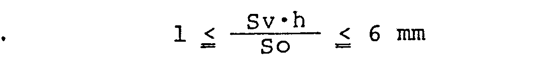
- the shock absorber is provided with a piston having a vortex valve, in which the piston is designed according to the relationship represented by: 1 mm ⁇ ⁇ 6 mm
- the shock absorber comprises a cylindrical tube 2 and a piston 3 movably disposed within the cylinder tube 2 along the longitudinal axis of the cylinder tube.
- the piston 3 is secured on the lower end of a piston rod 4 which has an upper end extending from the tube 2 and attached to a vehicle body chassis (not shown).
- the lower end of the tube 2 is attached to a wheel axle (not shown).
- a free piston 5 with an annular sealing ring 8 is also disposed within the tube 2 to difine therein a pneumatic chamber 6.
- a chamber 7 difined above the free piston 5 is filled with a working fluid.
- the chamber 7 is divided into the upper and lower chamber 7a and 7b by the piston 3.
- the piston 3 is formed with a pair of vortex chambers 9 and 10 respectively of circular in transverse section. Also, the piston 3 is formed with a recesses 13 on the outer circumference.
- the upper vortex chamber 9 communicates with the recess 13 via fluid passages 11, each of which has an outer end opening into the recesses 13 and an inner end opening into the upper vortex chamber 9 in the direction substantially along the normal of the circle of the upper vortex chamber 9.
- the lower vortex chamber 10 communicates with the recesses 13 via fluid passages 12.
- Each of the fluid passage has an outer end opening into the recesses 13 and an inner end opening to the lower vortex in the direction perpendicular to the longitudinal axis of the lower vortex chamber.
- the upper and lower vortex chambers 9 and 10 communicate with one another via the fluid passage 11, the recess 13 and the fluid passage 12.
- the upper vortex chamber 9 also communicates with the upper chamber 7a via fluid passages 14 radially extending from a threaded opening 20 for engagement with the threaded end 22 of the piston rod, and an opening 24 for communication between the threaded opening 20 and the upper vortex chamber 9.
- the lower vortex chamber 1 0 communicates with the lower chamber 7b via an opening 15 formed in the bottom of the lower vortex chamber.
- a suspension spring of a vehicle suspension mechanism In operation, if the vehicle is subject to road shock, a suspension spring of a vehicle suspension mechanism is displaced to absorb the shock. The vehicle will move up and down due to displacement of the suspension spring until the spring returns to the normal state. At this time, the shock absorber works to reduce the vehicle vibration by absorbing the shock.
- the piston 3 In the compression stroke of the piston 3, the piston 3 travels downwardly to expand the volume of the upper chamber 7a and, in turn, reduce the volume of the lower chamber 7b.
- the fluid pressure in the upper chamber 7a is reduced and the fluid pressure in the lower chamber 7b is increased to create a pressure difference between the upper and lower chambers 7a and 7b.
- the fluid in the lower chamber 7b flows into the upper chamber 7a via the piston 3.
- the fluid in the chamber 7b enters the lower vortex chamber 10 through the opening 15.
- the fluid flows via the lower vortex chamber 10, the fluid passages 12, the recess 13 and the fluid passage 11 into the upper vortex chamber 9.
- the fluid is discharged into the upper chamber 7a in the direction substantially along the normal of the circle of the upper vortex chamber in order to produce a vortex therein. Thereafter, the fluid flows into the upper chamber 7a via .the opening 24 and the passages 14.
- the fluid passages 11 and 12 serve as orifices to limit the flow amount of the fluid. In the compression stroke, therefore, the shock absorber 1 absorbs the shock applied to the vehicle by the vortex-and-orifice effect, both serving to limit the fluid flow.
- the volume of the upper chamber 7a is reduced and the volume of the lower chamber 7b is increased to induce fluid flow via the piston 3.
- the vortex is produced in the lower vortex chamber 10 in order to generate the shock absorbing force.
- the effective area S o(mm 2 ) which serves to vary the relative volume of the upper and lower chambers 7a and 7b, and the horizontal cross-sectional area Sv(mm 2 ) of the upper and lower vortex chambers 9 and 10 can be obtained from the following equations respectively:
- piston 3 are such that the relationship between the effective area So and the horizontal cross-sectional area Sv of the vortex chambers 9 and 10 can be represented by:
- the above-specified dimensional relationship can be applied to any hydraulic shock absorber absorbing the shock by generating the vortex. Therefore, in turn, the specific construction of the shock absorber gives no limitation to the present invention in any way. Furthermore, it should be noted that the present invention is designed in accordance with the dimensional relationship of the areas serving to vary the volume of the chambers 7a and 7b and serving to generate a vortex in the vortex chambers 9 and 10.
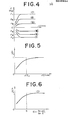
- Fig. 4 shows the relationship between the absorbing force F and the piston stroke ⁇ x.
- lines I, II, III, I', II' and III' respectively represent variation of the absorbing force F with respect to the piston stroke ⁇ x at different motion speeds of the piston 3.
- the lines I, II and III respectively represent variation of the absorbing force F in the expansion stroke of the piston 3 and in respectively different motion speeds I>II>III.
- the lines I', II' and III' respectively represent variation of the absorbing force F in the compression stroke and in respectively different motion speeds I'>II'>III.
- the absorbing force F is proportional to the piston stroke ⁇ x. However, if the piston stroke ⁇ x exceeds a given value, the absorbing force . F becomes substantially constant. In this range, the absorption of the shock effected by the vortex in the vortex chambers 9 and 10 is at its maximum value.
- the maximum absorbing force F is varied depending on the speed of the piston, as represented by F I , F II , F III , F I' , F II', and F III'.
- F/Fo represents relative ratio of the absorbing force to the maximum absorbing force F I , F II , F III , F I' , F II' , and F III' .
- the piston stroke ⁇ xa denoted in Fig. 5 represents the point where the ratio F/Fo becomes approximately 1, which stroke Axa can determined by experiment.
- the piston stroke ⁇ x is equal to or smaller than Axa, the vortex is not induced or insufficiently induce to limit the fluid flow in the vortex chambers 9 and 10. Therefore, the relative ratio is increased mainly depending on the piston stroke ⁇ x.
- Fig. 5 shows the relationship between the relative ratio of the absorbing force F/Fo and the piston stroke ⁇ x in specific construction of the piston as illustrated as above, the relationship shown in Fig. 5 can be varied according to the dimensional relationship of the effective area So, the cross-sectional area Sv of the vortex chamber 9 and 10, and the depth h of the vortex chamber.
- the absorbing force is determined by the amount of the working fluid flowing through one of the vortex chambers 9 or 10 in which a vortex is generated.
- the absorbing force depends on the flow amount of the fluid flowing through an unit volume in the vortex chamber, this fluix being hereafter referred as "flow rate a".
- the fluid flow rate a can be obtained by the following equation:
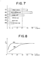
- FIG. 7 there is illustrated a histogram showing characteristic piston stroke ⁇ x corresponding to various vehicle driving conditions.
- the line I represents a characteristic piston stroke ⁇ x when the vehicle turns abruptly. In this driving condition, the piston stroke ⁇ x is approximately 40 mm.
- the line II represents the piston stroke ⁇ x, being approximate 50 mm, in response to rapid acceleration of the vehicle.
- the line III represents the piston stroke ⁇ x, being approximate 35 mm, due to a lane change.
- the line IV represents the piston stroke ⁇ x, about 3 mm, when. the vehicle is driven over a slight bump in the road.
- the line V represents the piston stroke ⁇ x, about 2 mm, on a substantially smooth road.
- the line VI represents the piston stroke ⁇ x, about 14 mm, on a substantially rough road.
- Fig. 8 shows a graph showing the relationship between the relative ratio F/Fo of the absorbing force and the piston stroke ⁇ x in the cases of the piston design being such that h ⁇ Sv/So equals 1 mm (line VII) or 6 mm (line VIII).
- h ⁇ Sv/So 1 mm
- line VII 6 mm
- Fig. 8 shows a graph showing the relationship between the relative ratio F/Fo of the absorbing force and the piston stroke ⁇ x in the cases of the piston design being such that h ⁇ Sv/So equals 1 mm (line VII) or 6 mm (line VIII).
Abstract
Description
- The present invention relates generally to a hydraulic shock absorber for an automotive vehicle suspension. More specifically, the invention relates to a shock absorber having a vortex chamber in a piston, in which the dimensions of the piston are such that it maximizes the absorbing force created by the vortex therein in response to the substantially unstable vehicle driving conditions and minimize the absorbing force in stable driving conditions.
- Conventionally, it has been well known the shock absorber having a vortex valve in the piston thereof. Generally, in a shock absorber with a vortex valve, the vortex in the vortex chamber in the piston is generated corresponding to the flow amount of the working fluid. The vortex generated in the vortex chamber limit the fluid flow between the upper and lower fluid chambers defined in the absorber housing and separated by the piston.
- Since such a vortex valve shock absorber produces the absorbing force against the shock mainly depending on the piston stroke and not depending substantially on the motion speed of the piston, the absorbing force can be reduced in a range where the piston stroke is relatively small and therefore a significant absorbing force is not required. This ensures a comfortable ride.
- However, in spite of the above-mentioned- advantages expectable of such a vortex valve shock absorber, it has not been achieved to provide the shock absorber capable of sufficiently varying the absorbing force substantially corresponding to the requirement according to the vehicle driving condition.
- Therefore, it is an object of the present invention to provide a shock absorber with a vortex valve in a piston, wherein the piston and the vortex chamber therein are related dimensionally such that the absorbing force created by the vortex in the vortex chamber can be maximized when the vehicle driving conditions are relatively unstable and minimized in stable driving conditions.
- To accomplish the above-mentioned and other objects of the invention, the shock absorber is provided with a piston having a vortex valve, in which the piston is designed according to the relationship represented by:
1 mm ≦
- where So: cross-sectional area of the piston varying the relative volume of fluid chambers defined in the shock absorber to vary the relative pressure of the working fluid in the fluid chambers;
- Sv: cross-sectional area of the vortex chamber; and
- h: depth or the vortex chamber
- The present invention will become more fully understood from the detailed description given herebelow and from the accompanying drawings of a preferred embodiment of the present invention, which, however, should not be taken as limitative of the invention but for elucidation and explanation only.
- In the drawings:
- Fig. 1 is a longitudinal section of a preferred embodiment of a shock absorber according to the present invention;
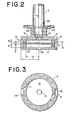
- Fig. 2 is an enlarged section of a piston used in the shock absorber of Fig. 1;
- Fig. 3 is an enlarged transverse section of the piston taken along line A-A of Fig. 2;
- Fig. 4 is a graph showing the relationship between the absorbing force F and the piston stroke Δx, wherein the area above the horizontal axis shows variation of the absorbing force corresponding to the compression stroke of the piston and the area below the horizontal axis shows the relation between the absorbing force and the piston stroke in the expansion stroke, and wherein FI, FII, FIII, FI', FII', and FIII respectively show variation of the absorbing force with respect to the piston stroke at various piston speeds;
- Fig. 5 is a graph showing variation of ratio F/Fo of the absorbing force to the maximum absorbing force with respect to the piston stroke Δx;
- Fig. 6 is a graph showing variation of ratio F/Fo of the absorbing force to the maximum absorbing force with respect to an amount of the working fluid a flowing in the piston vortex chamber;
- Fig. 7 illustrates required absorbing forces in various driving conditions; (I) abrupt turning, (II) rapid acceleration, (III) lane change, (IV) crossing a bump, (V) on a smooth road, and (VI) on a rough road; and
- Fig. 8 is a graph showing variation of the ratio F/Fo of the absorbing force to the maximum absorbing force with respect to the piston stroke Δx.
- Referring now to the drawings, particularly to Figs. 1, 2 and 3, there is illustrated a preferred embodiment of a shock absorber 1 in accordance with the present invention. The shock absorber comprises a
cylindrical tube 2 and apiston 3 movably disposed within thecylinder tube 2 along the longitudinal axis of the cylinder tube. Thepiston 3 is secured on the lower end of apiston rod 4 which has an upper end extending from thetube 2 and attached to a vehicle body chassis (not shown). On the other hand, the lower end of thetube 2 is attached to a wheel axle (not shown). Afree piston 5 with an annular sealing ring 8 is also disposed within thetube 2 to difine therein apneumatic chamber 6. A chamber 7 difined above thefree piston 5 is filled with a working fluid. The chamber 7 is divided into the upper andlower chamber 7a and 7b by thepiston 3. - As shown in Figs. 2 and 3, the
piston 3 is formed with a pair ofvortex chambers piston 3 is formed with arecesses 13 on the outer circumference. Theupper vortex chamber 9 communicates with therecess 13 viafluid passages 11, each of which has an outer end opening into therecesses 13 and an inner end opening into theupper vortex chamber 9 in the direction substantially along the normal of the circle of theupper vortex chamber 9. Likewise, thelower vortex chamber 10 communicates with therecesses 13 viafluid passages 12. Each of the fluid passage has an outer end opening into therecesses 13 and an inner end opening to the lower vortex in the direction perpendicular to the longitudinal axis of the lower vortex chamber. Thus, the upper andlower vortex chambers fluid passage 11, therecess 13 and thefluid passage 12. - The
upper vortex chamber 9 also communicates with theupper chamber 7a viafluid passages 14 radially extending from a threadedopening 20 for engagement with the threadedend 22 of the piston rod, and anopening 24 for communication between the threadedopening 20 and theupper vortex chamber 9. On the other hand, thelower vortex chamber 10 communicates with the lower chamber 7b via anopening 15 formed in the bottom of the lower vortex chamber. - In operation, if the vehicle is subject to road shock, a suspension spring of a vehicle suspension mechanism is displaced to absorb the shock. The vehicle will move up and down due to displacement of the suspension spring until the spring returns to the normal state. At this time, the shock absorber works to reduce the vehicle vibration by absorbing the shock.
- In the compression stroke of the
piston 3, thepiston 3 travels downwardly to expand the volume of theupper chamber 7a and, in turn, reduce the volume of the lower chamber 7b. Corresponding to the piston stroke, the fluid pressure in theupper chamber 7a is reduced and the fluid pressure in the lower chamber 7b is increased to create a pressure difference between the upper andlower chambers 7a and 7b. As a result, the fluid in the lower chamber 7b flows into theupper chamber 7a via thepiston 3. The fluid in the chamber 7b enters thelower vortex chamber 10 through theopening 15. The fluid flows via thelower vortex chamber 10, thefluid passages 12, therecess 13 and thefluid passage 11 into theupper vortex chamber 9. From thefluid passage 11, the fluid is discharged into theupper chamber 7a in the direction substantially along the normal of the circle of the upper vortex chamber in order to produce a vortex therein. Thereafter, the fluid flows into theupper chamber 7a via .the opening 24 and thepassages 14. At the same time, thefluid passages - Likewise, in the expansion stroke of the
piston 3, the volume of theupper chamber 7a is reduced and the volume of the lower chamber 7b is increased to induce fluid flow via thepiston 3. During the fluid flow through thevortex chambers lower vortex chamber 10 in order to generate the shock absorbing force. - Here, with respect to the dimensional relationship of the piston, the effective area So(mm2), which serves to vary the relative volume of the upper and
lower chambers 7a and 7b, and the horizontal cross-sectional area Sv(mm2) of the upper andlower vortex chambers 

- In the preferred embodiment, the dimensions of
piston 3 are such that the relationship between the effective area So and the horizontal cross-sectional area Sv of thevortex chambers 
- . It should be noted that the above-specified dimensional relationship can be applied to any hydraulic shock absorber absorbing the shock by generating the vortex. Therefore, in turn, the specific construction of the shock absorber gives no limitation to the present invention in any way. Furthermore, it should be noted that the present invention is designed in accordance with the dimensional relationship of the areas serving to vary the volume of the
chambers 7a and 7b and serving to generate a vortex in thevortex chambers - Now, we refer to Figs. 4 to 8 and explain in greater detail the present invention with reference to those figures. Fig. 4 shows the relationship between the absorbing force F and the piston stroke Δx. In Fig. 4, lines I, II, III, I', II' and III' respectively represent variation of the absorbing force F with respect to the piston stroke Δx at different motion speeds of the
piston 3. The lines I, II and III respectively represent variation of the absorbing force F in the expansion stroke of thepiston 3 and in respectively different motion speeds I>II>III. On the other hand, the lines I', II' and III' respectively represent variation of the absorbing force F in the compression stroke and in respectively different motion speeds I'>II'>III. - As seen from Fig. 4, the absorbing force F is proportional to the piston stroke Δx. However, if the piston stroke Δx exceeds a given value, the absorbing force . F becomes substantially constant. In this range, the absorption of the shock effected by the vortex in the
vortex chambers - The relationship between the absorbing force F and the piston stroke with avoiding the influence of the piston motion speed can be illustrated as shown in Fig. 5. In Fig. 5, F/Fo represents relative ratio of the absorbing force to the maximum absorbing force F I, FII, FIII, FI', FII', and FIII'. The piston stroke Δxa denoted in Fig. 5 represents the point where the ratio F/Fo becomes approximately 1, which stroke Axa can determined by experiment. Within the range where the piston stroke Δx is equal to or smaller than Axa, the vortex is not induced or insufficiently induce to limit the fluid flow in the
vortex chambers - Alternatively, however Fig. 5 shows the relationship between the relative ratio of the absorbing force F/Fo and the piston stroke Δx in specific construction of the piston as illustrated as above, the relationship shown in Fig. 5 can be varied according to the dimensional relationship of the effective area So, the cross-sectional area Sv of the
vortex chamber - Here, the absorbing force is determined by the amount of the working fluid flowing through one of the
vortex chambers 
- Fig. 6 shows the relationship between the ratio F/Fo of the absorbing force and the fluid flow rate α(=So·Δx/Sv·h). As seen in Fig. 6, in the range where the fluid flow rate a is smaller than a given value, for example, 5, the absorbing force varies directly with the piston stroke Δx.
- It should be understood the given value of the fluid flow rate a varies according to the construction of the piston and, therefore, the numerical specification in Fig. 6 merely shows one example of the given value of the fluid flow rate.
- Referring to Fig. 7, there is illustrated a histogram showing characteristic piston stroke Δx corresponding to various vehicle driving conditions. In Fig. 7, the line I represents a characteristic piston stroke Δx when the vehicle turns abruptly. In this driving condition, the piston stroke Δx is approximately 40 mm. Similarly, the line II represents the piston stroke Δx, being approximate 50 mm, in response to rapid acceleration of the vehicle. The line III represents the piston stroke Δx, being approximate 35 mm, due to a lane change. The line IV represents the piston stroke Δx, about 3 mm, when. the vehicle is driven over a slight bump in the road. The line V represents the piston stroke Δx, about 2 mm, on a substantially smooth road. The line VI represents the piston stroke Δx, about 14 mm, on a substantially rough road.
- As understood from Fig. 7, when the vehicle is turned abruptly, rapidly accelerated, or changes lanes, a significant absorbing force is required for adequate driving stability. On the other hand, when the vehicle is driven over a slight bump, on a smooth road, or on a relatively rough road, a significant absorbing force is not required since the vehicle is easily maintained in a stable condition. In the latter driving condition, it is important to provide minimal absorbing force for riding comfort. As understood herefrom, if the piston size is such that given piston stroke Axa can be set in the
range 5 mm≦Δxa≦30 mm, it can be expected that both driving stability and riding comfort can be achieved. - Fig. 8 shows a graph showing the relationship between the relative ratio F/Fo of the absorbing force and the piston stroke Δx in the cases of the piston design being such that h·Sv/So equals 1 mm (line VII) or 6 mm (line VIII). As seen from Fig. 8, if the piston is .designed so as to make h.Sv/So=1 mm, the given piston stroke Axa becomes about 5 mm and on the other hand, if the piston is designed so as to make h.Sv/So=6 mm, the given piston stroke Δxa becomes about 30 mm. Therefore, for achieving both driving stability and riding comfort, it is necessary to design the piston to comform to the relationship between the effective area So, the vortex chamber cross-sectional area Sv, and the vortex chamber depth h as follows:
- Thus, the present invention fulfills all of the objects and advantages sought thereof.
Claims (7)
wherein the vortex chamber being so sized as

Priority Applications (1)
| Application Number | Priority Date | Filing Date | Title |
|---|---|---|---|
| DE8585103408T DE3176931D1 (en) | 1980-08-07 | 1981-08-06 | Shock absorber |
Applications Claiming Priority (2)
| Application Number | Priority Date | Filing Date | Title |
|---|---|---|---|
| JP10896580A JPS5733240A (en) | 1980-08-07 | 1980-08-07 | Shock absorber |
| JP108965/80 | 1980-08-07 |
Related Child Applications (3)
| Application Number | Title | Priority Date | Filing Date |
|---|---|---|---|
| EP85103408.2 Division-Into | 1981-08-06 | ||
| EP85103408A Division-Into EP0161430B1 (en) | 1980-08-07 | 1981-08-06 | Shock absorber |
| EP85103408A Division EP0161430B1 (en) | 1980-08-07 | 1981-08-06 | Shock absorber |
Publications (3)
| Publication Number | Publication Date |
|---|---|
| EP0045954A2 true EP0045954A2 (en) | 1982-02-17 |
| EP0045954A3 EP0045954A3 (en) | 1983-02-23 |
| EP0045954B1 EP0045954B1 (en) | 1988-11-09 |
Family
ID=14498144
Family Applications (2)
| Application Number | Title | Priority Date | Filing Date |
|---|---|---|---|
| EP85103408A Expired EP0161430B1 (en) | 1980-08-07 | 1981-08-06 | Shock absorber |
| EP81106177A Expired EP0045954B1 (en) | 1980-08-07 | 1981-08-06 | Shock absorber |
Family Applications Before (1)
| Application Number | Title | Priority Date | Filing Date |
|---|---|---|---|
| EP85103408A Expired EP0161430B1 (en) | 1980-08-07 | 1981-08-06 | Shock absorber |
Country Status (4)
| Country | Link |
|---|---|
| US (1) | US4418802A (en) |
| EP (2) | EP0161430B1 (en) |
| JP (1) | JPS5733240A (en) |
| DE (1) | DE3176930D1 (en) |
Cited By (2)
| Publication number | Priority date | Publication date | Assignee | Title |
|---|---|---|---|---|
| EP0045973A2 (en) * | 1980-08-13 | 1982-02-17 | Nissan Motor Co., Ltd. | Shock absorber |
| US4515252A (en) * | 1982-05-31 | 1985-05-07 | Nissan Motor Company, Limited | Piston stroke responsive vortex-flow shock absorber |
Families Citing this family (9)
| Publication number | Priority date | Publication date | Assignee | Title |
|---|---|---|---|---|
| FR2513340A1 (en) * | 1981-09-23 | 1983-03-25 | Peugeot | VALVE PISTON FOR SHOCK ABSORBER |
| JPH0645400B2 (en) * | 1984-03-09 | 1994-06-15 | 株式会社タツノ・メカトロニクス | Refueling device |
| JPH085519B2 (en) * | 1987-07-21 | 1996-01-24 | 株式会社タツノ・メカトロニクス | Oil leak detector |
| US5070972A (en) * | 1990-06-18 | 1991-12-10 | General Motors Corporation | Vortex valving assembly for a hydraulic damper |
| IT1266168B1 (en) * | 1994-07-15 | 1996-12-23 | Manuli Rubber Ind Srl | DOUBLE CASE FLEXIBLE HOSE |
| DE102005061164B4 (en) * | 2005-12-21 | 2007-09-13 | Zf Friedrichshafen Ag | Vibration damper with a stop spring |
| JP6245646B2 (en) * | 2014-04-08 | 2017-12-13 | 株式会社ブリヂストン | Vibration isolator |
| RU168465U1 (en) * | 2016-09-14 | 2017-02-06 | Общество с ограниченной ответственностью "Первоуральский Автоагрегатный завод" | HYDRAULIC SHOCK ABSORBER |
| RU204114U1 (en) * | 2020-12-28 | 2021-05-07 | Федеральное государственное бюджетное образовательное учреждение высшего образования "Санкт-Петербургский государственный архитектурно-строительный университет" | Pneumohydraulic shock absorber |
Citations (10)
| Publication number | Priority date | Publication date | Assignee | Title |
|---|---|---|---|---|
| FR845638A (en) * | 1937-11-10 | 1939-08-29 | Kronprinz Ag Fu R Metallindust | Suspension device applicable, for example, to aircraft landing gear |
| DE697799C (en) * | 1937-05-27 | 1940-10-23 | Ver Deutsche Metallwerke Ag | Liquid shock absorbers |
| FR892773A (en) * | 1941-01-23 | 1944-05-19 | Device preventing oil shocks in air shock absorbers with piston moving in a cylinder | |
| GB600386A (en) * | 1944-10-13 | 1948-04-07 | Olaer Marine Soc | Improvements in apparatus including a hydraulic circuit provided with a device for creating a resistance therein |
| US3133615A (en) * | 1962-07-02 | 1964-05-19 | Bendix Corp | Hydraulic shock absorber with improved piston valve means |
| US3220517A (en) * | 1962-10-30 | 1965-11-30 | Best available copy | |
| US3672474A (en) * | 1970-02-16 | 1972-06-27 | Bendix Corp | Fluid flow device for a shock absorber |
| US4082169A (en) * | 1975-12-12 | 1978-04-04 | Bowles Romald E | Acceleration controlled fluidic shock absorber |
| GB2044882A (en) * | 1979-02-27 | 1980-10-22 | Nissan Motor | Hydraulic shock absorber with vortex valve |
| GB2065268A (en) * | 1979-12-18 | 1981-06-24 | Stabilus Gmbh | Fluid spring with meandering passage |
Family Cites Families (2)
| Publication number | Priority date | Publication date | Assignee | Title |
|---|---|---|---|---|
| DE1505478A1 (en) * | 1965-10-29 | 1969-09-25 | Bilstein August Fa | Infinitely adjustable shock absorber, especially for motor vehicles |
| DE2905928A1 (en) * | 1979-02-16 | 1980-08-28 | Fichtel & Sachs Ag | HYDROPNEUMATIC TWO-TUBE VIBRATION DAMPER WITH BLEEDING VALVE |
-
1980
- 1980-08-07 JP JP10896580A patent/JPS5733240A/en active Pending
-
1981
- 1981-07-20 US US06/285,049 patent/US4418802A/en not_active Expired - Fee Related
- 1981-08-06 EP EP85103408A patent/EP0161430B1/en not_active Expired
- 1981-08-06 EP EP81106177A patent/EP0045954B1/en not_active Expired
- 1981-08-06 DE DE8181106177T patent/DE3176930D1/en not_active Expired
Patent Citations (11)
| Publication number | Priority date | Publication date | Assignee | Title |
|---|---|---|---|---|
| DE697799C (en) * | 1937-05-27 | 1940-10-23 | Ver Deutsche Metallwerke Ag | Liquid shock absorbers |
| FR845638A (en) * | 1937-11-10 | 1939-08-29 | Kronprinz Ag Fu R Metallindust | Suspension device applicable, for example, to aircraft landing gear |
| FR892773A (en) * | 1941-01-23 | 1944-05-19 | Device preventing oil shocks in air shock absorbers with piston moving in a cylinder | |
| GB600386A (en) * | 1944-10-13 | 1948-04-07 | Olaer Marine Soc | Improvements in apparatus including a hydraulic circuit provided with a device for creating a resistance therein |
| US3133615A (en) * | 1962-07-02 | 1964-05-19 | Bendix Corp | Hydraulic shock absorber with improved piston valve means |
| US3220517A (en) * | 1962-10-30 | 1965-11-30 | Best available copy | |
| GB1067196A (en) * | 1962-10-30 | 1967-05-03 | R I V Anstalt Zur Verwaltung V | Fluid flow regulator |
| US3672474A (en) * | 1970-02-16 | 1972-06-27 | Bendix Corp | Fluid flow device for a shock absorber |
| US4082169A (en) * | 1975-12-12 | 1978-04-04 | Bowles Romald E | Acceleration controlled fluidic shock absorber |
| GB2044882A (en) * | 1979-02-27 | 1980-10-22 | Nissan Motor | Hydraulic shock absorber with vortex valve |
| GB2065268A (en) * | 1979-12-18 | 1981-06-24 | Stabilus Gmbh | Fluid spring with meandering passage |
Cited By (4)
| Publication number | Priority date | Publication date | Assignee | Title |
|---|---|---|---|---|
| EP0045973A2 (en) * | 1980-08-13 | 1982-02-17 | Nissan Motor Co., Ltd. | Shock absorber |
| US4502575A (en) * | 1980-08-13 | 1985-03-05 | Nissan Motor Company, Limited | Shock absorber |
| EP0045973A3 (en) * | 1980-08-14 | 1983-01-12 | Nissan Motor Company, Limited | Shock absorber |
| US4515252A (en) * | 1982-05-31 | 1985-05-07 | Nissan Motor Company, Limited | Piston stroke responsive vortex-flow shock absorber |
Also Published As
| Publication number | Publication date |
|---|---|
| EP0045954A3 (en) | 1983-02-23 |
| EP0045954B1 (en) | 1988-11-09 |
| US4418802A (en) | 1983-12-06 |
| DE3176930D1 (en) | 1988-12-15 |
| JPS5733240A (en) | 1982-02-23 |
| EP0161430A3 (en) | 1986-06-25 |
| EP0161430B1 (en) | 1988-11-09 |
| EP0161430A2 (en) | 1985-11-21 |
Similar Documents
| Publication | Publication Date | Title |
|---|---|---|
| EP0336692B1 (en) | Shock absorber | |
| US5992585A (en) | Acceleration sensitive damping for automotive dampers | |
| EP1158202B1 (en) | Independently tunable variable bleed orifice | |
| KR860001691B1 (en) | Hydraulic damper | |
| EP0045954A2 (en) | Shock absorber | |
| GB2266573A (en) | Variable damping force shock absorber | |
| US6332622B1 (en) | Suspension apparatus having two interconnected shock absorbers | |
| US4262779A (en) | Shock absorber with reservoir and working chamber communicating structure | |
| EP0122532B1 (en) | Shock absorber | |
| US6491313B1 (en) | Variable damper assembly | |
| US4515252A (en) | Piston stroke responsive vortex-flow shock absorber | |
| US4901828A (en) | Method and apparatus for controlling displacement of a piston in a shock absorber | |
| JPH0719643U (en) | Vehicle shock absorber | |
| US4475635A (en) | Vortex flow shock absorber with one-way valve | |
| JPS597057B2 (en) | Vehicle hydraulic shock absorber | |
| JPS5865340A (en) | Oil hydraulic shock absorber | |
| GB2118686A (en) | Hydraulic damper | |
| EP0047954B1 (en) | Vortex flow hydraulic shock absorber | |
| JP4050076B2 (en) | Motorcycle front fork | |
| JPS5926817B2 (en) | Vehicle shock absorber | |
| JPS649502B2 (en) | ||
| EP0060098A2 (en) | Improvements relating to hydropneumatic suspension units | |
| EP0744307B1 (en) | An improved double-acting shock absorber | |
| JPH039445Y2 (en) | ||
| JPS60176808A (en) | Shock absorber |
Legal Events
| Date | Code | Title | Description |
|---|---|---|---|
| PUAI | Public reference made under article 153(3) epc to a published international application that has entered the european phase |
Free format text: ORIGINAL CODE: 0009012 |
|
| AK | Designated contracting states |
Designated state(s): DE FR GB |
|
| PUAL | Search report despatched |
Free format text: ORIGINAL CODE: 0009013 |
|
| AK | Designated contracting states |
Designated state(s): DE FR GB |
|
| 17P | Request for examination filed |
Effective date: 19830114 |
|
| RAP1 | Party data changed (applicant data changed or rights of an application transferred) |
Owner name: NISSAN MOTOR CO., LTD. |
|
| GRAA | (expected) grant |
Free format text: ORIGINAL CODE: 0009210 |
|
| AK | Designated contracting states |
Kind code of ref document: B1 Designated state(s): DE FR GB |
|
| REF | Corresponds to: |
Ref document number: 3176930 Country of ref document: DE Date of ref document: 19881215 |
|
| ET | Fr: translation filed | ||
| PGFP | Annual fee paid to national office [announced via postgrant information from national office to epo] |
Ref country code: FR Payment date: 19890713 Year of fee payment: 9 |
|
| PGFP | Annual fee paid to national office [announced via postgrant information from national office to epo] |
Ref country code: GB Payment date: 19890731 Year of fee payment: 9 |
|
| PGFP | Annual fee paid to national office [announced via postgrant information from national office to epo] |
Ref country code: DE Payment date: 19890831 Year of fee payment: 9 |
|
| PLBE | No opposition filed within time limit |
Free format text: ORIGINAL CODE: 0009261 |
|
| STAA | Information on the status of an ep patent application or granted ep patent |
Free format text: STATUS: NO OPPOSITION FILED WITHIN TIME LIMIT |
|
| 26N | No opposition filed | ||
| PG25 | Lapsed in a contracting state [announced via postgrant information from national office to epo] |
Ref country code: GB Effective date: 19900806 |
|
| GBPC | Gb: european patent ceased through non-payment of renewal fee | ||
| PG25 | Lapsed in a contracting state [announced via postgrant information from national office to epo] |
Ref country code: FR Effective date: 19910430 |
|
| PG25 | Lapsed in a contracting state [announced via postgrant information from national office to epo] |
Ref country code: DE Effective date: 19910501 |
|
| REG | Reference to a national code |
Ref country code: FR Ref legal event code: ST |
|
| APAH | Appeal reference modified |
Free format text: ORIGINAL CODE: EPIDOSCREFNO |