JP6709099B2 - Shock absorber - Google Patents
Shock absorber Download PDFInfo
- Publication number
- JP6709099B2 JP6709099B2 JP2016076256A JP2016076256A JP6709099B2 JP 6709099 B2 JP6709099 B2 JP 6709099B2 JP 2016076256 A JP2016076256 A JP 2016076256A JP 2016076256 A JP2016076256 A JP 2016076256A JP 6709099 B2 JP6709099 B2 JP 6709099B2
- Authority
- JP
- Japan
- Prior art keywords
- chamber
- cylinder
- shock absorber
- elastic member
- piston
- Prior art date
- Legal status (The legal status is an assumption and is not a legal conclusion. Google has not performed a legal analysis and makes no representation as to the accuracy of the status listed.)
- Active
Links
Images


Classifications
-
- F—MECHANICAL ENGINEERING; LIGHTING; HEATING; WEAPONS; BLASTING
- F16—ENGINEERING ELEMENTS AND UNITS; GENERAL MEASURES FOR PRODUCING AND MAINTAINING EFFECTIVE FUNCTIONING OF MACHINES OR INSTALLATIONS; THERMAL INSULATION IN GENERAL
- F16F—SPRINGS; SHOCK-ABSORBERS; MEANS FOR DAMPING VIBRATION
- F16F9/00—Springs, vibration-dampers, shock-absorbers, or similarly-constructed movement-dampers using a fluid or the equivalent as damping medium
- F16F9/32—Details
- F16F9/3207—Constructional features
-
- F—MECHANICAL ENGINEERING; LIGHTING; HEATING; WEAPONS; BLASTING
- F16—ENGINEERING ELEMENTS AND UNITS; GENERAL MEASURES FOR PRODUCING AND MAINTAINING EFFECTIVE FUNCTIONING OF MACHINES OR INSTALLATIONS; THERMAL INSULATION IN GENERAL
- F16F—SPRINGS; SHOCK-ABSORBERS; MEANS FOR DAMPING VIBRATION
- F16F9/00—Springs, vibration-dampers, shock-absorbers, or similarly-constructed movement-dampers using a fluid or the equivalent as damping medium
- F16F9/32—Details
- F16F9/50—Special means providing automatic damping adjustment, i.e. self-adjustment of damping by particular sliding movements of a valve element, other than flexions or displacement of valve discs; Special means providing self-adjustment of spring characteristics
- F16F9/512—Means responsive to load action, i.e. static load on the damper or dynamic fluid pressure changes in the damper, e.g. due to changes in velocity
-
- B—PERFORMING OPERATIONS; TRANSPORTING
- B60—VEHICLES IN GENERAL
- B60G—VEHICLE SUSPENSION ARRANGEMENTS
- B60G13/00—Resilient suspensions characterised by arrangement, location or type of vibration dampers
- B60G13/02—Resilient suspensions characterised by arrangement, location or type of vibration dampers having dampers dissipating energy, e.g. frictionally
- B60G13/06—Resilient suspensions characterised by arrangement, location or type of vibration dampers having dampers dissipating energy, e.g. frictionally of fluid type
- B60G13/08—Resilient suspensions characterised by arrangement, location or type of vibration dampers having dampers dissipating energy, e.g. frictionally of fluid type hydraulic
-
- B—PERFORMING OPERATIONS; TRANSPORTING
- B60—VEHICLES IN GENERAL
- B60G—VEHICLE SUSPENSION ARRANGEMENTS
- B60G17/00—Resilient suspensions having means for adjusting the spring or vibration-damper characteristics, for regulating the distance between a supporting surface and a sprung part of vehicle or for locking suspension during use to meet varying vehicular or surface conditions, e.g. due to speed or load
- B60G17/06—Characteristics of dampers, e.g. mechanical dampers
- B60G17/08—Characteristics of fluid dampers
-
- F—MECHANICAL ENGINEERING; LIGHTING; HEATING; WEAPONS; BLASTING
- F16—ENGINEERING ELEMENTS AND UNITS; GENERAL MEASURES FOR PRODUCING AND MAINTAINING EFFECTIVE FUNCTIONING OF MACHINES OR INSTALLATIONS; THERMAL INSULATION IN GENERAL
- F16F—SPRINGS; SHOCK-ABSORBERS; MEANS FOR DAMPING VIBRATION
- F16F9/00—Springs, vibration-dampers, shock-absorbers, or similarly-constructed movement-dampers using a fluid or the equivalent as damping medium
- F16F9/10—Springs, vibration-dampers, shock-absorbers, or similarly-constructed movement-dampers using a fluid or the equivalent as damping medium using liquid only; using a fluid of which the nature is immaterial
- F16F9/14—Devices with one or more members, e.g. pistons, vanes, moving to and fro in chambers and using throttling effect
- F16F9/16—Devices with one or more members, e.g. pistons, vanes, moving to and fro in chambers and using throttling effect involving only straight-line movement of the effective parts
- F16F9/18—Devices with one or more members, e.g. pistons, vanes, moving to and fro in chambers and using throttling effect involving only straight-line movement of the effective parts with a closed cylinder and a piston separating two or more working spaces therein
- F16F9/19—Devices with one or more members, e.g. pistons, vanes, moving to and fro in chambers and using throttling effect involving only straight-line movement of the effective parts with a closed cylinder and a piston separating two or more working spaces therein with a single cylinder and of single-tube type
-
- F—MECHANICAL ENGINEERING; LIGHTING; HEATING; WEAPONS; BLASTING
- F16—ENGINEERING ELEMENTS AND UNITS; GENERAL MEASURES FOR PRODUCING AND MAINTAINING EFFECTIVE FUNCTIONING OF MACHINES OR INSTALLATIONS; THERMAL INSULATION IN GENERAL
- F16F—SPRINGS; SHOCK-ABSORBERS; MEANS FOR DAMPING VIBRATION
- F16F9/00—Springs, vibration-dampers, shock-absorbers, or similarly-constructed movement-dampers using a fluid or the equivalent as damping medium
- F16F9/32—Details
- F16F9/3207—Constructional features
- F16F9/3214—Constructional features of pistons
-
- B—PERFORMING OPERATIONS; TRANSPORTING
- B60—VEHICLES IN GENERAL
- B60G—VEHICLE SUSPENSION ARRANGEMENTS
- B60G2206/00—Indexing codes related to the manufacturing of suspensions: constructional features, the materials used, procedures or tools
- B60G2206/01—Constructional features of suspension elements, e.g. arms, dampers, springs
- B60G2206/40—Constructional features of dampers and/or springs
- B60G2206/41—Dampers
-
- B—PERFORMING OPERATIONS; TRANSPORTING
- B60—VEHICLES IN GENERAL
- B60G—VEHICLE SUSPENSION ARRANGEMENTS
- B60G2500/00—Indexing codes relating to the regulated action or device
- B60G2500/10—Damping action or damper
-
- F—MECHANICAL ENGINEERING; LIGHTING; HEATING; WEAPONS; BLASTING
- F16—ENGINEERING ELEMENTS AND UNITS; GENERAL MEASURES FOR PRODUCING AND MAINTAINING EFFECTIVE FUNCTIONING OF MACHINES OR INSTALLATIONS; THERMAL INSULATION IN GENERAL
- F16F—SPRINGS; SHOCK-ABSORBERS; MEANS FOR DAMPING VIBRATION
- F16F2228/00—Functional characteristics, e.g. variability, frequency-dependence
- F16F2228/04—Frequency effects
-
- F—MECHANICAL ENGINEERING; LIGHTING; HEATING; WEAPONS; BLASTING
- F16—ENGINEERING ELEMENTS AND UNITS; GENERAL MEASURES FOR PRODUCING AND MAINTAINING EFFECTIVE FUNCTIONING OF MACHINES OR INSTALLATIONS; THERMAL INSULATION IN GENERAL
- F16F—SPRINGS; SHOCK-ABSORBERS; MEANS FOR DAMPING VIBRATION
- F16F2228/00—Functional characteristics, e.g. variability, frequency-dependence
- F16F2228/06—Stiffness
- F16F2228/066—Variable stiffness
-
- F—MECHANICAL ENGINEERING; LIGHTING; HEATING; WEAPONS; BLASTING
- F16—ENGINEERING ELEMENTS AND UNITS; GENERAL MEASURES FOR PRODUCING AND MAINTAINING EFFECTIVE FUNCTIONING OF MACHINES OR INSTALLATIONS; THERMAL INSULATION IN GENERAL
- F16F—SPRINGS; SHOCK-ABSORBERS; MEANS FOR DAMPING VIBRATION
- F16F9/00—Springs, vibration-dampers, shock-absorbers, or similarly-constructed movement-dampers using a fluid or the equivalent as damping medium
- F16F9/06—Springs, vibration-dampers, shock-absorbers, or similarly-constructed movement-dampers using a fluid or the equivalent as damping medium using both gas and liquid
- F16F9/061—Mono-tubular units
-
- F—MECHANICAL ENGINEERING; LIGHTING; HEATING; WEAPONS; BLASTING
- F16—ENGINEERING ELEMENTS AND UNITS; GENERAL MEASURES FOR PRODUCING AND MAINTAINING EFFECTIVE FUNCTIONING OF MACHINES OR INSTALLATIONS; THERMAL INSULATION IN GENERAL
- F16F—SPRINGS; SHOCK-ABSORBERS; MEANS FOR DAMPING VIBRATION
- F16F9/00—Springs, vibration-dampers, shock-absorbers, or similarly-constructed movement-dampers using a fluid or the equivalent as damping medium
- F16F9/06—Springs, vibration-dampers, shock-absorbers, or similarly-constructed movement-dampers using a fluid or the equivalent as damping medium using both gas and liquid
- F16F9/064—Units characterised by the location or shape of the expansion chamber
- F16F9/065—Expansion chamber provided on the upper or lower end of a damper, separately there from or laterally on the damper
-
- F—MECHANICAL ENGINEERING; LIGHTING; HEATING; WEAPONS; BLASTING
- F16—ENGINEERING ELEMENTS AND UNITS; GENERAL MEASURES FOR PRODUCING AND MAINTAINING EFFECTIVE FUNCTIONING OF MACHINES OR INSTALLATIONS; THERMAL INSULATION IN GENERAL
- F16F—SPRINGS; SHOCK-ABSORBERS; MEANS FOR DAMPING VIBRATION
- F16F9/00—Springs, vibration-dampers, shock-absorbers, or similarly-constructed movement-dampers using a fluid or the equivalent as damping medium
- F16F9/10—Springs, vibration-dampers, shock-absorbers, or similarly-constructed movement-dampers using a fluid or the equivalent as damping medium using liquid only; using a fluid of which the nature is immaterial
- F16F9/14—Devices with one or more members, e.g. pistons, vanes, moving to and fro in chambers and using throttling effect
- F16F9/16—Devices with one or more members, e.g. pistons, vanes, moving to and fro in chambers and using throttling effect involving only straight-line movement of the effective parts
- F16F9/18—Devices with one or more members, e.g. pistons, vanes, moving to and fro in chambers and using throttling effect involving only straight-line movement of the effective parts with a closed cylinder and a piston separating two or more working spaces therein
- F16F9/182—Devices with one or more members, e.g. pistons, vanes, moving to and fro in chambers and using throttling effect involving only straight-line movement of the effective parts with a closed cylinder and a piston separating two or more working spaces therein comprising a hollow piston rod
-
- F—MECHANICAL ENGINEERING; LIGHTING; HEATING; WEAPONS; BLASTING
- F16—ENGINEERING ELEMENTS AND UNITS; GENERAL MEASURES FOR PRODUCING AND MAINTAINING EFFECTIVE FUNCTIONING OF MACHINES OR INSTALLATIONS; THERMAL INSULATION IN GENERAL
- F16F—SPRINGS; SHOCK-ABSORBERS; MEANS FOR DAMPING VIBRATION
- F16F9/00—Springs, vibration-dampers, shock-absorbers, or similarly-constructed movement-dampers using a fluid or the equivalent as damping medium
- F16F9/32—Details
- F16F9/3207—Constructional features
- F16F9/3228—Constructional features of connections between pistons and piston rods
-
- F—MECHANICAL ENGINEERING; LIGHTING; HEATING; WEAPONS; BLASTING
- F16—ENGINEERING ELEMENTS AND UNITS; GENERAL MEASURES FOR PRODUCING AND MAINTAINING EFFECTIVE FUNCTIONING OF MACHINES OR INSTALLATIONS; THERMAL INSULATION IN GENERAL
- F16F—SPRINGS; SHOCK-ABSORBERS; MEANS FOR DAMPING VIBRATION
- F16F9/00—Springs, vibration-dampers, shock-absorbers, or similarly-constructed movement-dampers using a fluid or the equivalent as damping medium
- F16F9/32—Details
- F16F9/3271—Assembly or repair
Landscapes
- Engineering & Computer Science (AREA)
- General Engineering & Computer Science (AREA)
- Mechanical Engineering (AREA)
- Physics & Mathematics (AREA)
- Fluid Mechanics (AREA)
- Fluid-Damping Devices (AREA)
Description
本発明は、緩衝器に関する。 The present invention relates to a shock absorber.
従来、緩衝器は、車両の車体と車軸との間に介装されて車体振動を抑制する目的で使用される。例えば、特許文献1,2に記載の緩衝器は、シリンダと、シリンダ内に摺動自在に挿入されるピストンと、一端がピストンに連結されて他端がシリンダ外に延びるピストンロッドと、シリンダ内に形成されてピストンで区画される上室及び下室と、上室と下室を連通する第1通路及び第2通路と、第2通路の途中に設けた圧力室と、内部に圧力室が形成されてピストンロッドの先端に取り付けられるハウジングと、ハウジング内に摺動自在に挿入されて、圧力室を下室に連通される一方室と上室に連通される他方室とに区画するフリーピストンと、フリーピストンの圧力室に対する変位を抑制する附勢力を発揮するコイルばねとを備えて構成される。
Conventionally, a shock absorber is interposed between a vehicle body and an axle of a vehicle and is used for the purpose of suppressing vehicle body vibration. For example, the shock absorbers described in
このように構成された緩衝器では、第2通路を介しては上室と下室が直接的に連通されてはいないが、フリーピストンが移動すると圧力室における一方室と他方室の容積比が変化し、フリーピストンの移動量に応じて圧力室内の液体が上室と下室へ出入りするため、見掛け上、上室と下室が第2通路を介して連通されているが如くに振る舞う。 In the shock absorber thus configured, the upper chamber and the lower chamber are not directly communicated with each other via the second passage, but when the free piston moves, the volume ratio of the one chamber and the other chamber in the pressure chamber becomes smaller. The liquid in the pressure chamber changes in accordance with the amount of movement of the free piston and flows in and out of the upper chamber and the lower chamber, so that it behaves as if the upper chamber and the lower chamber are communicated with each other through the second passage.
このため、この緩衝器は、低周波数の振動の入力に対しては高い減衰力を発生し、高周波数の振動の入力に対しては低い減衰力を発生できる。よって、車両が旋回中等の入力振動周波数が低い場面においては、緩衝器が高い減衰力を発生可能であるとともに、車両が路面の凹凸を通過するような入力振動周波数が高い場面においては、緩衝器に低い減衰力を確実に発生させて、車両における乗り心地を向上できる。 Therefore, this shock absorber can generate a high damping force for a low-frequency vibration input and a low damping force for a high-frequency vibration input. Therefore, in a situation where the input vibration frequency is low, such as when the vehicle is turning, the shock absorber can generate a high damping force, and in the scene where the input vibration frequency is high such that the vehicle passes through the unevenness of the road surface, the shock absorber is high. It is possible to reliably generate a low damping force and improve the riding comfort of the vehicle.
しかしながら、上記した従来の緩衝器では、圧力室を区画するフリーピストンをハウジングの内周に摺接させる構造となっている。このような二部材を摺接させる摺動部では、高い加工精度が要求されるので、部品自体が高価になる。 However, the conventional shock absorber described above has a structure in which the free piston that defines the pressure chamber is slidably contacted with the inner circumference of the housing. Since high processing accuracy is required in such a sliding portion that slidably contacts the two members, the component itself becomes expensive.
そこで、本発明は、周波数に応じた減衰力を発揮できるとともに、コストを低減できる緩衝器の提供を目的とする。 Therefore, an object of the present invention is to provide a shock absorber capable of exhibiting a damping force according to frequency and reducing costs.
上記課題を解決するため、本発明は、ピストンで区画される二つの作動室を連通する減衰通路と、前記二つの作動室に連通される圧力室と、前記圧力室を一方の前記作動室に連通される第一室と、他方の前記作動室に連通される第二室とに区画する弾性部材とを備える。当該構成によれば、緩衝器が伸縮作動する際に弾性部材が弾性変形して第一室と第二室の容積比が変化し、弾性変形量に応じて圧力室内の液体が第一室と第二室へ出入りするため、見掛け上、圧力室を介して二つの作動室の間を液体が移動したようになる。加えて、圧力室を区画する隔壁を弾性部材にして摺動させない構造にしているので、高い加工精度が要求されず、部品自体を安価にできる。 In order to solve the above problems , the present invention provides a damping passage that communicates two working chambers defined by a piston, a pressure chamber that communicates with the two working chambers, and the pressure chamber to one of the working chambers. An elastic member is provided that partitions into a first chamber that communicates with a second chamber that communicates with the other working chamber. According to the configuration, when the shock absorber expands and contracts, the elastic member elastically deforms to change the volume ratio of the first chamber and the second chamber, and the liquid in the pressure chamber becomes the first chamber according to the elastic deformation amount. Since the liquid enters and leaves the second chamber, it is apparent that the liquid has moved between the two working chambers via the pressure chamber. In addition, since the partition that divides the pressure chamber is made of an elastic member and is not slidable, high processing accuracy is not required and the cost of the component itself can be reduced.
また、本発明は、前記構成に加えて、内周に前記弾性部材が焼付けにより一体化された状態となっている筒と、内部に前記圧力室が形成されており、前記筒を軸方向の両側から挟み込んでいるハウジングとを備える。よって、弾性部材を筒に強固に接着できるとともに、筒の軸方向の両端部をハウジングに密着させてこれらの間を容易に塞げる。 Further, in addition to the above structure , the present invention has a cylinder in which the elastic member is integrated by baking on the inner periphery, and the pressure chamber is formed inside, and the cylinder is arranged in the axial direction. And a housing sandwiched from both sides. Therefore, the elastic member can be firmly adhered to the cylinder, and both ends of the cylinder in the axial direction are brought into close contact with the housing to easily close the gap between them.
本発明の緩衝器によれば、周波数に応じた減衰力を発揮できるとともに、コストを低減できる。 According to the shock absorber of the present invention, the damping force according to the frequency can be exhibited and the cost can be reduced.
以下に本発明の実施の形態について、図面を参照しながら説明する。いくつかの図面を通して付された同じ符号は、同じ部品か対応する部品を示す。 Embodiments of the present invention will be described below with reference to the drawings. The same reference numerals allotted throughout the several figures refer to the same or corresponding parts.
<第一の実施の形態>
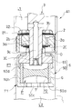
図1に示す本発明の第一の実施の形態に係る緩衝器A1は、車両における車体と車軸との間に介装されて減衰力を発揮し、車体の振動を抑制する。上記緩衝器A1は、シリンダ1と、このシリンダ1内に摺動自在に挿入されるピストン2と、一端がピストン2に連結されて他端がシリンダ1外に延びるピストンロッド3と、ピストンロッド3におけるピストン2の図1中下側に取り付けられる周波数感応部F1と、シリンダ1内における反ピストンロッド側に摺動自在に挿入される摺動隔壁4とを備える。
<First embodiment>
The shock absorber A1 according to the first embodiment of the present invention shown in FIG. 1 is interposed between a vehicle body and an axle of a vehicle to exert a damping force and suppress vibration of the vehicle body. The shock absorber A1 includes a
そして、シリンダ1が取付部材10を介して車体と車軸の一方に連結され、ピストンロッド3が取付部材(図示せず)を介して車体と車軸の他方に連結される。よって、車体と車軸が離間すると、ピストンロッド3がシリンダ1から退出して緩衝器A1が伸長作動し、反対に車体と車軸が接近すると、ピストンロッド3がシリンダ1内に進入して緩衝器A1が収縮作動する。
Then, the
シリンダ1内には、ピストン2で区画される伸側室L1と圧側室L2が形成されるとともに、摺動隔壁4で圧側室L2と区画される気室Gが形成されている。伸側室L1及び圧側室L2は、作動室であり、作動油等の液体で満たされている。また、気室Gには気体が封入されている。シリンダ1は有底筒状に形成されており、シリンダ1の開口端部にはピストンロッド3を軸方向に移動自在に軸支するロッドガイド11が設けられている。そして、シリンダ1とピストンロッド3との間がロッドガイド11に積層されたシール部材12によりシールされる。よって、シリンダ1内の液体及び気体がシリンダ1外に漏れず、シリンダ1内が外気と区画される。
In the
また、上記緩衝器A1では、ピストンロッド3が伸側室L1のみに挿通される片ロッド型となっており、ピストンロッド出没体積分のシリンダ内容積変化を気室Gで補償する。具体的には、ピストンロッド3がシリンダ1から退出する緩衝器A1の伸長作動時には、ピストンロッド退出体積分シリンダ内容積が増加するが、摺動隔壁4が図1中上方へ移動して気室Gが拡大し、シリンダ内容積増加分を補償する。反対に、ピストンロッド3がシリンダ1に進入する緩衝器A1の収縮作動時には、ピストンロッド進入体積分シリンダ内容積が減少するが、摺動隔壁4が図1中下方へ移動して気室Gが縮小し、シリンダ内容積減少分を補償する。
Further, in the above-mentioned shock absorber A1, the
つづいて、ピストン2には、伸側室L1と圧側室L2とを連通する減衰通路として伸側減衰通路2a及び圧側減衰通路2bが設けられている。伸側減衰通路2a及び圧側減衰通路2bの出口には、減衰力発生要素としてリーフバルブ20,21が設けられている。そして、伸側減衰通路2aを通過する液体の流れにリーフバルブ20で抵抗を与え、圧側減衰通路2bを通過する液体の流れにリーフバルブ21で抵抗を与える。詳しくは、リーフバルブ20は、ピストン2の図1中下側に積層されていて、伸側減衰通路2aの出口端を開閉し、伸側減衰通路2aを伸側室L1から圧側室L2へ向かう液体の流れのみを許容して一方通行にする。他方のリーフバルブ21は、ピストン2の図1中上側に積層されていて、圧側減衰通路2bの出口端を開閉し、圧側減衰通路2bを圧側室L2から伸側室L1へ向かう液体の流れのみを許容して一方通行にする。
Subsequently, the
また、リーフバルブ21の図1中上方には、環状のバルブストッパ22が積層されている。ピストン2、リーフバルブ20,21及びバルブストッパ22は、ともに、中心部を貫通する中心孔を有する。そして、ピストン2の一方側にリーフバルブ21及びバルブストッパ22をこの順に重ね、ピストン2の他方側にリーフバルブ20を重ね、これらの中心孔にバルブストッパ22側からピストンロッド3の小径部3a(図2)を挿通し、当該小径部3aの先端に周波数感応部F1の後述するハウジング5を螺合する。すると、ピストン2、リーフバルブ20,21及びバルブストッパ22がその内周部をピストンロッド3の段部3b(図2)とハウジング5との間に挟まれて固定される。このように、ハウジング5は、ピストン2と、当該ピストン2に積層されるバルブ類をピストンロッド3に装着するためのピストンナットとしても機能する。
An
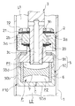
周波数感応部F1は、図2に示すように、上記ハウジング5と、このハウジング5内に収容される筒6と、この筒6の内周に取り付けられる弾性部材7とを有する。ハウジング5は、環状の底部50aと、この底部50aの外周から図2中上方へ起立する筒部50bとを有する有底筒状のケース50と、筒部50bの図2中上端部となる先端部に固定され、ピストンロッド3の外周に螺合する環状の蓋部51とを備えて構成される。また、筒6は、ケース50の筒部50b内に挿入されて、外周を当該筒部50bで支えられる。筒6は、金属製であり、その内周に弾性部材7が焼付けにより取り付けられている。弾性部材7は、ゴム等のエラストマーであり、筒6の軸方向の中央部を隙間なく埋めている。
As shown in FIG. 2, the frequency sensitive portion F1 includes the
そして、ケース50と蓋部51とで囲われるハウジング5の内部であって筒6の内側に圧力室Pが形成され、この圧力室Pが弾性部材7により図2中上側の第一室P1と図2中下側の第二室P2に区画される。第一室P1は、ピストンロッド3の先端から側部にかけて形成される通孔3cにより伸側室L1と連通され、第二室P2は、ケース50の底部50aの中心部を貫通する孔50cにより圧側室L2と連通される。ピストンロッド3の先端部内周には有頂筒状の絞り部材30が嵌合し、当該絞り部材30により通孔3cの一部を絞ってオリフィスOを形成する。
A pressure chamber P is formed inside the
また、ケース50に弾性部材7付きの筒6を挿入してから蓋部51を挿入し、ケース50の筒部50bの先端を内側に加締めると、蓋部51とケース50の底部50aとで筒6が挟まれて固定される。このように筒6が固定されると、筒6の一端が蓋部51に押し付けられ、他端が底部50aに押し付けられるので、筒6の内側の液体が外周側に流出するのを防ぎ、第一室P1と第二室P2が筒6の外周とハウジング5との隙間を介して連通されるのを防止する。
Further, when the
上記筒部50bの肉厚は、当該筒部50bの内周に設けた段部50dを境に先端側が薄く、末端側が厚くなっており、加締め加工が容易である。また、筒部50bにおいて、肉厚が厚い部分の軸方向長さが筒6の軸方向長さよりも短いので、筒部50bの先端を加締めたとき、蓋部51が段部50dに干渉せず、筒6に確実に軸方向に力を加えられる。
The wall thickness of the
さらに、前述のようにケース50における筒部50bの先端を加締めてハウジング5で筒6を挟み込むと、ハウジング5、筒6及び弾性部材7を一体化した状態でピストンロッド3に取り付けられる。ケース50の底部50aに設けた孔50cは、断面六角形状であって、当該孔50cに工具を差し込むと当該工具との相対回転が阻止される。よって、孔50cは、圧側室L2と第二室P2とを連通する流路としての役割を担うとともに、ピストンロッド3にハウジング5を螺合する際に利用される工具の差し込み孔としても利用される。
Further, as described above, when the tip of the
以下、本実施の形態に係る緩衝器A1の作動について説明する。 Hereinafter, the operation of the shock absorber A1 according to the present embodiment will be described.
緩衝器A1の伸長作動時には、シリンダ1に対してピストン2が図1中上方へ移動して伸側室L1を圧縮し、圧側室L2を拡大する。すると、伸側室L1の圧力が高まると同時に圧側室L2の圧力が低下して両者に差圧が生じ、伸側室L1の液体が伸側減衰通路2aを通って圧側室L2へ移動する。また、伸側室L1の圧力が高まると、この圧力が通孔3c及びオリフィスOを介して第一室P1に伝わって弾性部材7を第二室P2側へ撓ませる。すると、第一室P1の容積が拡大するとともに、その分、第二室P2の容積が縮小されて、第二室P2の液体が孔50cを介して圧側室L2へ押し出される。
During the expansion operation of the shock absorber A1, the
反対に、緩衝器A1の収縮作動時には、シリンダ1に対してピストン2が図1中下方へ移動して圧側室L2を圧縮し、伸側室L1を拡大する。すると、圧側室L2の圧力が高まると同時に伸側室L1の圧力が低下して両者に差圧が生じ、圧側室L2の液体が圧側減衰通路2bを通って伸側室L1へ移動する。また、圧側室L2の圧力が高まると、その圧力が孔50cを介して第二室P2に伝わって弾性部材7を第一室P1側へ撓ませる。すると、第二室P2の容積が拡大するとともに、その分、第一室P1の容積が縮小されて、第一室P1の液体が通孔3c及びオリフィスOを介して伸側室L1へ押し出される。
On the contrary, when the shock absorber A1 contracts, the
このように、緩衝器A1の伸縮作動時において液体は、弾性部材7を弾性変形させて第一室P1と第二室P2の一方に流入した分、第一室P1と第二室P2の他方から押し出されるので、伸側減衰通路2a及び圧側減衰通路2bの他にも、見掛け上、圧力室Pを介して伸側室L1と圧側室L2との間を移動したようになる。
In this way, when the shock absorber A1 expands and contracts, the liquid elastically deforms the
ここで、緩衝器A1に入力される振動の周波数、即ち、緩衝器A1の伸縮の振動の周波数が低周波であっても高周波であっても、緩衝器A1の伸縮作動におけるピストン速度が同じである場合、低周波振動入力時の緩衝器A1の振幅は、高周波振動入力時の緩衝器A1の振幅よりも大きくなる。このように緩衝器A1に入力される振動の周波数が低い場合、振幅が大きいため、振動の一周期の間に伸側室L1と圧側室L2との間を移動する液体の量が大きくなって、弾性部材7の変形量が大きくなる。すると、当該変形に抗する弾性部材7の弾性力が大きくなり、その分、第一室P1と第二室P2に差圧が生じて、伸側室L1と第一室P1との差圧、及び圧側室L2と第二室P2との差圧が小さくなり、圧力室Pを介して移動する見掛け上の液体の流量が小さくなる。この見掛け上の流量が小さい分、伸側減衰通路2a及び圧側減衰通路2bを移動する液体の流量が大きくなるので、緩衝器A1が発生する減衰力が高いまま維持される。
Here, even if the frequency of the vibration input to the shock absorber A1, that is, the frequency of the expansion and contraction vibration of the shock absorber A1 is low or high, the piston speed in the expansion and contraction operation of the shock absorber A1 is the same. In some cases, the amplitude of the shock absorber A1 at the time of low frequency vibration input is larger than the amplitude of the shock absorber A1 at the time of high frequency vibration input. When the frequency of the vibration input to the shock absorber A1 is low as described above, the amplitude is large, so that the amount of the liquid that moves between the expansion side chamber L1 and the compression side chamber L2 during one cycle of the vibration becomes large, The amount of deformation of the
また、緩衝器A1に高周波振動が入力される場合、低周波振動入力時よりも振幅が小さいので、振動の一周期の間に伸側室L1と圧側室L2との間を移動する液体の量が小さく、弾性部材7の変形量も小さくなる。すると、当該変形に抗する弾性部材7の弾性力が小さくなり、その分、第一室P1と第二室P2の差圧が小さくなって第一室P1と第二室P2がほぼ同圧になり、伸側室L1と第一室P1との差圧、及び圧側室L2と第二室P2との差圧が低周波振動入力時よりも大きくなって、上記見掛け上の流量が低周波振動入力時よりも増大する。この見掛け上の流量が増大した分、伸側減衰通路2a及び圧側減衰通路2bを移動する液体の流量が減少するので、緩衝器A1が発生する減衰力が低周波振動入力時よりも低くなる。
Further, when high-frequency vibration is input to the shock absorber A1, since the amplitude is smaller than when low-frequency vibration is input, the amount of liquid moving between the extension side chamber L1 and the compression side chamber L2 during one cycle of the vibration is large. The deformation amount of the
以下、本実施の形態に係る緩衝器A1の作用効果について説明する。 Hereinafter, the function and effect of the shock absorber A1 according to the present embodiment will be described.
本実施の形態において、圧側室L2と第二室P2を連通する孔50cは、断面六角形状となっている。よって、当該孔50cを工具の差し込み孔としても利用できるが、孔50cの形状は適宜変更できる。例えば、ハウジング5におけるケース50の底部50aに直径方向に並ぶ一対の孔を形成した場合にも、上記と同様の効果を得られる。
In the present embodiment, the
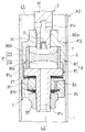
また、本実施の形態において、オリフィスOは、伸側室L1と第一室P1とを連通する通孔3cの途中に設けられている。さらに、オリフィスOはピストンロッド3の内周に嵌合し、通孔3cの途中に設けられる絞り部材30に形成されている。よって、オリフィスOを形成するための加工が容易である。さらに、オリフィスOによる抵抗を変更したい場合には、開口面積の異なるオリフィスOを有する他の絞り部材30に変更すればよくチューニングし易い。しかし、オリフィスOは、伸側室L1と第一室P1とを連通する流路と、圧側室L2と第二室P2とを連通する流路の何れに設けられていてもよい。例えば、図3には、ハウジング5におけるケース50の底部50aに、孔50cに替えてオリフィスOを設けた周波数感応部F10を示している。この場合には、ハウジング5の外周に工具を引っ掛けられるよう、二面幅部を設けるのが好ましい。
Further, in the present embodiment, the orifice O is provided in the middle of the through
また、本実施の形態において、緩衝器A1は、内周に弾性部材7が焼付けにより一体化された筒6と、この筒6を軸方向の両側から挟み込み、内部に圧力室Pが形成されるハウジング5とを備える。当該構成によれば、弾性部材7が筒6に焼付けにより一体化されているので、弾性部材7を筒6に強固に接着できて、弾性部材7が筒6内でずれたり、筒6から外れたりするのを容易且つ確実に防止できる。加えて、弾性部材7と筒6との間に隙間ができるのを防止できる。また、筒6を軸方向の両側からハウジング5で挟み込んでいるので、筒6の軸方向の両端部をハウジング5に密着させて、これらの間を容易に塞げる。つまり、上記構成によれば、弾性部材7で圧力室Pを区画するのを、容易且つ安価に実現できる。
Further, in the present embodiment, the shock absorber A1 has a
なお、弾性部材7の取付方法は焼付けに限られず、適宜変更できる。例えば、弾性部材7を環状のシート状にし、その外周部をリング等で筒6の内周に押し付けるようにしてもよい。このように弾性部材7を取り付ける場合には、筒6を廃し、ケース50の筒部50b内周に直接弾性部材7を取り付けてもよい。また、上記筒部50bの内周に弾性部材7を焼付けにより直接取り付けてもよい。この場合、底部50aと筒部50bが個別に形成された後、嵌合、螺合、溶接等でハウジング5として一体化すると、弾性部材7をハウジング5の内周に焼付けにより容易に取り付けられる。そして、このような変更は、孔50cの形状、及びオリフィスOの位置によらず可能である。
The method of attaching the
また、本実施の形態において、緩衝器A1は、シリンダ1と、このシリンダ1内に移動自在に挿入されてシリンダ1内を伸側室(一方の作動室)L1と圧側室(他方の作動室)L2に区画するピストン2と、伸側室L1と圧側室L2を連通する伸側減衰通路2a(減衰通路)及び圧側減衰通路2b(減衰通路)と、伸側室L1と圧側室L2に連通される圧力室Pと、この圧力室Pを伸側室L1に連通される第一室P1と、圧側室L2に連通される第二室P2とに区画する弾性部材7とを備える。
In addition, in the present embodiment, the shock absorber A1 is a
上記構成によれば、緩衝器A1が伸縮作動する際に弾性部材7が弾性変形して第一室P1と第二室P2の容積比が変化し、弾性変形量に応じて圧力室P内の液体が第一室P1と第二室P2へ出入りするため、見掛け上、圧力室Pを介して伸側室L1と圧側室L2の間を液体が移動したようになる。この見掛け上の流量は上記弾性変形量に応じて変化し、この流量変化に応じて伸側減衰通路2a及び圧側減衰通路2bの流量が変わるので、入力される振動の周波数に感応して高周波振動入力時に減衰力を低減させる効果を得られる。よって、緩衝器A1は、車両が旋回中等の入力振動周波数が低い場面においては高い減衰力を発揮し、車両が路面の凹凸を通過するような入力振動周波数が高い場面においては低い減衰力を発揮して、車両における乗り心地を向上できる。また、弾性部材7のばね定数は、素材又は厚みの変更等により調整できる。
According to the above configuration, when the shock absorber A1 expands and contracts, the
ここで、従来の周波数に応じた減衰力を発揮する緩衝器では、圧力室をハウジングの内周に摺接するフリーピストンで区画し、当該フリーピストンをコイルばねで附勢している。これに対して、上記緩衝器A1では、弾性部材7自体で圧力室Pを区画しており、弾性部材7が上記フリーピストンの隔壁としての役割と上記コイルばねの隔壁に中立位置へ戻る附勢力を与えるばね要素としての役割の両方を担う。よって、上記緩衝器A1では、フリーピストンとコイルばねの両方を必要とする場合と比較して、ハウジング5の軸方向長さを短くできる。したがって、ピストンロッド3にハウジング5を取り付けたとしても、緩衝器A1の軸方向長さが長くなるのを抑制して、緩衝器A1の搭載性を良好にできる。さらに、上記緩衝器A1では、圧力室Pを区画する隔壁を弾性部材7にして、摺動させない構造にしているので、高い加工精度が要求されず、部品自体を安価にできる。よって、上記緩衝器A1によれば、周波数に応じた減衰力を発揮できるとともに、コストを低減できる。
Here, in the conventional shock absorber that exhibits a damping force according to the frequency, the pressure chamber is partitioned by a free piston that is in sliding contact with the inner circumference of the housing, and the free piston is biased by a coil spring. On the other hand, in the shock absorber A1, the pressure chamber P is partitioned by the
なお、上記緩衝器A1は、ピストンロッド3がピストン2の一方側にのみ延びる片ロッド型であるが、ピストンロッド3がピストン2の両方に延びる両ロッド型であってもよい。
The shock absorber A1 is a single rod type in which the
また、上記緩衝器A1は、単筒型であり、シリンダ1に出入りするピストンロッド出没体積分のシリンダ内容積変化を気室Gで補償するが、シリンダ1の外周にアウターシェルを設けて複筒型に設定されてもよい。このように緩衝器A1が複筒型である場合、アウターシェルとシリンダ1との間に液体を貯留するリザーバを形成し、当該リザーバでシリンダ内容積変化を補償するようにしてもよい。
Further, the shock absorber A1 is a single cylinder type, and the cylinder chamber volume change corresponding to the piston rod retracted volume moving in and out of the
そして、前述のような変更は、孔50cの形状、オリフィスOの位置、及び弾性部材7の取付方法によらず可能である。
The above-described changes can be made regardless of the shape of the
<第二の実施の形態>
図4に示す本発明の第二の実施の形態に係る緩衝器A2は、第一の実施の形態に係る緩衝器A1と同様に、車両における車体と車軸との間に介装されて減衰力を発揮し、車体の振動を抑制する。本実施の形態の緩衝器A2の基本的な構成及び作動は、上記緩衝器A1と同様であり、周波数感応部を設ける位置のみが異なる。よって、当該異なる部分の構成についてのみ以下詳細に説明する。また、共通の構成は同一符号を付して詳細な説明を省略する。
<Second embodiment>
Similar to the shock absorber A1 according to the first embodiment, a shock absorber A2 according to the second embodiment of the present invention shown in FIG. And suppress the vibration of the vehicle body. The basic configuration and operation of the shock absorber A2 of the present embodiment is the same as that of the shock absorber A1 described above, and only the position at which the frequency sensitive unit is provided is different. Therefore, only the configuration of the different part will be described in detail below. Also, common configurations are denoted by the same reference numerals and detailed description thereof is omitted.
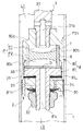
本実施の形態に係る緩衝器A2において、周波数感応部F2はピストン2の伸側室L1側に設けられ、周波数感応部F2のハウジング8がピストンロッド3の一部を構成する。詳しくは、ピストンロッド3がロッドガイドで支えられる軸部31と、この軸部31の先端部に連結される有頂筒状のケース80と、このケース80の開口端部を覆うとともにピストン2が装着されるピストン保持部81とを備え、ケース80とピストン保持部81とを備えて上記ハウジング8が構成される。
In the shock absorber A2 according to the present embodiment, the frequency sensitive part F2 is provided on the side of the expansion side chamber L1 of the
ケース80は、軸部31の先端部外周に螺合する環状の頂部80aと、この頂部80aの外周から図4中下方へ延びる筒部80bとを有し、この筒部80bの図4中下端部となる先端部内周に螺子溝が形成されている。また、ピストン保持部81は、上記螺子溝を利用して筒部80bの内周に螺合する蓋部81aと、この蓋部81aの中心部から図4中下方へ延びる取付軸81bとを有する。
The
そして、ピストン2の一方側にリーフバルブ21を重ね、ピストン2の他方側にリーフバルブ20を重ね、これらの中心孔にリーフバルブ21側から取付軸81bを挿通し、当該取付軸81bの先端にピストンナット32を螺合する。すると、ピストン2及びリーフバルブ20,21がその内周部を蓋部81aとピストンナット32との間に挟まれて固定される。本実施の形態では、蓋部81aがバルブストッパとしても機能する。
Then, the
また、周波数感応部F2は、ケース80とピストン保持部81とを有して構成される上記ハウジング8と、このハウジング8内に収容される筒6と、この筒6の内周に取り付けられる弾性部材7とを備える。筒6は、ケース80の筒部80b内に挿入されて、外周を当該筒部80bで支えられる。また、筒6は、一実施の形態と同様に金属製であり、その内周に弾性部材7が焼付けにより取り付けられている。弾性部材7も一実施の形態と同様に、ゴム等のエラストマーであり、筒6の軸方向の中央部を隙間なく埋めている。
The frequency sensitive portion F2 includes the
そして、ケース80と蓋部81aとで囲われるハウジング8の内部であって筒6の内側に圧力室Pが形成され、この圧力室Pが弾性部材7により図4中上側の第一室P1と図4中下側の第二室P2に区画される。第一室P1は、軸部31の先端から側部にかけて形成される通孔31aにより伸側室L1と連通され、第二室P2は、ピストン保持部81の蓋部81aから取付軸81bにかけての中心を貫通する通孔81cにより圧側室L2と連通される。そして、軸部31の先端部内周には有頂筒状の絞り部材30が嵌合し、当該絞り部材30により通孔31aの一部を絞ってオリフィスOを形成する。
A pressure chamber P is formed inside the
さらに、ケース80に弾性部材7付きの筒6を挿入してから筒部80bにピストン保持部81を螺合すると、ケース80の頂部80aとピストン保持部81の蓋部81aとで筒6が挟まれて固定される。このように筒6が固定されると、筒6の一端が頂部80aに押し付けられ、他端が蓋部81aに押し付けられるので、筒6の内側の液体が外周側に流出するのを防ぎ、第一室P1と第二室P2が筒6の外周とハウジング8との隙間を介して連通されるのを防止する。
Further, when the
上記筒部80bの肉厚は、当該筒部80bの内周に設けた段部80cを境に先端側が薄く、末端側が厚くなっており、先端側の内周にピストン保持部81を螺合するための螺子溝が形成されている。さらに、筒部80bにおいて肉厚が厚い部分の軸方向長さが筒6の軸方向長さよりも短いので、筒部80bにピストン保持部81を螺合したとき、蓋部81aが段部80cに干渉せず、筒6に確実に軸方向に力を加えられる。
The wall thickness of the
以下、本実施の形態に係る緩衝器A2の作用効果について説明する。 Hereinafter, the function and effect of the shock absorber A2 according to the present embodiment will be described.
本実施の形態において、オリフィスOは、伸側室L1と第一室P1とを連通する通孔31aの途中に設けられている。さらに、オリフィスOは軸部31の内周に嵌合し、通孔31aの途中に設けられる絞り部材30に形成されている。よって、オリフィスOを形成するための加工が容易である。さらに、オリフィスOによる抵抗を変更したい場合には、開口面積の異なるオリフィスOを有する他の絞り部材30に変更すればよくチューニングし易い。しかし、オリフィスOは、伸側室L1と第一室P1とを連通する流路と、圧側室L2と第二室P2とを連通する流路の何れに設けられていてもよい。例えば、図5には、ハウジング8におけるケース80の頂部80aにオリフィスOを設けた周波数感応部F20を示している。また、図6には、筒6と蓋部81aとの間に挟まれて固定されたプレート33にオリフィスOを設けた周波数感応部F21を示している。
In the present embodiment, the orifice O is provided in the middle of the through
また、本実施の形態において、緩衝器A2は、内周に弾性部材7が焼付けにより一体化された筒6と、この筒6を軸方向の両側から挟み込み、内部に圧力室Pが形成されるハウジング8とを備える。当該構成によれば、弾性部材7が筒6に焼付けにより一体化されているので、弾性部材7を筒6に強固に接着できて、弾性部材7が筒6内でずれたり、筒6から外れたりするのを容易且つ確実に防止できる。加えて、弾性部材7と筒6との間に隙間ができるのを防止できる。また、筒6を軸方向の両側からハウジング8で挟み込んでいるので、筒6の軸方向の両端部をハウジング8に密着させて、これらの間を容易に塞げる。つまり、上記構成によれば、弾性部材7で圧力室Pを区画するのを、容易且つ安価に実現できる。
Further, in the present embodiment, the shock absorber A2 has a
なお、弾性部材7の取付方法は焼付けに限られず、適宜変更できる。例えば、弾性部材7を環状のシート状にし、その外周部をリング等で筒6の内周に押し付けるようにしてもよい。このように弾性部材7を取り付ける場合には、筒6を廃し、ケース80の筒部80b内周に直接弾性部材7を取り付けてもよい。また、上記筒部80bの内周に弾性部材7を焼付けにより直接取り付けてもよい。この場合、頂部80aと筒部80bが個別に形成された後、嵌合、螺合、溶接等でハウジング8として一体化すると、弾性部材7をハウジング8の内周に焼付けにより容易に取り付けられる。そして、このような変更は、オリフィスOの位置によらず可能である。
The method of attaching the
また、本実施の形態において、緩衝器A2は、シリンダ1と、このシリンダ1内に移動自在に挿入されてシリンダ1内を伸側室(一方の作動室)L1と圧側室(他方の作動室)L2に区画するピストン2と、伸側室L1と圧側室L2を連通する伸側減衰通路2a(減衰通路)及び圧側減衰通路2b(減衰通路)と、伸側室L1と圧側室L2に連通される圧力室Pと、この圧力室Pを伸側室L1に連通される第一室P1と、圧側室L2に連通される第二室P2とに区画する弾性部材7とを備える。
Further, in the present embodiment, the shock absorber A2 is a
上記構成によれば、緩衝器A2が伸縮作動する際に弾性部材7が弾性変形して第一室P1と第二室P2の容積比が変化し、弾性変形量に応じて圧力室P内の液体が第一室P1と第二室P2へ出入りするため、見掛け上、圧力室Pを介して伸側室L1と圧側室L2の間を液体が移動したようになる。この見掛け上の流量は上記弾性変形量に応じて変化し、この流量変化に応じて伸側減衰通路2a及び圧側減衰通路2bの流量が変わるので、入力される振動の周波数に感応して高周波振動入力時に減衰力を低減させる効果を得られる。よって、緩衝器A2は、車両が旋回中等の入力振動周波数が低い場面においては高い減衰力を発揮し、車両が路面の凹凸を通過するような入力振動周波数が高い場面においては低い減衰力を発揮して、車両における乗り心地を向上できる。また、弾性部材7のばね定数は、素材又は厚みの変更等により調整できる。
According to the above configuration, when the shock absorber A2 expands and contracts, the
さらに、上記緩衝器A2では、フリーピストンとコイルばねの両方を必要とする従来の緩衝器と比較して、ハウジング8の軸方向長さを短くできる。したがって、ピストンロッド3にハウジング8を設けたとしても、緩衝器A2の軸方向長さが長くなるのを抑制して、緩衝器A2の搭載性を良好にできる。さらに、上記緩衝器A2では、圧力室Pを区画する隔壁を弾性部材7にして、摺動させない構造にしているので、高い加工精度が要求されず、部品自体を安価にできる。よって、上記緩衝器A2によれば、周波数に応じた減衰力を発揮できるとともに、コストを低減できる。
Further, in the shock absorber A2, the axial length of the
なお、上記緩衝器A2は、ピストンロッド3がピストン2の一方側にのみ延びる片ロッド型であるが、ピストンロッド3がピストン2の両方に延びる両ロッド型であってもよい。
The shock absorber A2 is a single rod type in which the
また、上記緩衝器A2は、単筒型であり、シリンダ1に出入りするピストンロッド出没体積分のシリンダ内容積変化を気室で補償するが、シリンダ1の外周にアウターシェルを設けて複筒型に設定されてもよい。このように緩衝器A2が複筒型である場合、アウターシェルとシリンダ1との間に液体を貯留するリザーバを形成し、当該リザーバでシリンダ内容積変化を補償するようにしてもよい。
Further, the shock absorber A2 is a single cylinder type, and the cylinder inner volume change corresponding to the piston rod retracted volume moving in and out of the
そして、前述のような変更は、オリフィスOの位置、及び弾性部材7の取付方法によらず可能である。
The above-described changes can be made regardless of the position of the orifice O and the attachment method of the
以上、本発明の好ましい実施の形態を詳細に説明したが、特許請求の範囲から逸脱しない限り、改造、変形および変更が可能である。 The preferred embodiments of the present invention have been described above in detail, but modifications, variations, and changes can be made without departing from the scope of the claims.
A1,A2・・・緩衝器、L1・・・伸側室(一方の作動室)、L2・・・圧側室(他方の作動室)、P・・・圧力室、P1・・・第一室、P2・・・第二室、1・・・シリンダ、2・・・ピストン、2a・・・伸側減衰通路(減衰通路)、2b・・・圧側減衰通路(減衰通路)、5,8・・・ハウジング、6・・・筒、7・・・弾性部材
A1, A2... shock absorber, L1... extension side chamber (one working chamber), L2... pressure side chamber (other working chamber), P... pressure chamber, P1... first chamber, P2... second chamber, 1... cylinder, 2... piston, 2a... extension side damping passage (damping passage), 2b... compression side damping passage (damping passage), 5, 8...・Housing, 6... Cylinder, 7... Elastic member
Claims (1)
前記シリンダ内に移動自在に挿入されて前記シリンダ内を二つの作動室に区画するピストンと、
前記二つの作動室を連通する減衰通路と、
内部に前記二つの作動室に連通される圧力室が形成されるハウジングと、
前記ハウジングにより軸方向の両側から挟み込まれるとともに、内周に前記圧力室を一方の前記作動室に連通される第一室と他方の前記作動室に連通される第二室とに区画する弾性部材が焼付けにより一体化された状態となっている筒とを備える
ことを特徴とする緩衝器。 A cylinder,
A piston that is movably inserted into the cylinder and partitions the inside of the cylinder into two working chambers;
A damping passage that connects the two working chambers,
A housing in which the pressure chambers to be communicated with the two working chambers is formed inside,
An elastic member that is sandwiched by the housing from both sides in the axial direction and that divides the pressure chamber into an inner periphery into a first chamber that communicates with one of the working chambers and a second chamber that communicates with the other of the working chambers. A shock absorber, characterized in that the shock absorber has a cylinder that is integrated by baking .
Priority Applications (6)
| Application Number | Priority Date | Filing Date | Title |
|---|---|---|---|
| JP2016076256A JP6709099B2 (en) | 2016-04-06 | 2016-04-06 | Shock absorber |
| EP17779162.1A EP3441640A1 (en) | 2016-04-06 | 2017-04-05 | Shock absorber |
| PCT/JP2017/014192 WO2017175784A1 (en) | 2016-04-06 | 2017-04-05 | Shock absorber |
| KR1020187028240A KR20180118735A (en) | 2016-04-06 | 2017-04-05 | buffer |
| US16/090,866 US20190107170A1 (en) | 2016-04-06 | 2017-04-05 | Shock absorber |
| CN201780021514.7A CN108884897A (en) | 2016-04-06 | 2017-04-05 | buffer |
Applications Claiming Priority (1)
| Application Number | Priority Date | Filing Date | Title |
|---|---|---|---|
| JP2016076256A JP6709099B2 (en) | 2016-04-06 | 2016-04-06 | Shock absorber |
Publications (2)
| Publication Number | Publication Date |
|---|---|
| JP2017187109A JP2017187109A (en) | 2017-10-12 |
| JP6709099B2 true JP6709099B2 (en) | 2020-06-10 |
Family
ID=60001054
Family Applications (1)
| Application Number | Title | Priority Date | Filing Date |
|---|---|---|---|
| JP2016076256A Active JP6709099B2 (en) | 2016-04-06 | 2016-04-06 | Shock absorber |
Country Status (6)
| Country | Link |
|---|---|
| US (1) | US20190107170A1 (en) |
| EP (1) | EP3441640A1 (en) |
| JP (1) | JP6709099B2 (en) |
| KR (1) | KR20180118735A (en) |
| CN (1) | CN108884897A (en) |
| WO (1) | WO2017175784A1 (en) |
Cited By (1)
| Publication number | Priority date | Publication date | Assignee | Title |
|---|---|---|---|---|
| KR102339177B1 (en) * | 2020-12-07 | 2021-12-14 | 한화시스템 주식회사 | Complex Stopper Assembly |
Families Citing this family (5)
| Publication number | Priority date | Publication date | Assignee | Title |
|---|---|---|---|---|
| WO2020137207A1 (en) * | 2018-12-25 | 2020-07-02 | 日立オートモティブシステムズ株式会社 | Shock absorber |
| CN114542647A (en) * | 2020-11-27 | 2022-05-27 | 比亚迪股份有限公司 | Valve train assembly for shock absorber and shock absorber with same |
| CN113983106B (en) * | 2021-11-25 | 2022-05-24 | 宁波瑞丰汽车零部件有限公司 | Low-speed flow adjustable shock absorber piston |
| WO2023120576A1 (en) * | 2021-12-24 | 2023-06-29 | 日立Astemo株式会社 | Damping force generation device |
| US12454991B2 (en) | 2022-01-13 | 2025-10-28 | Advanced Suspension Technology Llc | Space saving pressure relief valves for suspension dampers |
Family Cites Families (21)
| Publication number | Priority date | Publication date | Assignee | Title |
|---|---|---|---|---|
| US4502575A (en) * | 1980-08-13 | 1985-03-05 | Nissan Motor Company, Limited | Shock absorber |
| US4955460A (en) * | 1988-08-01 | 1990-09-11 | Monroe Auto Equipment Company | Control valve for shock absorbers |
| GB2250080B (en) * | 1990-10-19 | 1994-08-17 | Tokico Ltd | Hydraulic shock absorber |
| DE69415778T2 (en) * | 1993-11-13 | 1999-05-20 | Delphi France Automotive Systems Immeuble Vision Defense, La Garenne-Colombes | Shock absorber |
| US6561326B2 (en) * | 2000-05-04 | 2003-05-13 | Krupp Bilstein Gmbh | Amplitude-attenuating dashpot |
| EP2330473B2 (en) | 2001-06-12 | 2019-06-19 | iRobot Corporation | Mobile robot |
| DE10300107B3 (en) * | 2003-01-07 | 2004-05-13 | Thyssenkrupp Bilstein Gmbh | Hydraulic shock absorber device has annular piston displaced within separate space connected hydraulically in parallel with damping piston |
| EP1698797B1 (en) * | 2003-07-08 | 2011-08-03 | ThyssenKrupp Bilstein Suspension GmbH | Vibration damper with amplitude-dependent damping |
| DE102004015065B4 (en) * | 2004-03-25 | 2015-02-05 | Zf Friedrichshafen Ag | Vibration damper with amplitude-dependent damping force |
| DE102004018990B3 (en) * | 2004-04-20 | 2005-11-17 | Thyssenkrupp Bilstein Gmbh | Shock absorbers with amplitude-dependent damping |
| EP1731792B1 (en) * | 2005-06-06 | 2008-02-27 | Kayaba Industry Co., Ltd. | Shock absorber |
| JP4726049B2 (en) * | 2005-06-06 | 2011-07-20 | カヤバ工業株式会社 | Shock absorber |
| JP4644572B2 (en) | 2005-09-12 | 2011-03-02 | カヤバ工業株式会社 | Shock absorber |
| SI2152997T1 (en) * | 2007-05-18 | 2015-07-31 | Faringosi-Hinges S.R.L. | Door hinge |
| JP2009079710A (en) * | 2007-09-26 | 2009-04-16 | Showa Corp | Damping force adjustment structure of hydraulic shock absorber |
| US20090145708A1 (en) * | 2007-12-05 | 2009-06-11 | Mando Corporation | Shock absorber |
| JP2010002025A (en) * | 2008-06-23 | 2010-01-07 | Unimatec Co Ltd | Vibration-proof roller |
| JP5809801B2 (en) * | 2010-12-28 | 2015-11-11 | 日立オートモティブシステムズ株式会社 | Shock absorber |
| JP6027451B2 (en) * | 2013-01-25 | 2016-11-16 | Kyb株式会社 | Shock absorber |
| JP5961130B2 (en) * | 2013-03-22 | 2016-08-02 | Kyb株式会社 | Shock absorber |
| KR101798555B1 (en) * | 2013-11-27 | 2017-11-16 | 주식회사 만도 | Shock abasorber |
-
2016
- 2016-04-06 JP JP2016076256A patent/JP6709099B2/en active Active
-
2017
- 2017-04-05 WO PCT/JP2017/014192 patent/WO2017175784A1/en not_active Ceased
- 2017-04-05 US US16/090,866 patent/US20190107170A1/en not_active Abandoned
- 2017-04-05 KR KR1020187028240A patent/KR20180118735A/en not_active Withdrawn
- 2017-04-05 CN CN201780021514.7A patent/CN108884897A/en active Pending
- 2017-04-05 EP EP17779162.1A patent/EP3441640A1/en not_active Withdrawn
Cited By (1)
| Publication number | Priority date | Publication date | Assignee | Title |
|---|---|---|---|---|
| KR102339177B1 (en) * | 2020-12-07 | 2021-12-14 | 한화시스템 주식회사 | Complex Stopper Assembly |
Also Published As
| Publication number | Publication date |
|---|---|
| KR20180118735A (en) | 2018-10-31 |
| CN108884897A (en) | 2018-11-23 |
| WO2017175784A1 (en) | 2017-10-12 |
| US20190107170A1 (en) | 2019-04-11 |
| JP2017187109A (en) | 2017-10-12 |
| EP3441640A1 (en) | 2019-02-13 |
Similar Documents
| Publication | Publication Date | Title |
|---|---|---|
| JP6709099B2 (en) | Shock absorber | |
| CN104937304B (en) | Buffer unit | |
| JP6108550B2 (en) | Shock absorber | |
| CN105051403B (en) | Buffer device | |
| US9776468B2 (en) | Shock absorber | |
| JP5466437B2 (en) | Shock absorber | |
| CN104903612B (en) | Snubber | |
| JP5368917B2 (en) | Damping valve | |
| CN101305203A (en) | Single cylinder type hydraulic shock absorber for vehicles | |
| JP2012052630A (en) | Shock absorber | |
| JP6779027B2 (en) | Buffer and manufacturing method of buffer | |
| JP2001193782A (en) | Hydraulic shock absorber | |
| CN104541084A (en) | Buffer | |
| JPH08121524A (en) | shock absorber | |
| JP5690179B2 (en) | Shock absorber | |
| JP5142971B2 (en) | Shock absorber | |
| JP5831976B2 (en) | Shock absorber | |
| JP2010196842A (en) | Shock absorber | |
| JP6093599B2 (en) | Shock absorber | |
| JP6082277B2 (en) | Shock absorber | |
| JP2018054020A (en) | shock absorber | |
| JP2014181737A (en) | Shock absorber | |
| JP2019168096A (en) | Front fork | |
| JP2014074444A (en) | Buffer device | |
| JP2011220489A (en) | Shock absorber |
Legal Events
| Date | Code | Title | Description |
|---|---|---|---|
| A621 | Written request for application examination |
Free format text: JAPANESE INTERMEDIATE CODE: A621 Effective date: 20190220 |
|
| A131 | Notification of reasons for refusal |
Free format text: JAPANESE INTERMEDIATE CODE: A131 Effective date: 20200204 |
|
| A521 | Request for written amendment filed |
Free format text: JAPANESE INTERMEDIATE CODE: A523 Effective date: 20200402 |
|
| TRDD | Decision of grant or rejection written | ||
| A01 | Written decision to grant a patent or to grant a registration (utility model) |
Free format text: JAPANESE INTERMEDIATE CODE: A01 Effective date: 20200428 |
|
| A61 | First payment of annual fees (during grant procedure) |
Free format text: JAPANESE INTERMEDIATE CODE: A61 Effective date: 20200522 |
|
| R151 | Written notification of patent or utility model registration |
Ref document number: 6709099 Country of ref document: JP Free format text: JAPANESE INTERMEDIATE CODE: R151 |
|
| S533 | Written request for registration of change of name |
Free format text: JAPANESE INTERMEDIATE CODE: R313533 |
|
| R350 | Written notification of registration of transfer |
Free format text: JAPANESE INTERMEDIATE CODE: R350 |