WO2017175784A1 - Shock absorber - Google Patents
Shock absorber Download PDFInfo
- Publication number
- WO2017175784A1 WO2017175784A1 PCT/JP2017/014192 JP2017014192W WO2017175784A1 WO 2017175784 A1 WO2017175784 A1 WO 2017175784A1 JP 2017014192 W JP2017014192 W JP 2017014192W WO 2017175784 A1 WO2017175784 A1 WO 2017175784A1
- Authority
- WO
- WIPO (PCT)
- Prior art keywords
- chamber
- cylinder
- shock absorber
- pressure
- elastic member
- Prior art date
Links
Images


Classifications
-
- F—MECHANICAL ENGINEERING; LIGHTING; HEATING; WEAPONS; BLASTING
- F16—ENGINEERING ELEMENTS AND UNITS; GENERAL MEASURES FOR PRODUCING AND MAINTAINING EFFECTIVE FUNCTIONING OF MACHINES OR INSTALLATIONS; THERMAL INSULATION IN GENERAL
- F16F—SPRINGS; SHOCK-ABSORBERS; MEANS FOR DAMPING VIBRATION
- F16F9/00—Springs, vibration-dampers, shock-absorbers, or similarly-constructed movement-dampers using a fluid or the equivalent as damping medium
- F16F9/32—Details
- F16F9/3207—Constructional features
-
- F—MECHANICAL ENGINEERING; LIGHTING; HEATING; WEAPONS; BLASTING
- F16—ENGINEERING ELEMENTS AND UNITS; GENERAL MEASURES FOR PRODUCING AND MAINTAINING EFFECTIVE FUNCTIONING OF MACHINES OR INSTALLATIONS; THERMAL INSULATION IN GENERAL
- F16F—SPRINGS; SHOCK-ABSORBERS; MEANS FOR DAMPING VIBRATION
- F16F9/00—Springs, vibration-dampers, shock-absorbers, or similarly-constructed movement-dampers using a fluid or the equivalent as damping medium
- F16F9/32—Details
- F16F9/50—Special means providing automatic damping adjustment, i.e. self-adjustment of damping by particular sliding movements of a valve element, other than flexions or displacement of valve discs; Special means providing self-adjustment of spring characteristics
- F16F9/512—Means responsive to load action, i.e. static load on the damper or dynamic fluid pressure changes in the damper, e.g. due to changes in velocity
-
- B—PERFORMING OPERATIONS; TRANSPORTING
- B60—VEHICLES IN GENERAL
- B60G—VEHICLE SUSPENSION ARRANGEMENTS
- B60G13/00—Resilient suspensions characterised by arrangement, location or type of vibration dampers
- B60G13/02—Resilient suspensions characterised by arrangement, location or type of vibration dampers having dampers dissipating energy, e.g. frictionally
- B60G13/06—Resilient suspensions characterised by arrangement, location or type of vibration dampers having dampers dissipating energy, e.g. frictionally of fluid type
- B60G13/08—Resilient suspensions characterised by arrangement, location or type of vibration dampers having dampers dissipating energy, e.g. frictionally of fluid type hydraulic
-
- B—PERFORMING OPERATIONS; TRANSPORTING
- B60—VEHICLES IN GENERAL
- B60G—VEHICLE SUSPENSION ARRANGEMENTS
- B60G17/00—Resilient suspensions having means for adjusting the spring or vibration-damper characteristics, for regulating the distance between a supporting surface and a sprung part of vehicle or for locking suspension during use to meet varying vehicular or surface conditions, e.g. due to speed or load
- B60G17/06—Characteristics of dampers, e.g. mechanical dampers
- B60G17/08—Characteristics of fluid dampers
-
- F—MECHANICAL ENGINEERING; LIGHTING; HEATING; WEAPONS; BLASTING
- F16—ENGINEERING ELEMENTS AND UNITS; GENERAL MEASURES FOR PRODUCING AND MAINTAINING EFFECTIVE FUNCTIONING OF MACHINES OR INSTALLATIONS; THERMAL INSULATION IN GENERAL
- F16F—SPRINGS; SHOCK-ABSORBERS; MEANS FOR DAMPING VIBRATION
- F16F9/00—Springs, vibration-dampers, shock-absorbers, or similarly-constructed movement-dampers using a fluid or the equivalent as damping medium
- F16F9/10—Springs, vibration-dampers, shock-absorbers, or similarly-constructed movement-dampers using a fluid or the equivalent as damping medium using liquid only; using a fluid of which the nature is immaterial
- F16F9/14—Devices with one or more members, e.g. pistons, vanes, moving to and fro in chambers and using throttling effect
- F16F9/16—Devices with one or more members, e.g. pistons, vanes, moving to and fro in chambers and using throttling effect involving only straight-line movement of the effective parts
- F16F9/18—Devices with one or more members, e.g. pistons, vanes, moving to and fro in chambers and using throttling effect involving only straight-line movement of the effective parts with a closed cylinder and a piston separating two or more working spaces therein
- F16F9/19—Devices with one or more members, e.g. pistons, vanes, moving to and fro in chambers and using throttling effect involving only straight-line movement of the effective parts with a closed cylinder and a piston separating two or more working spaces therein with a single cylinder and of single-tube type
-
- F—MECHANICAL ENGINEERING; LIGHTING; HEATING; WEAPONS; BLASTING
- F16—ENGINEERING ELEMENTS AND UNITS; GENERAL MEASURES FOR PRODUCING AND MAINTAINING EFFECTIVE FUNCTIONING OF MACHINES OR INSTALLATIONS; THERMAL INSULATION IN GENERAL
- F16F—SPRINGS; SHOCK-ABSORBERS; MEANS FOR DAMPING VIBRATION
- F16F9/00—Springs, vibration-dampers, shock-absorbers, or similarly-constructed movement-dampers using a fluid or the equivalent as damping medium
- F16F9/32—Details
- F16F9/3207—Constructional features
- F16F9/3214—Constructional features of pistons
-
- B—PERFORMING OPERATIONS; TRANSPORTING
- B60—VEHICLES IN GENERAL
- B60G—VEHICLE SUSPENSION ARRANGEMENTS
- B60G2206/00—Indexing codes related to the manufacturing of suspensions: constructional features, the materials used, procedures or tools
- B60G2206/01—Constructional features of suspension elements, e.g. arms, dampers, springs
- B60G2206/40—Constructional features of dampers and/or springs
- B60G2206/41—Dampers
-
- B—PERFORMING OPERATIONS; TRANSPORTING
- B60—VEHICLES IN GENERAL
- B60G—VEHICLE SUSPENSION ARRANGEMENTS
- B60G2500/00—Indexing codes relating to the regulated action or device
- B60G2500/10—Damping action or damper
-
- F—MECHANICAL ENGINEERING; LIGHTING; HEATING; WEAPONS; BLASTING
- F16—ENGINEERING ELEMENTS AND UNITS; GENERAL MEASURES FOR PRODUCING AND MAINTAINING EFFECTIVE FUNCTIONING OF MACHINES OR INSTALLATIONS; THERMAL INSULATION IN GENERAL
- F16F—SPRINGS; SHOCK-ABSORBERS; MEANS FOR DAMPING VIBRATION
- F16F2228/00—Functional characteristics, e.g. variability, frequency-dependence
- F16F2228/04—Frequency effects
-
- F—MECHANICAL ENGINEERING; LIGHTING; HEATING; WEAPONS; BLASTING
- F16—ENGINEERING ELEMENTS AND UNITS; GENERAL MEASURES FOR PRODUCING AND MAINTAINING EFFECTIVE FUNCTIONING OF MACHINES OR INSTALLATIONS; THERMAL INSULATION IN GENERAL
- F16F—SPRINGS; SHOCK-ABSORBERS; MEANS FOR DAMPING VIBRATION
- F16F2228/00—Functional characteristics, e.g. variability, frequency-dependence
- F16F2228/06—Stiffness
- F16F2228/066—Variable stiffness
-
- F—MECHANICAL ENGINEERING; LIGHTING; HEATING; WEAPONS; BLASTING
- F16—ENGINEERING ELEMENTS AND UNITS; GENERAL MEASURES FOR PRODUCING AND MAINTAINING EFFECTIVE FUNCTIONING OF MACHINES OR INSTALLATIONS; THERMAL INSULATION IN GENERAL
- F16F—SPRINGS; SHOCK-ABSORBERS; MEANS FOR DAMPING VIBRATION
- F16F9/00—Springs, vibration-dampers, shock-absorbers, or similarly-constructed movement-dampers using a fluid or the equivalent as damping medium
- F16F9/06—Springs, vibration-dampers, shock-absorbers, or similarly-constructed movement-dampers using a fluid or the equivalent as damping medium using both gas and liquid
- F16F9/061—Mono-tubular units
-
- F—MECHANICAL ENGINEERING; LIGHTING; HEATING; WEAPONS; BLASTING
- F16—ENGINEERING ELEMENTS AND UNITS; GENERAL MEASURES FOR PRODUCING AND MAINTAINING EFFECTIVE FUNCTIONING OF MACHINES OR INSTALLATIONS; THERMAL INSULATION IN GENERAL
- F16F—SPRINGS; SHOCK-ABSORBERS; MEANS FOR DAMPING VIBRATION
- F16F9/00—Springs, vibration-dampers, shock-absorbers, or similarly-constructed movement-dampers using a fluid or the equivalent as damping medium
- F16F9/06—Springs, vibration-dampers, shock-absorbers, or similarly-constructed movement-dampers using a fluid or the equivalent as damping medium using both gas and liquid
- F16F9/064—Units characterised by the location or shape of the expansion chamber
- F16F9/065—Expansion chamber provided on the upper or lower end of a damper, separately there from or laterally on the damper
-
- F—MECHANICAL ENGINEERING; LIGHTING; HEATING; WEAPONS; BLASTING
- F16—ENGINEERING ELEMENTS AND UNITS; GENERAL MEASURES FOR PRODUCING AND MAINTAINING EFFECTIVE FUNCTIONING OF MACHINES OR INSTALLATIONS; THERMAL INSULATION IN GENERAL
- F16F—SPRINGS; SHOCK-ABSORBERS; MEANS FOR DAMPING VIBRATION
- F16F9/00—Springs, vibration-dampers, shock-absorbers, or similarly-constructed movement-dampers using a fluid or the equivalent as damping medium
- F16F9/10—Springs, vibration-dampers, shock-absorbers, or similarly-constructed movement-dampers using a fluid or the equivalent as damping medium using liquid only; using a fluid of which the nature is immaterial
- F16F9/14—Devices with one or more members, e.g. pistons, vanes, moving to and fro in chambers and using throttling effect
- F16F9/16—Devices with one or more members, e.g. pistons, vanes, moving to and fro in chambers and using throttling effect involving only straight-line movement of the effective parts
- F16F9/18—Devices with one or more members, e.g. pistons, vanes, moving to and fro in chambers and using throttling effect involving only straight-line movement of the effective parts with a closed cylinder and a piston separating two or more working spaces therein
- F16F9/182—Devices with one or more members, e.g. pistons, vanes, moving to and fro in chambers and using throttling effect involving only straight-line movement of the effective parts with a closed cylinder and a piston separating two or more working spaces therein comprising a hollow piston rod
-
- F—MECHANICAL ENGINEERING; LIGHTING; HEATING; WEAPONS; BLASTING
- F16—ENGINEERING ELEMENTS AND UNITS; GENERAL MEASURES FOR PRODUCING AND MAINTAINING EFFECTIVE FUNCTIONING OF MACHINES OR INSTALLATIONS; THERMAL INSULATION IN GENERAL
- F16F—SPRINGS; SHOCK-ABSORBERS; MEANS FOR DAMPING VIBRATION
- F16F9/00—Springs, vibration-dampers, shock-absorbers, or similarly-constructed movement-dampers using a fluid or the equivalent as damping medium
- F16F9/32—Details
- F16F9/3207—Constructional features
- F16F9/3228—Constructional features of connections between pistons and piston rods
-
- F—MECHANICAL ENGINEERING; LIGHTING; HEATING; WEAPONS; BLASTING
- F16—ENGINEERING ELEMENTS AND UNITS; GENERAL MEASURES FOR PRODUCING AND MAINTAINING EFFECTIVE FUNCTIONING OF MACHINES OR INSTALLATIONS; THERMAL INSULATION IN GENERAL
- F16F—SPRINGS; SHOCK-ABSORBERS; MEANS FOR DAMPING VIBRATION
- F16F9/00—Springs, vibration-dampers, shock-absorbers, or similarly-constructed movement-dampers using a fluid or the equivalent as damping medium
- F16F9/32—Details
- F16F9/3271—Assembly or repair
Definitions
- the present invention relates to a shock absorber.
- a shock absorber is interposed between a vehicle body and an axle and used for the purpose of suppressing vehicle body vibration.
- the shock absorber includes a cylinder, a piston slidably inserted into the cylinder, one end connected to the piston, and the other end to the cylinder.
- a piston rod extending outside, an upper chamber and a lower chamber formed in the cylinder and defined by the piston, a first passage and a second passage communicating the upper chamber and the lower chamber, and provided in the middle of the second passage
- a pressure chamber a housing in which the pressure chamber is formed and attached to the tip of the piston rod, and a slidably inserted into the housing, the pressure chamber being communicated with the lower chamber and the one chamber and the upper chamber being communicated
- a free piston that is partitioned into the other chamber, and a coil spring that exerts an urging force that suppresses displacement of the free piston with respect to the pressure chamber.
- the upper chamber and the lower chamber are not directly communicated with each other via the second passage, but when the free piston moves, the volume ratio of the one chamber to the other chamber in the pressure chamber is increased. Since the liquid in the pressure chamber moves in and out of the upper chamber and the lower chamber according to the amount of movement of the free piston, it apparently behaves as if the upper chamber and the lower chamber are connected via the second passage.
- this shock absorber can generate a high damping force for low frequency vibration input and a low damping force for high frequency vibration input. Therefore, in a scene where the input vibration frequency is low such as when the vehicle is turning, the shock absorber can generate a high damping force, and in a scene where the input vibration frequency is high such that the vehicle passes through the unevenness of the road surface, the shock absorber Therefore, it is possible to reliably generate a low damping force and improve the riding comfort in the vehicle.
- the above-described conventional shock absorber has a structure in which the free piston that defines the pressure chamber is slidably contacted with the inner periphery of the housing. In such a sliding portion where the two members are slidably contacted, high processing accuracy is required, so that the components themselves are expensive.
- an object of the present invention is to provide a shock absorber that can exhibit a damping force corresponding to a frequency and can reduce costs.
- the present invention provides a damping passage that communicates two working chambers defined by a piston, a pressure chamber that communicates with the two working chambers, and the pressure chamber as one working chamber. And an elastic member that is divided into a first chamber communicated with and a second chamber communicated with the other working chamber.
- the shock absorber expands and contracts
- the elastic member elastically deforms and the volume ratio between the first chamber and the second chamber changes, and the liquid in the pressure chamber changes from the first chamber according to the amount of elastic deformation.
- the liquid In order to enter and exit the second chamber, the liquid apparently moves between the two working chambers via the pressure chamber.
- the partition wall defining the pressure chamber is made of an elastic member and does not slide, high processing accuracy is not required, and the parts themselves can be made inexpensive.
- FIG. 1 is a front view of the shock absorber according to the first embodiment of the present invention, partially cut away.
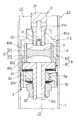
- FIG. 2 is an enlarged longitudinal sectional view showing a part of FIG.
- FIG. 3 is a longitudinal sectional view showing a modified example of the shock absorber according to the first embodiment of the present invention and showing an enlarged portion of the change.
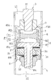
- FIG. 4 is an enlarged longitudinal sectional view showing a part of the shock absorber according to the second embodiment of the present invention.
- FIG. 5 is the longitudinal cross-sectional view which showed the 1st modification of the buffer which concerns on 2nd embodiment of this invention, and expanded and showed the changed part.
- FIG. 6 is the longitudinal cross-sectional view which showed the 2nd modification of the buffer which concerns on 2nd embodiment of this invention, and expanded and showed the changed part.
- a shock absorber A1 according to the first embodiment of the present invention shown in FIG. 1 is interposed between a vehicle body and an axle in a vehicle to exhibit a damping force and suppress vibrations of the vehicle body.
- the shock absorber A1 includes a cylinder 1, a piston 2 slidably inserted into the cylinder 1, a piston rod 3 having one end connected to the piston 2 and the other end extending outside the cylinder 1, and a piston rod 3 1 is provided with a frequency sensitive portion F1 attached to the lower side of the piston 2 in FIG.
- the cylinder 1 is connected to one of the vehicle body and the axle via the attachment member 10, and the piston rod 3 is connected to the other of the vehicle body and the axle via the attachment member (not shown). Therefore, when the vehicle body and the axle are separated from each other, the piston rod 3 is retracted from the cylinder 1 and the shock absorber A1 is extended. On the contrary, when the vehicle body and the axle are close to each other, the piston rod 3 enters the cylinder 1 and the shock absorber A1. Operates to contract.
- an extension side chamber L1 and a pressure side chamber L2 defined by the piston 2 are formed, and an air chamber G defined by the sliding partition wall 4 and the pressure side chamber L2 is formed.
- the extension side chamber L1 and the compression side chamber L2 are working chambers and are filled with a liquid such as hydraulic oil. Gas is sealed in the air chamber G.
- the cylinder 1 is formed in a bottomed cylindrical shape, and a rod guide 11 that supports the piston rod 3 so as to be movable in the axial direction is provided at the opening end of the cylinder 1.
- the space between the cylinder 1 and the piston rod 3 is sealed by a seal member 12 stacked on the rod guide 11. Therefore, the liquid and gas in the cylinder 1 do not leak out of the cylinder 1, and the inside of the cylinder 1 is partitioned from the outside air.
- the piston rod 3 is a single rod type in which only the expansion side chamber L1 is inserted, and the change in volume in the cylinder corresponding to the piston rod protruding and retracting volume is compensated by the air chamber G.
- the piston rod withdrawal volume integral cylinder internal volume increases, but the sliding partition 4 moves upward in FIG. G expands to compensate for the cylinder volume increase.
- the shock absorber A1 in which the piston rod 3 enters the cylinder 1 is contracted, the piston rod entry volume integral cylinder volume decreases, but the sliding partition 4 moves downward in FIG. Reduce to compensate for the volume reduction in the cylinder.
- the piston 2 is provided with an expansion side attenuation passage 2a and a compression side attenuation passage 2b as attenuation passages that connect the expansion side chamber L1 and the compression side chamber L2.
- Leaf valves 20 and 21 are provided as damping force generating elements at the outlets of the extension side damping passage 2a and the compression side damping passage 2b.
- the leaf valve 20 gives resistance to the flow of liquid passing through the expansion side attenuation passage 2a
- the leaf valve 21 gives resistance to the flow of liquid passing through the compression side attenuation passage 2b.
- the leaf valve 20 is laminated on the lower side of the piston 2 in FIG.
- annular valve stopper 22 is laminated above the leaf valve 21 in FIG.
- the piston 2, the leaf valves 20, 21 and the valve stopper 22 all have a central hole that penetrates the central portion. Then, the leaf valve 21 and the valve stopper 22 are overlapped in this order on one side of the piston 2, the leaf valve 20 is overlapped on the other side of the piston 2, and the small diameter portion 3a ( 2) is inserted, and a housing 5 (to be described later) of the frequency sensitive portion F1 is screwed to the tip of the small diameter portion 3a. Then, the piston 2, the leaf valves 20 and 21, and the valve stopper 22 are fixed by sandwiching the inner peripheral portion between the step 3 b (FIG. 2) of the piston rod 3 and the housing 5. Thus, the housing 5 also functions as a piston nut for attaching the piston 2 and valves stacked on the piston 2 to the piston rod 3.
- the frequency sensitive part F ⁇ b> 1 includes the housing 5, a cylinder 6 accommodated in the housing 5, and an elastic member 7 attached to the inner periphery of the cylinder 6.
- the housing 5 has a bottomed cylindrical case 50 having an annular bottom portion 50a and a cylindrical portion 50b that rises upward in FIG. 2 from the outer periphery of the bottom portion 50a, and a tip that is the upper end portion of the cylindrical portion 50b in FIG. And an annular lid 51 that is fixed to the outer periphery of the piston rod 3 and screwed onto the outer periphery of the piston rod 3.
- the cylinder 6 is inserted into the cylinder part 50b of the case 50, and the outer periphery is supported by the cylinder part 50b.
- the cylinder 6 is made of metal, and an elastic member 7 is attached to the inner periphery thereof by baking.
- the elastic member 7 is an elastomer such as rubber, and fills the axial central portion of the cylinder 6 without a gap.
- a pressure chamber P is formed inside the cylinder 6 inside the housing 5 surrounded by the case 50 and the lid portion 51, and this pressure chamber P is connected to the first chamber P 1 on the upper side in FIG. It is divided into the second chamber P2 on the lower side in FIG.
- the first chamber P1 communicates with the expansion side chamber L1 through a through hole 3c formed from the tip of the piston rod 3 to the side, and the second chamber P2 is compressed by a hole 50c penetrating the center of the bottom 50a of the case 50. It communicates with the room L2.
- a crested cylindrical throttling member 30 is fitted to the inner periphery of the tip of the piston rod 3, and the orifice O is formed by throttling a part of the through hole 3 c by the throttling member 30.
- the lid 51 when the lid 51 is inserted after the cylinder 6 with the elastic member 7 is inserted into the case 50 and the tip of the cylinder 50b of the case 50 is crimped inward, the lid 51 and the bottom 50a of the case 50 The cylinder 6 is sandwiched and fixed.
- the cylinder 6 is fixed in this way, one end of the cylinder 6 is pressed against the lid portion 51 and the other end is pressed against the bottom 50a, so that the liquid inside the cylinder 6 is prevented from flowing out to the outer peripheral side.
- the first chamber P ⁇ b> 1 and the second chamber P ⁇ b> 2 are prevented from communicating with each other through a gap between the outer periphery of the cylinder 6 and the housing 5.
- the thickness of the cylindrical part 50b is thin at the tip side and thick at the end side with respect to the step part 50d provided on the inner periphery of the cylindrical part 50b, so that caulking is easy. Further, since the axial length of the thick portion of the cylindrical portion 50b is shorter than the axial length of the cylindrical portion 6, when the tip of the cylindrical portion 50b is crimped, the lid portion 51 interferes with the step portion 50d. Therefore, a force can be reliably applied to the cylinder 6 in the axial direction.
- the housing 5, the cylinder 6 and the elastic member 7 are integrated with the piston rod 3 in an integrated state.
- the hole 50c provided in the bottom 50a of the case 50 has a hexagonal cross section, and when a tool is inserted into the hole 50c, relative rotation with the tool is prevented. Therefore, the hole 50c serves as a flow path that communicates the compression side chamber L2 and the second chamber P2, and is also used as a tool insertion hole that is used when the housing 5 is screwed to the piston rod 3.
- the operation of the shock absorber A1 will be described.
- the piston 2 moves upward in FIG. 1 relative to the cylinder 1, compresses the extension side chamber L1, and expands the compression side chamber L2.
- the pressure in the expansion side chamber L1 increases and simultaneously the pressure in the compression side chamber L2 decreases to generate a differential pressure therebetween.
- the liquid in the expansion side chamber L1 moves to the compression side chamber L2 through the expansion side attenuation passage 2a.
- this pressure is transmitted to the first chamber P1 through the through hole 3c and the orifice O, and the elastic member 7 is bent toward the second chamber P2.
- the volume of the first chamber P1 is increased, and the volume of the second chamber P2 is reduced accordingly, and the liquid in the second chamber P2 is pushed out to the pressure side chamber L2 through the hole 50c.
- the piston speed in the expansion / contraction operation of the shock absorber A1 is the same regardless of whether the vibration frequency input to the shock absorber A1 is low or high.
- the amplitude of the shock absorber A1 when a low frequency vibration is input is larger than the amplitude of the shock absorber A1 when a high frequency vibration is input.
- the amplitude is large, so the amount of liquid that moves between the extension side chamber L1 and the compression side chamber L2 during one period of vibration increases, The amount of deformation of the elastic member 7 increases.
- the elastic force of the elastic member 7 resisting the deformation is increased, and accordingly, a differential pressure is generated in the first chamber P1 and the second chamber P2, and the differential pressure between the extension side chamber L1 and the first chamber P1 and The pressure difference between the pressure side chamber L2 and the second chamber P2 is reduced, and the flow rate of the apparent liquid moving through the pressure chamber P is reduced. Since the apparent flow rate is small, the flow rate of the liquid moving through the expansion side attenuation passage 2a and the compression side attenuation passage 2b is increased, so that the damping force generated by the shock absorber A1 is maintained high.
- the amplitude is smaller than when low frequency vibration is input, so the amount of liquid that moves between the expansion side chamber L1 and the compression side chamber L2 during one vibration period is small.
- the deformation amount of the elastic member 7 is also small.
- the elastic force of the elastic member 7 that resists the deformation is reduced, and accordingly, the differential pressure between the first chamber P1 and the second chamber P2 is reduced, and the first chamber P1 and the second chamber P2 are almost at the same pressure.
- the differential pressure between the extension side chamber L1 and the first chamber P1 and the differential pressure between the compression side chamber L2 and the second chamber P2 become larger than those at the time of low frequency vibration input, and the above apparent flow rate is low frequency vibration input.
- the hole 50c communicating the compression side chamber L2 and the second chamber P2 has a hexagonal cross section. Therefore, although the hole 50c can be used as a tool insertion hole, the shape of the hole 50c can be changed as appropriate. For example, even when a pair of holes arranged in the diameter direction is formed in the bottom 50a of the case 50 in the housing 5, the same effect as described above can be obtained.
- the orifice O is provided in the middle of the through hole 3c that communicates the extension side chamber L1 and the first chamber P1. Further, the orifice O is formed in a throttle member 30 that is fitted to the inner periphery of the piston rod 3 and provided in the middle of the through hole 3c. Therefore, the process for forming the orifice O is easy. Further, when the resistance by the orifice O is desired to be changed, the tuning can be easily performed by changing to another throttle member 30 having the orifices O having different opening areas.
- the orifice O may be provided in any of a flow path that communicates the expansion side chamber L1 and the first chamber P1, and a flow path that communicates the compression side chamber L2 and the second chamber P2.
- FIG. 3 shows a frequency sensitive part F10 in which an orifice O is provided in the bottom 50a of the case 50 in the housing 5 instead of the hole 50c.
- the shock absorber A1 includes a cylinder 6 in which an elastic member 7 is integrated on the inner periphery by baking, and the cylinder 6 is sandwiched from both sides in the axial direction, and a pressure chamber P is formed inside. And a housing 5.
- the elastic member 7 since the elastic member 7 is integrated with the cylinder 6 by baking, the elastic member 7 can be firmly bonded to the cylinder 6 so that the elastic member 7 is displaced within the cylinder 6 or detached from the cylinder 6. Can be easily and reliably prevented. In addition, it is possible to prevent a gap from being formed between the elastic member 7 and the cylinder 6.
- both ends of the cylinder 6 in the axial direction are brought into close contact with the housing 5 so that the space between them can be easily closed. That is, according to the above configuration, it is possible to easily and inexpensively partition the pressure chamber P with the elastic member 7.
- the attachment method of the elastic member 7 is not limited to baking, and can be changed as appropriate.
- the elastic member 7 may be formed into an annular sheet shape, and the outer peripheral portion thereof may be pressed against the inner periphery of the cylinder 6 with a ring or the like.
- the cylinder 6 may be abolished and the elastic member 7 may be directly attached to the inner periphery of the cylinder part 50b of the case 50.
- the elastic member 7 may be directly attached to the inner periphery of the cylindrical portion 50b by baking.
- the elastic member 7 can be easily attached to the inner periphery of the housing 5 by baking. Such a change is possible regardless of the shape of the hole 50c and the position of the orifice O.
- the shock absorber A1 is movably inserted into the cylinder 1 and the cylinder 1, and extends in the cylinder 1 through the expansion side chamber (one working chamber) L1 and the pressure side chamber (the other working chamber).
- the piston 2 partitioned into L2, the extension side damping passage 2a (attenuation passage) and the pressure side attenuation passage 2b (attenuation passage) communicating with the extension side chamber L1 and the pressure side chamber L2, and the pressure communicated with the extension side chamber L1 and the pressure side chamber L2.
- a chamber P, and an elastic member 7 that partitions the pressure chamber P into a first chamber P1 that communicates with the expansion side chamber L1 and a second chamber P2 that communicates with the compression side chamber L2.
- the shock absorber A1 expands and contracts
- the elastic member 7 is elastically deformed and the volume ratio between the first chamber P1 and the second chamber P2 changes, and the pressure chamber P has a volume ratio corresponding to the amount of elastic deformation. Since the liquid enters and exits the first chamber P1 and the second chamber P2, the liquid apparently moves between the extension side chamber L1 and the pressure side chamber L2 via the pressure chamber P.
- the apparent flow rate changes according to the elastic deformation amount, and the flow rates of the extension side damping passage 2a and the compression side damping passage 2b change according to the change in the flow rate. An effect of reducing the damping force at the time of input can be obtained.
- the shock absorber A1 exhibits a high damping force when the input vibration frequency is low, such as when the vehicle is turning, and exhibits a low damping force when the input vibration frequency is high such that the vehicle passes through the road surface unevenness.
- the spring constant of the elastic member 7 can be adjusted by changing the material or thickness.
- the pressure chamber is partitioned by a free piston that is in sliding contact with the inner periphery of the housing, and the free piston is biased by a coil spring.
- the pressure member P is partitioned by the elastic member 7 itself, and the elastic member 7 serves as a partition wall for the free piston and a biasing force for returning to the neutral position by the partition wall of the coil spring. It serves both as a spring element that gives Therefore, in the shock absorber A1, the axial length of the housing 5 can be shortened as compared with the case where both the free piston and the coil spring are required.
- the axial length of the shock absorber A1 can be suppressed and the mountability of the shock absorber A1 can be improved.
- the shock absorber A1 since the partition wall defining the pressure chamber P is made of the elastic member 7 so as not to slide, high processing accuracy is not required, and the parts themselves can be made inexpensive. Therefore, according to the said buffer A1, while being able to exhibit the damping force according to a frequency, cost can be reduced.
- the shock absorber A1 is a single rod type in which the piston rod 3 extends only to one side of the piston 2, but a double rod type in which the piston rod 3 extends to both of the pistons 2 may be used.
- the shock absorber A1 is a single cylinder type and compensates for the change in the cylinder volume corresponding to the piston rod retracting volume entering and exiting the cylinder 1 by the air chamber G, but an outer shell is provided on the outer periphery of the cylinder 1 to form a double cylinder. It may be set to a type. In this way, when the shock absorber A1 is a double cylinder type, a reservoir for storing the liquid may be formed between the outer shell and the cylinder 1, and the change in the cylinder volume may be compensated by the reservoir.
- the shock absorber A2 according to the second embodiment of the present invention shown in FIG. 4 is interposed between the vehicle body and the axle of the vehicle and has a damping force similarly to the shock absorber A1 according to the first embodiment. To suppress the vibration of the car body.
- the basic configuration and operation of the shock absorber A2 of the present embodiment are the same as those of the shock absorber A1, and only the position where the frequency sensitive part is provided differs. Therefore, only the configuration of the different parts will be described in detail below.
- common components are denoted by the same reference numerals, and detailed description thereof is omitted.
- the frequency sensitive part F2 is provided on the extension side chamber L1 side of the piston 2, and the housing 8 of the frequency sensitive part F2 constitutes a part of the piston rod 3.
- the shaft portion 31 on which the piston rod 3 is supported by the rod guide, the top cylindrical case 80 connected to the tip portion of the shaft portion 31, the opening end portion of the case 80 and the piston 2 are covered.
- the housing 8 is configured by including a piston holding portion 81 to be mounted, and a case 80 and a piston holding portion 81.
- the case 80 has an annular top portion 80a that is screwed onto the outer periphery of the tip portion of the shaft portion 31, and a cylindrical portion 80b that extends downward from the outer periphery of the top portion 80a in FIG. 4, and the lower end of the cylindrical portion 80b in FIG.
- a screw groove is formed in the inner periphery of the tip portion.
- the piston holding portion 81 has a lid portion 81a that is screwed into the inner periphery of the cylindrical portion 80b using the screw groove, and a mounting shaft 81b that extends downward from the center of the lid portion 81a in FIG. .
- the leaf valve 21 is overlapped on one side of the piston 2, the leaf valve 20 is overlapped on the other side of the piston 2, the mounting shaft 81b is inserted into the center hole from the leaf valve 21 side, and the tip of the mounting shaft 81b is inserted.
- the piston nut 32 is screwed.
- the piston 2 and the leaf valves 20 and 21 are fixed by sandwiching the inner peripheral portion between the lid portion 81 a and the piston nut 32.
- the lid 81a also functions as a valve stopper.
- the frequency sensitive part F2 includes the housing 8 having a case 80 and a piston holding part 81, a cylinder 6 accommodated in the housing 8, and an elastic attached to the inner periphery of the cylinder 6.
- Member 7. The cylinder 6 is inserted into the cylinder part 80b of the case 80, and the outer periphery is supported by the cylinder part 80b.
- the cylinder 6 is made of metal as in the embodiment, and an elastic member 7 is attached to the inner periphery thereof by baking.
- the elastic member 7 is an elastomer such as rubber, and fills the central portion of the cylinder 6 in the axial direction without a gap.
- a pressure chamber P is formed inside the cylinder 6 inside the housing 8 surrounded by the case 80 and the lid portion 81a.
- the pressure chamber P is formed by the elastic member 7 with the first chamber P1 on the upper side in FIG. It is divided into a second chamber P2 on the lower side in FIG.
- the first chamber P1 communicates with the extension side chamber L1 through a through hole 31a formed from the tip of the shaft portion 31 to the side portion, and the second chamber P2 is the center from the lid portion 81a of the piston holding portion 81 to the mounting shaft 81b.
- the pressure side chamber L2 communicates with the through hole 81c penetrating the gas.
- a crested cylindrical throttling member 30 is fitted to the inner periphery of the tip of the shaft portion 31, and the orifice O is formed by narrowing a part of the through hole 31 a by the throttling member 30.
- the cylinder 6 with the elastic member 7 is inserted into the case 80 and the piston holding portion 81 is screwed into the cylinder portion 80b, the cylinder 6 is sandwiched between the top portion 80a of the case 80 and the lid portion 81a of the piston holding portion 81. Fixed.
- the cylinder 6 is fixed in this way, one end of the cylinder 6 is pressed against the top portion 80a and the other end is pressed against the lid portion 81a, thereby preventing the liquid inside the cylinder 6 from flowing out to the outer peripheral side,
- the first chamber P ⁇ b> 1 and the second chamber P ⁇ b> 2 are prevented from communicating with each other through a gap between the outer periphery of the cylinder 6 and the housing 8.
- the cylindrical portion 80b has a thickness that is thin on the tip side and thick on the end side, with a stepped portion 80c provided on the inner periphery of the cylindrical portion 80b, and the piston holding portion 81 is screwed into the inner periphery on the tip side.
- a screw groove is formed.
- the lid portion 81a is connected to the stepped portion 80c. A force can be applied to the cylinder 6 in the axial direction without interference.
- the orifice O is provided in the middle of the through-hole 31a which connects the expansion side chamber L1 and the 1st chamber P1. Further, the orifice O is formed in the throttle member 30 that is fitted to the inner periphery of the shaft portion 31 and provided in the middle of the through hole 31a. Therefore, the process for forming the orifice O is easy. Further, when the resistance by the orifice O is desired to be changed, the tuning can be easily performed by changing to another throttle member 30 having the orifices O having different opening areas.
- the orifice O may be provided in any of a flow path that communicates the expansion side chamber L1 and the first chamber P1, and a flow path that communicates the compression side chamber L2 and the second chamber P2.
- FIG. 5 shows a frequency sensitive portion F20 in which an orifice O is provided at the top 80a of the case 80 in the housing 8.
- FIG. 6 shows a frequency sensitive portion F21 in which an orifice O is provided in a plate 33 sandwiched and fixed between the cylinder 6 and the lid portion 81a.
- the shock absorber A2 includes a cylinder 6 in which an elastic member 7 is integrated on the inner periphery by baking, and the cylinder 6 is sandwiched from both sides in the axial direction, and a pressure chamber P is formed inside. And a housing 8.
- the elastic member 7 since the elastic member 7 is integrated with the cylinder 6 by baking, the elastic member 7 can be firmly bonded to the cylinder 6 so that the elastic member 7 is displaced within the cylinder 6 or detached from the cylinder 6. Can be easily and reliably prevented. In addition, it is possible to prevent a gap from being formed between the elastic member 7 and the cylinder 6.
- both ends of the cylinder 6 in the axial direction are brought into close contact with the housing 8 so that the space between them can be easily closed. That is, according to the above configuration, it is possible to easily and inexpensively partition the pressure chamber P with the elastic member 7.
- the attachment method of the elastic member 7 is not limited to baking, and can be changed as appropriate.
- the elastic member 7 may be formed into an annular sheet shape, and the outer peripheral portion thereof may be pressed against the inner periphery of the cylinder 6 with a ring or the like.
- the cylinder 6 may be abolished and the elastic member 7 may be directly attached to the inner periphery of the cylinder portion 80b of the case 80.
- the elastic member 7 may be directly attached to the inner periphery of the cylindrical portion 80b by baking.
- the elastic member 7 can be easily attached to the inner periphery of the housing 8 by baking. Such a change is possible regardless of the position of the orifice O.
- the shock absorber A2 is inserted into the cylinder 1 and the cylinder 1 so as to be freely movable, and the cylinder 1 has an extension side chamber (one working chamber) L1 and a pressure side chamber (the other working chamber).
- the piston 2 partitioned into L2, the extension side damping passage 2a (attenuation passage) and the pressure side attenuation passage 2b (attenuation passage) communicating with the extension side chamber L1 and the pressure side chamber L2, and the pressure communicated with the extension side chamber L1 and the pressure side chamber L2.
- a chamber P, and an elastic member 7 that partitions the pressure chamber P into a first chamber P1 that communicates with the expansion side chamber L1 and a second chamber P2 that communicates with the compression side chamber L2.
- the shock absorber A2 expands and contracts
- the elastic member 7 is elastically deformed and the volume ratio of the first chamber P1 and the second chamber P2 changes, and the pressure chamber P has a volume ratio corresponding to the amount of elastic deformation. Since the liquid enters and exits the first chamber P1 and the second chamber P2, the liquid apparently moves between the extension side chamber L1 and the pressure side chamber L2 via the pressure chamber P.
- the apparent flow rate changes according to the elastic deformation amount, and the flow rates of the extension side damping passage 2a and the compression side damping passage 2b change according to the change in the flow rate. An effect of reducing the damping force at the time of input can be obtained.
- the shock absorber A2 exhibits a high damping force when the input vibration frequency is low, such as when the vehicle is turning, and exhibits a low damping force when the input vibration frequency is high such that the vehicle passes through the road surface unevenness.
- the spring constant of the elastic member 7 can be adjusted by changing the material or thickness.
- the axial length of the housing 8 can be shortened compared to a conventional shock absorber that requires both a free piston and a coil spring. Therefore, even if the housing 8 is provided on the piston rod 3, the axial length of the shock absorber A2 is prevented from being increased, and the mountability of the shock absorber A2 can be improved. Further, in the shock absorber A2, since the partition wall defining the pressure chamber P is made of the elastic member 7 so as not to slide, high processing accuracy is not required, and the parts themselves can be made inexpensive. Therefore, according to the shock absorber A2, the damping force corresponding to the frequency can be exhibited and the cost can be reduced.
- the shock absorber A2 is a single rod type in which the piston rod 3 extends only to one side of the piston 2, but may be a double rod type in which the piston rod 3 extends to both of the pistons 2.
- the shock absorber A2 is a single cylinder type, and compensates for the change in the cylinder volume corresponding to the piston rod retracting volume entering and exiting the cylinder 1, but an outer shell is provided on the outer periphery of the cylinder 1 to form a double cylinder type. May be set. In this way, when the shock absorber A2 is a double cylinder type, a reservoir for storing the liquid may be formed between the outer shell and the cylinder 1, and the change in the cylinder volume may be compensated by the reservoir.
Abstract
Description
図1に示す本発明の第一の実施の形態に係る緩衝器A1は、車両における車体と車軸との間に介装されて減衰力を発揮し、車体の振動を抑制する。上記緩衝器A1は、シリンダ1と、このシリンダ1内に摺動自在に挿入されるピストン2と、一端がピストン2に連結されて他端がシリンダ1外に延びるピストンロッド3と、ピストンロッド3におけるピストン2の図1中下側に取り付けられる周波数感応部F1と、シリンダ1内における反ピストンロッド側に摺動自在に挿入される摺動隔壁4とを備える。 <First embodiment>
A shock absorber A1 according to the first embodiment of the present invention shown in FIG. 1 is interposed between a vehicle body and an axle in a vehicle to exhibit a damping force and suppress vibrations of the vehicle body. The shock absorber A1 includes a
図4に示す本発明の第二の実施の形態に係る緩衝器A2は、第一の実施の形態に係る緩衝器A1と同様に、車両における車体と車軸との間に介装されて減衰力を発揮し、車体の振動を抑制する。本実施の形態の緩衝器A2の基本的な構成及び作動は、上記緩衝器A1と同様であり、周波数感応部を設ける位置のみが異なる。よって、当該異なる部分の構成についてのみ以下詳細に説明する。また、共通の構成は同一符号を付して詳細な説明を省略する。 <Second Embodiment>
The shock absorber A2 according to the second embodiment of the present invention shown in FIG. 4 is interposed between the vehicle body and the axle of the vehicle and has a damping force similarly to the shock absorber A1 according to the first embodiment. To suppress the vibration of the car body. The basic configuration and operation of the shock absorber A2 of the present embodiment are the same as those of the shock absorber A1, and only the position where the frequency sensitive part is provided differs. Therefore, only the configuration of the different parts will be described in detail below. In addition, common components are denoted by the same reference numerals, and detailed description thereof is omitted.
This application claims priority based on Japanese Patent Application No. 2016-076256 filed with the Japan Patent Office on April 6, 2016, the entire contents of which are hereby incorporated by reference.
Claims (2)
- 緩衝器であって、
シリンダと、
前記シリンダ内に移動自在に挿入されて前記シリンダ内を二つの作動室に区画するピストンと、
前記二つの作動室を連通する減衰通路と、
前記二つの作動室に連通される圧力室と、
前記圧力室を一方の前記作動室に連通される第一室と、他方の前記作動室に連通される第二室とに区画する弾性部材とを備える
緩衝器。 A shock absorber,
A cylinder,
A piston that is movably inserted into the cylinder and divides the cylinder into two working chambers;
A damping passage communicating the two working chambers;
A pressure chamber communicated with the two working chambers;
A shock absorber comprising: an elastic member that divides the pressure chamber into a first chamber communicated with one of the working chambers and a second chamber communicated with the other working chamber. - 請求項1に記載の緩衝器であって、
内周に前記弾性部材が焼付けにより一体化された状態となっている筒と、
内部に前記圧力室が形成されており、前記筒を軸方向の両側から挟み込んでいるハウジングとを備える
緩衝器。
The shock absorber according to claim 1,
A cylinder in which the elastic member is integrated on the inner periphery by baking;
A shock absorber comprising: a housing in which the pressure chamber is formed and sandwiching the cylinder from both sides in the axial direction.
Priority Applications (4)
| Application Number | Priority Date | Filing Date | Title |
|---|---|---|---|
| KR1020187028240A KR20180118735A (en) | 2016-04-06 | 2017-04-05 | buffer |
| US16/090,866 US20190107170A1 (en) | 2016-04-06 | 2017-04-05 | Shock absorber |
| CN201780021514.7A CN108884897A (en) | 2016-04-06 | 2017-04-05 | buffer |
| EP17779162.1A EP3441640A1 (en) | 2016-04-06 | 2017-04-05 | Shock absorber |
Applications Claiming Priority (2)
| Application Number | Priority Date | Filing Date | Title |
|---|---|---|---|
| JP2016076256A JP6709099B2 (en) | 2016-04-06 | 2016-04-06 | Shock absorber |
| JP2016-076256 | 2016-04-06 |
Publications (1)
| Publication Number | Publication Date |
|---|---|
| WO2017175784A1 true WO2017175784A1 (en) | 2017-10-12 |
Family
ID=60001054
Family Applications (1)
| Application Number | Title | Priority Date | Filing Date |
|---|---|---|---|
| PCT/JP2017/014192 WO2017175784A1 (en) | 2016-04-06 | 2017-04-05 | Shock absorber |
Country Status (6)
| Country | Link |
|---|---|
| US (1) | US20190107170A1 (en) |
| EP (1) | EP3441640A1 (en) |
| JP (1) | JP6709099B2 (en) |
| KR (1) | KR20180118735A (en) |
| CN (1) | CN108884897A (en) |
| WO (1) | WO2017175784A1 (en) |
Families Citing this family (5)
| Publication number | Priority date | Publication date | Assignee | Title |
|---|---|---|---|---|
| JP7111836B2 (en) * | 2018-12-25 | 2022-08-02 | 日立Astemo株式会社 | buffer |
| CN114542647A (en) * | 2020-11-27 | 2022-05-27 | 比亚迪股份有限公司 | Valve train assembly for shock absorber and shock absorber with same |
| KR102339177B1 (en) * | 2020-12-07 | 2021-12-14 | 한화시스템 주식회사 | Complex Stopper Assembly |
| CN113983106B (en) * | 2021-11-25 | 2022-05-24 | 宁波瑞丰汽车零部件有限公司 | Low-speed flow adjustable shock absorber piston |
| WO2023120576A1 (en) * | 2021-12-24 | 2023-06-29 | 日立Astemo株式会社 | Damping force generation device |
Citations (6)
| Publication number | Priority date | Publication date | Assignee | Title |
|---|---|---|---|---|
| US6561326B2 (en) * | 2000-05-04 | 2003-05-13 | Krupp Bilstein Gmbh | Amplitude-attenuating dashpot |
| JP2006336816A (en) * | 2005-06-06 | 2006-12-14 | Kayaba Ind Co Ltd | Shock absorbing device |
| JP2010002025A (en) * | 2008-06-23 | 2010-01-07 | Unimatec Co Ltd | Vibration-proof roller |
| JP4644572B2 (en) | 2005-09-12 | 2011-03-02 | カヤバ工業株式会社 | Shock absorber |
| JP2012137168A (en) * | 2010-12-28 | 2012-07-19 | Hitachi Automotive Systems Ltd | Shock absorber |
| JP2016076256A (en) | 2001-06-12 | 2016-05-12 | アイロボット コーポレイション | Mobile robot cleaner |
Family Cites Families (15)
| Publication number | Priority date | Publication date | Assignee | Title |
|---|---|---|---|---|
| US4502575A (en) * | 1980-08-13 | 1985-03-05 | Nissan Motor Company, Limited | Shock absorber |
| US4955460A (en) * | 1988-08-01 | 1990-09-11 | Monroe Auto Equipment Company | Control valve for shock absorbers |
| GB2250080B (en) * | 1990-10-19 | 1994-08-17 | Tokico Ltd | Hydraulic shock absorber |
| DE69415778T2 (en) * | 1993-11-13 | 1999-05-20 | Delphi France Automotive Sys | Shock absorber |
| DE10300107B3 (en) * | 2003-01-07 | 2004-05-13 | Thyssenkrupp Bilstein Gmbh | Hydraulic shock absorber device has annular piston displaced within separate space connected hydraulically in parallel with damping piston |
| DE502004005243D1 (en) * | 2003-07-08 | 2007-11-29 | Thyssenkrupp Bilstein Suspensi | Vibration damper with amplitude-dependent damping |
| DE102004015065B4 (en) * | 2004-03-25 | 2015-02-05 | Zf Friedrichshafen Ag | Vibration damper with amplitude-dependent damping force |
| DE102004018990B3 (en) * | 2004-04-20 | 2005-11-17 | Thyssenkrupp Bilstein Gmbh | Shock absorbers with amplitude-dependent damping |
| US7958981B2 (en) * | 2005-06-06 | 2011-06-14 | Kayaba Industry Co., Ltd. | Shock absorber |
| ES2537543T3 (en) * | 2007-05-18 | 2015-06-09 | Faringosi-Hinges S.R.L. | Door hinge |
| JP2009079710A (en) * | 2007-09-26 | 2009-04-16 | Showa Corp | Damping force adjusting structure of hydraulic shock absorber |
| US20090145708A1 (en) * | 2007-12-05 | 2009-06-11 | Mando Corporation | Shock absorber |
| JP6027451B2 (en) * | 2013-01-25 | 2016-11-16 | Kyb株式会社 | Shock absorber |
| JP5961130B2 (en) * | 2013-03-22 | 2016-08-02 | Kyb株式会社 | Shock absorber |
| KR101798555B1 (en) * | 2013-11-27 | 2017-11-16 | 주식회사 만도 | Shock abasorber |
-
2016
- 2016-04-06 JP JP2016076256A patent/JP6709099B2/en active Active
-
2017
- 2017-04-05 WO PCT/JP2017/014192 patent/WO2017175784A1/en active Application Filing
- 2017-04-05 US US16/090,866 patent/US20190107170A1/en not_active Abandoned
- 2017-04-05 CN CN201780021514.7A patent/CN108884897A/en active Pending
- 2017-04-05 KR KR1020187028240A patent/KR20180118735A/en not_active Application Discontinuation
- 2017-04-05 EP EP17779162.1A patent/EP3441640A1/en not_active Withdrawn
Patent Citations (7)
| Publication number | Priority date | Publication date | Assignee | Title |
|---|---|---|---|---|
| US6561326B2 (en) * | 2000-05-04 | 2003-05-13 | Krupp Bilstein Gmbh | Amplitude-attenuating dashpot |
| JP2016076256A (en) | 2001-06-12 | 2016-05-12 | アイロボット コーポレイション | Mobile robot cleaner |
| JP2006336816A (en) * | 2005-06-06 | 2006-12-14 | Kayaba Ind Co Ltd | Shock absorbing device |
| JP4726049B2 (en) | 2005-06-06 | 2011-07-20 | カヤバ工業株式会社 | Shock absorber |
| JP4644572B2 (en) | 2005-09-12 | 2011-03-02 | カヤバ工業株式会社 | Shock absorber |
| JP2010002025A (en) * | 2008-06-23 | 2010-01-07 | Unimatec Co Ltd | Vibration-proof roller |
| JP2012137168A (en) * | 2010-12-28 | 2012-07-19 | Hitachi Automotive Systems Ltd | Shock absorber |
Also Published As
| Publication number | Publication date |
|---|---|
| US20190107170A1 (en) | 2019-04-11 |
| KR20180118735A (en) | 2018-10-31 |
| CN108884897A (en) | 2018-11-23 |
| JP6709099B2 (en) | 2020-06-10 |
| EP3441640A1 (en) | 2019-02-13 |
| JP2017187109A (en) | 2017-10-12 |
Similar Documents
| Publication | Publication Date | Title |
|---|---|---|
| WO2017175784A1 (en) | Shock absorber | |
| JP4644572B2 (en) | Shock absorber | |
| JP5961129B2 (en) | Shock absorber | |
| JP6108550B2 (en) | Shock absorber | |
| JP4768648B2 (en) | Shock absorber | |
| US9776468B2 (en) | Shock absorber | |
| WO2016088629A1 (en) | Damper | |
| US11199241B2 (en) | Damper | |
| JP5603817B2 (en) | Shock absorber | |
| JP2012052630A (en) | Shock absorber | |
| WO2017175785A1 (en) | Shock absorber and method for producing shock absorber | |
| WO2019194167A1 (en) | Valve and shock absorber | |
| JP5878840B2 (en) | Shock absorber | |
| WO2019194168A1 (en) | Valve and buffer | |
| JP5443227B2 (en) | Hydraulic buffer | |
| JP2010196842A (en) | Shock absorber | |
| JP5690179B2 (en) | Shock absorber | |
| JP2010144786A (en) | Shock absorbing device | |
| JP5166334B2 (en) | Shock absorber | |
| JP6013956B2 (en) | Shock absorber | |
| JP6108532B2 (en) | Shock absorber | |
| JP6082277B2 (en) | Shock absorber | |
| JP2014173619A (en) | Shock absorber |
Legal Events
| Date | Code | Title | Description |
|---|---|---|---|
| DPE1 | Request for preliminary examination filed after expiration of 19th month from priority date (pct application filed from 20040101) | ||
| ENP | Entry into the national phase |
Ref document number: 20187028240 Country of ref document: KR Kind code of ref document: A |
|
| NENP | Non-entry into the national phase |
Ref country code: DE |
|
| WWE | Wipo information: entry into national phase |
Ref document number: 2017779162 Country of ref document: EP |
|
| ENP | Entry into the national phase |
Ref document number: 2017779162 Country of ref document: EP Effective date: 20181106 |
|
| 121 | Ep: the epo has been informed by wipo that ep was designated in this application |
Ref document number: 17779162 Country of ref document: EP Kind code of ref document: A1 |