EP0045182A1 - Kompakte Leuchtstofflampe - Google Patents
Kompakte Leuchtstofflampe Download PDFInfo
- Publication number
- EP0045182A1 EP0045182A1 EP81303368A EP81303368A EP0045182A1 EP 0045182 A1 EP0045182 A1 EP 0045182A1 EP 81303368 A EP81303368 A EP 81303368A EP 81303368 A EP81303368 A EP 81303368A EP 0045182 A1 EP0045182 A1 EP 0045182A1
- Authority
- EP
- European Patent Office
- Prior art keywords
- envelope
- ballast
- base
- fluorescent lamp
- lamp
- Prior art date
- Legal status (The legal status is an assumption and is not a legal conclusion. Google has not performed a legal analysis and makes no representation as to the accuracy of the status listed.)
- Granted
Links
Images


Classifications
-
- H—ELECTRICITY
- H01—ELECTRIC ELEMENTS
- H01J—ELECTRIC DISCHARGE TUBES OR DISCHARGE LAMPS
- H01J61/00—Gas-discharge or vapour-discharge lamps
- H01J61/70—Lamps with low-pressure unconstricted discharge having a cold pressure < 400 Torr
- H01J61/72—Lamps with low-pressure unconstricted discharge having a cold pressure < 400 Torr having a main light-emitting filling of easily vaporisable metal vapour, e.g. mercury
-
- H—ELECTRICITY
- H01—ELECTRIC ELEMENTS
- H01J—ELECTRIC DISCHARGE TUBES OR DISCHARGE LAMPS
- H01J61/00—Gas-discharge or vapour-discharge lamps
- H01J61/02—Details
- H01J61/30—Vessels; Containers
-
- H—ELECTRICITY
- H01—ELECTRIC ELEMENTS
- H01J—ELECTRIC DISCHARGE TUBES OR DISCHARGE LAMPS
- H01J61/00—Gas-discharge or vapour-discharge lamps
- H01J61/02—Details
- H01J61/56—One or more circuit elements structurally associated with the lamp
-
- Y—GENERAL TAGGING OF NEW TECHNOLOGICAL DEVELOPMENTS; GENERAL TAGGING OF CROSS-SECTIONAL TECHNOLOGIES SPANNING OVER SEVERAL SECTIONS OF THE IPC; TECHNICAL SUBJECTS COVERED BY FORMER USPC CROSS-REFERENCE ART COLLECTIONS [XRACs] AND DIGESTS
- Y02—TECHNOLOGIES OR APPLICATIONS FOR MITIGATION OR ADAPTATION AGAINST CLIMATE CHANGE
- Y02B—CLIMATE CHANGE MITIGATION TECHNOLOGIES RELATED TO BUILDINGS, e.g. HOUSING, HOUSE APPLIANCES OR RELATED END-USER APPLICATIONS
- Y02B20/00—Energy efficient lighting technologies, e.g. halogen lamps or gas discharge lamps
Definitions
- This invention relates generally to a compact fluorescent lamp provided with a screw base, and more particularly, to the disposition of a ballast relative to a folding envelope.
- Fluorescent lamps have been used as a general source of illumination for many years.
- a fluorescent lamp has high lighting efficiency and a low consumption of electric power in comparison with an incandescent lamp and therefore a compact fluorescent lamp provided on an incandescent lamp base, i.e. an E 26 - type screw base, has been developed, but in order to interchange an incandescent lamp with such a compact fluorescent lamp, it is necessary for the fluorescent lamp to have a folded envelope because, in order to obtain about the same brightness as with an incandescent lamp, it is necessary for the fluorescent lamp's envelope to have a certain minimum length.
- Such a compact fluorescent lamp is known, for example for U.S. Patents 3,953,761 and 4,199,708.
- Such a fluorescent lamp has a lamp base providing a plurality of screw thread portions, a screw base which is secured to the thread portions of the lamp base, a globe, a partition plate dividing the base side and the globe side, a folded envelope and a ballast provided to the partition plate, in which screw threads are formed on both the lamps base and the screw base itself.
- the screw is mounted directly to the lamp base in a conventional lamp, it is necessary for the lamp base to be subjected not only to a torsion moment when attaching to a socket but also to the total weight of the lamp including a heavy ballast, the envelope and other equipment attached by way of the partition plate. So it is desirable that the connection between the screw base and the lamp base be modified.
- the ballast and the envelope are closely disposed and are covered with the globe, so the temperature of the ballast occasionally reaches around 100°C.
- the envelope is designed to exhibit a maximum efficiency when the coolest wall temperature of the winding envelope is at about 40°C.
- the coolest wall temperature exceeds 40°C and reaches over 60°C on account of the radiant heat of the ballast.
- the luminous efficiency is therefore reduced by about 25% on account of the raising of the coolest wall temperature of the envelope. It has been considered to dispose the ballast away from the envelope, so as to avoid ove-heating the envelope, but this is undesirable as the fluorescent lamp as a whole then becomes large-sized.
- the coolest wall temperature of the envelope will be different. Especially in the case of upward lighting, the coolest wall temperature is most apt to be influenced by the heat of the ballast, and the luminous efficiency tends to fall. Thus, such a fluorescent lamp has the defect of having different luminous efficiencies according to the lighting direction.
- this invention seeks to provide a novel compact fluorescent lamp having the same lowest wall temperature of the lamp envelope regardless of its lighting direction, and maintaining a substantially constant luminous efficiency regardless of its lighting direction.
- the present invention provides a compact fluorescent lamp comprising: as chassis member; a screw base secured to said chassis member; a base member attached to said chassis member; a folded lamp envelope having a bent part and having two ends oriented in a first direction; a ballast disposed between said bent part and said two ends of said folded winding envelope; and a globe member attached to said base member.
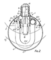
- a compact fluorescent lamp 1 having a chassis member 2, a lamp base member 3 and a globe member 4, is shown.
- the chassis member 2 is made of heat proof plastics (i.e. polycarbonate resin) and includes a cylindrical part 5 at one end thereof.
- the cylindrical part 5 consists of a plurality of screw thread portions 6 and a straight portion 7 which is formed to one end of the screw thread portions 6.
- the cylindrical part 5 is formed with opposing longitudinal recesses 9 and longitudinal slot 10 extending along the entire length of the outer surface thereof. Moreover, the top end of each of the recesses 9 and the slot 10 are open.
- the hemisphere shaped base member 3 having an upper opening 3a and a lower opening 3b, is attached to the cylindrical part 5 of the chassis member 2.
- the inside surface of the upper opening 3a is provided with opposing projection parts 12 and the attachment of the cylindrical part 5 to the base member 3 is accomplished by positioning the projections 12 of the base member 3 in the recesses 9 of the chassis,member 2.
- An incandescent lamp screw base 8 i.e. an E - 26 type base is fixed by screwing to the screw thread portions 6 of the cylindrical part 5.
- the base member 3 is provided with a plurality of arc-shaped openings 3' adjacent the lower peripheral opening 3b.
- the lower opening 3b of the base member 3 is mounted to the bowl shape globe member 4 which is made of plastics (i.e. polycarbonate) and colored, for example, white.
- the globe member 4 has a plurality of openings 4' to flow air near the top thereof.
- the connection of the base member 3 and the globe member 4 is achieved by cooperating hook portions 13 and 14 provided respectively at the peripheries of the base member 3 and globe member 4.
- two arm parts 15 are formed at one end on the cylindrical part 5 of the chassis member 2.
- a rectangular holding plate 16 is mounted to the top of the arm parts 15.
- a pair of opposed channel shaped fixing wall members 17 are respectively mounted in the holding plate 16 so as to face each other.
- ballast 18 is positioned and is fixed with its lead wires directed to the base member 3.
- a tube envelope 20 is mounted to the holding plate 16 so as to surround the ballast 18.
- the envelope 20 is made by bending a straight glass tube into a U-shape to form a first bent part 20a and a pair of first leg parts 20b, followed by the bending once more of each of the pair of leg parts 20b into second U-shapes to form second leg parts 20c and two pairs of second bent parts 20d.
- the thus formed envelope 20 is of a small and compact shape which may be referred to as a saddle shape envelope.
- the holding plate 16 of the chassis member 2 also provides a hook arm member 21 by way of a spreader plate 22 to hold the first bent part 20a of the envelope 20 and a maintaining plate 23 having parts 24 to hold both ends 20' of the winding envelope 20.
- the first bent part 20a of the envelope 20 is maintained between the hook arm member 21 and the spreader plate 22.
- the maintaining plate 23 is formed like a flange having semicircle pieces 24 at both ends thereof and the semicircle pieces 24 hold both ends 20' of the envelope 20.
- the holder plate 16 of the chassis member 2 provides a large heat shield plate 25 mounted to the maintaining plate 23 and a small heat shield plate 26 mounted to the spreader plate 22, so as to prevent radiant heat from being conducted directly to the first bent part 20a and the ends 20' of the envelope 20.
- Reference numerals 30 and 31 respectively refer to a glow starter and a condenser.
- the aforementioned ballast 18 is surrounded by the envelope 20; that is, the ballast 18 is positioned between the second bent parts 20d and the ends 20' of the winding envelope 20.
- the distance between the top of the ballast 18 and the ends 20' of the envelope 20 is about 10 mm and the distance between the bottom of the ballast 18 and the surface of the second bent parts 20d is about 7 mm.
- the distance between the top of the ballast 18 and the ends 20' of the winding envelope 20 is also about 10 mm and the interval between the bottom of the ballast 18 and the surface of the second bent parts 20d is also about 7 mm.
- the envelope 20 comes to have a coolest wall temperature portion regardless of the lighting direction.
- the mercury pressure in the envelope 20 is determined by the temperature of that coolest wall temperature of the envelope 20. That is, even if there is a portion having a higher temperature than the coolest wall temperature portion of the envelope 20, the mercury which is not vaporized in the envelope 20 condenses at the coolest wall temperature portion of the envelope 20. Consequently, the mercury pressure in the envelope 20 is prevented from increasing and is maintained at a desired value. A high luminous efficiency and a high output can thus be maintained regardless of the lighting directions.
- the lamp can be miniaturised by using a narrower spacing between the ballast 18 and envelope 20.
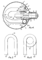
- the envelope may be of a U-shape having a bent part 51 and ends 52 as shown in Figure 5, or a spiral bent part 61 and ends 62, shown in Figure 6.
Applications Claiming Priority (2)
| Application Number | Priority Date | Filing Date | Title |
|---|---|---|---|
| JP103338/80 | 1980-07-28 | ||
| JP10333880A JPS5727557A (en) | 1980-07-28 | 1980-07-28 | Fluorescent lamp device |
Publications (2)
| Publication Number | Publication Date |
|---|---|
| EP0045182A1 true EP0045182A1 (de) | 1982-02-03 |
| EP0045182B1 EP0045182B1 (de) | 1985-10-23 |
Family
ID=14351357
Family Applications (1)
| Application Number | Title | Priority Date | Filing Date |
|---|---|---|---|
| EP81303368A Expired EP0045182B1 (de) | 1980-07-28 | 1981-07-23 | Kompakte Leuchtstofflampe |
Country Status (7)
| Country | Link |
|---|---|
| US (1) | US4417176A (de) |
| EP (1) | EP0045182B1 (de) |
| JP (1) | JPS5727557A (de) |
| KR (1) | KR830006815A (de) |
| AU (1) | AU531773B2 (de) |
| CA (1) | CA1180748A (de) |
| DE (1) | DE3172716D1 (de) |
Cited By (4)
| Publication number | Priority date | Publication date | Assignee | Title |
|---|---|---|---|---|
| GB2180988A (en) * | 1985-09-24 | 1987-04-08 | Linolite Ltd | A fluorescent lamp unit |
| GB2245417A (en) * | 1990-04-20 | 1992-01-02 | Koito Mfg Co Ltd | Discharge lamp. |
| US5220235A (en) * | 1990-04-20 | 1993-06-15 | Koito Manufacturing Co., Ltd. | Discharge lamp device |
| GB2317046A (en) * | 1996-09-04 | 1998-03-11 | Dieter Strueber | A discharge lamp |
Families Citing this family (8)
| Publication number | Priority date | Publication date | Assignee | Title |
|---|---|---|---|---|
| US4503360A (en) * | 1982-07-26 | 1985-03-05 | North American Philips Lighting Corporation | Compact fluorescent lamp unit having segregated air-cooling means |
| US5672932A (en) * | 1992-05-04 | 1997-09-30 | Goldman; Dennis | Compact lamp assembly with tubular portions arranged in V-shaped configuration |
| US5811937A (en) * | 1996-04-10 | 1998-09-22 | Link Usa International, Inc. | Bulb-type electronic energy-saving lamp |
| JP3324570B2 (ja) | 1999-06-16 | 2002-09-17 | 松下電器産業株式会社 | 電球形蛍光ランプ |
| JP2006302589A (ja) * | 2005-04-19 | 2006-11-02 | Osram-Melco Ltd | 電球形蛍光ランプ |
| US20070063656A1 (en) * | 2005-09-16 | 2007-03-22 | Istvan Wursching | Compact fluorescent lamp and method for manufacturing |
| US7804234B2 (en) * | 2007-07-10 | 2010-09-28 | General Electric Company | Self-ballasted compact fluorescent lamp and method for manufacturing |
| US20110115372A1 (en) * | 2009-11-17 | 2011-05-19 | General Electric Company | Electric lamp with pin connectors and method of manufacture |
Citations (3)
| Publication number | Priority date | Publication date | Assignee | Title |
|---|---|---|---|---|
| US3953761A (en) * | 1974-04-03 | 1976-04-27 | Thomas Lo Giudice | Fluorescent light bulb for use in conventional incandescent bulb fixture |
| GB2003314A (en) * | 1977-08-23 | 1979-03-07 | Philips Nv | Lamp unit |
| GB2033653A (en) * | 1978-10-26 | 1980-05-21 | Philips Nv | Low-pressure mercury vapour discharge lamp |
Family Cites Families (8)
| Publication number | Priority date | Publication date | Assignee | Title |
|---|---|---|---|---|
| NL179854C (nl) * | 1977-08-23 | 1986-11-17 | Philips Nv | Lagedrukkwikdampontladingslamp. |
| US4187446A (en) * | 1977-09-21 | 1980-02-05 | Leo Gross | Screw-in fluorescent lamp with magnetic arc spreading |
| US4300073A (en) * | 1979-02-13 | 1981-11-10 | Westinghouse Electric Corp. | Screw-in type lighting unit having a convoluted tridimensional fluorescent lamp |
| AU529323B2 (en) * | 1979-09-29 | 1983-06-02 | K.K. Toshiba | Fluorescent lamp |
| US4270071A (en) * | 1979-11-26 | 1981-05-26 | Westinghouse Electric Corp. | Composite base and ballast member for compact single-ended fluorescent lamp |
| US4347460A (en) * | 1980-03-03 | 1982-08-31 | Gte Products Corporation | Compact fluorescent lamp assembly |
| JPS5719959A (en) * | 1980-07-11 | 1982-02-02 | Toshiba Corp | Fluorescent lamp device |
| US4456854A (en) * | 1980-07-15 | 1984-06-26 | Tokyo Shibaura Denki Kabushiki Kaisha | Compact fluorescent lamp |
-
1980
- 1980-07-28 JP JP10333880A patent/JPS5727557A/ja active Pending
-
1981
- 1981-07-20 KR KR1019810002627A patent/KR830006815A/ko unknown
- 1981-07-22 US US06/285,731 patent/US4417176A/en not_active Expired - Fee Related
- 1981-07-23 DE DE8181303368T patent/DE3172716D1/de not_active Expired
- 1981-07-23 EP EP81303368A patent/EP0045182B1/de not_active Expired
- 1981-07-24 AU AU73456/81A patent/AU531773B2/en not_active Ceased
- 1981-07-28 CA CA000382675A patent/CA1180748A/en not_active Expired
Patent Citations (3)
| Publication number | Priority date | Publication date | Assignee | Title |
|---|---|---|---|---|
| US3953761A (en) * | 1974-04-03 | 1976-04-27 | Thomas Lo Giudice | Fluorescent light bulb for use in conventional incandescent bulb fixture |
| GB2003314A (en) * | 1977-08-23 | 1979-03-07 | Philips Nv | Lamp unit |
| GB2033653A (en) * | 1978-10-26 | 1980-05-21 | Philips Nv | Low-pressure mercury vapour discharge lamp |
Cited By (6)
| Publication number | Priority date | Publication date | Assignee | Title |
|---|---|---|---|---|
| GB2180988A (en) * | 1985-09-24 | 1987-04-08 | Linolite Ltd | A fluorescent lamp unit |
| GB2180988B (en) * | 1985-09-24 | 1990-04-04 | Linolite Ltd | A luminaire |
| GB2245417A (en) * | 1990-04-20 | 1992-01-02 | Koito Mfg Co Ltd | Discharge lamp. |
| US5220235A (en) * | 1990-04-20 | 1993-06-15 | Koito Manufacturing Co., Ltd. | Discharge lamp device |
| GB2245417B (en) * | 1990-04-20 | 1994-06-08 | Koito Mfg Co Ltd | Discharge lamp device |
| GB2317046A (en) * | 1996-09-04 | 1998-03-11 | Dieter Strueber | A discharge lamp |
Also Published As
| Publication number | Publication date |
|---|---|
| AU7345681A (en) | 1982-02-04 |
| EP0045182B1 (de) | 1985-10-23 |
| AU531773B2 (en) | 1983-09-08 |
| US4417176A (en) | 1983-11-22 |
| JPS5727557A (en) | 1982-02-13 |
| KR830006815A (ko) | 1983-10-06 |
| DE3172716D1 (en) | 1985-11-28 |
| CA1180748A (en) | 1985-01-08 |
Similar Documents
| Publication | Publication Date | Title |
|---|---|---|
| US4688874A (en) | Arrangement in electric discharge lamps | |
| US4449072A (en) | Compact fluorescent lamp | |
| US4417176A (en) | Compact fluorescent lamp | |
| JPS6021465B2 (ja) | 電気ランプ・ユニツト | |
| TW381292B (en) | Fluorescent lighting device and lighting apparatus | |
| US4456854A (en) | Compact fluorescent lamp | |
| US4794301A (en) | Fluorescent lamp having a convoluted discharge passage and fluorescent lamp apparatus incorporating the same | |
| GB2314965A (en) | Light-bulb-shaped fluorescent lamp | |
| US7012373B2 (en) | Electronic energy-saving fluorescent lamp of ultra-short chayote-shaped compact type | |
| US5445540A (en) | Attachment member for lamp socket and method | |
| US20100225218A1 (en) | Lighting Device | |
| JPS6016029Y2 (ja) | けい光ランプ装置 | |
| KR840002453B1 (ko) | 곡관형 형광램프 | |
| JPH0118538B2 (de) | ||
| KR850002265Y1 (ko) | 형광 램프 장치 | |
| JPS634331Y2 (de) | ||
| JPS6247169Y2 (de) | ||
| JPS5941566Y2 (ja) | けい光ランプ装置 | |
| JPS5819810Y2 (ja) | けい光ランプ装置 | |
| JPS5924122Y2 (ja) | けい光ランプ装置 | |
| CA1176300A (en) | Compact fluorescent lamp | |
| JPS6239537Y2 (de) | ||
| KR200265592Y1 (ko) | 전구식형광등 | |
| JPH08222183A (ja) | 電球形蛍光ランプ | |
| JPS60225348A (ja) | 螢光ランプ装置 |
Legal Events
| Date | Code | Title | Description |
|---|---|---|---|
| PUAI | Public reference made under article 153(3) epc to a published international application that has entered the european phase |
Free format text: ORIGINAL CODE: 0009012 |
|
| AK | Designated contracting states |
Designated state(s): DE FR GB IT NL |
|
| 17P | Request for examination filed |
Effective date: 19820715 |
|
| RAP1 | Party data changed (applicant data changed or rights of an application transferred) |
Owner name: KABUSHIKI KAISHA TOSHIBA |
|
| ITF | It: translation for a ep patent filed |
Owner name: STUDIO CONS. BREVETTUALE S.R.L. |
|
| GRAA | (expected) grant |
Free format text: ORIGINAL CODE: 0009210 |
|
| AK | Designated contracting states |
Designated state(s): DE FR GB IT NL |
|
| ET | Fr: translation filed | ||
| REF | Corresponds to: |
Ref document number: 3172716 Country of ref document: DE Date of ref document: 19851128 |
|
| PLBE | No opposition filed within time limit |
Free format text: ORIGINAL CODE: 0009261 |
|
| STAA | Information on the status of an ep patent application or granted ep patent |
Free format text: STATUS: NO OPPOSITION FILED WITHIN TIME LIMIT |
|
| 26N | No opposition filed | ||
| REG | Reference to a national code |
Ref country code: GB Ref legal event code: 746 |
|
| ITTA | It: last paid annual fee | ||
| PGFP | Annual fee paid to national office [announced via postgrant information from national office to epo] |
Ref country code: FR Payment date: 19920707 Year of fee payment: 12 |
|
| PGFP | Annual fee paid to national office [announced via postgrant information from national office to epo] |
Ref country code: GB Payment date: 19920713 Year of fee payment: 12 |
|
| PGFP | Annual fee paid to national office [announced via postgrant information from national office to epo] |
Ref country code: DE Payment date: 19920727 Year of fee payment: 12 |
|
| PGFP | Annual fee paid to national office [announced via postgrant information from national office to epo] |
Ref country code: NL Payment date: 19920731 Year of fee payment: 12 |
|
| PG25 | Lapsed in a contracting state [announced via postgrant information from national office to epo] |
Ref country code: GB Effective date: 19930723 |
|
| PG25 | Lapsed in a contracting state [announced via postgrant information from national office to epo] |
Ref country code: NL Effective date: 19940201 |
|
| NLV4 | Nl: lapsed or anulled due to non-payment of the annual fee | ||
| GBPC | Gb: european patent ceased through non-payment of renewal fee |
Effective date: 19930723 |
|
| PG25 | Lapsed in a contracting state [announced via postgrant information from national office to epo] |
Ref country code: FR Effective date: 19940331 |
|
| PG25 | Lapsed in a contracting state [announced via postgrant information from national office to epo] |
Ref country code: DE Effective date: 19940401 |
|
| REG | Reference to a national code |
Ref country code: FR Ref legal event code: ST |