EP0044505A1 - Harvester with a crop conveyor means - Google Patents
Harvester with a crop conveyor means Download PDFInfo
- Publication number
- EP0044505A1 EP0044505A1 EP81105488A EP81105488A EP0044505A1 EP 0044505 A1 EP0044505 A1 EP 0044505A1 EP 81105488 A EP81105488 A EP 81105488A EP 81105488 A EP81105488 A EP 81105488A EP 0044505 A1 EP0044505 A1 EP 0044505A1
- Authority
- EP
- European Patent Office
- Prior art keywords
- machine according
- harvesting machine
- bearing
- support
- bearing plate
- Prior art date
- Legal status (The legal status is an assumption and is not a legal conclusion. Google has not performed a legal analysis and makes no representation as to the accuracy of the status listed.)
- Granted
Links
Images


Classifications
-
- A—HUMAN NECESSITIES
- A01—AGRICULTURE; FORESTRY; ANIMAL HUSBANDRY; HUNTING; TRAPPING; FISHING
- A01D—HARVESTING; MOWING
- A01D61/00—Elevators or conveyors for binders or combines
- A01D61/008—Elevators or conveyors for binders or combines for longitudinal conveying, especially for combines
Definitions
- the invention relates to a harvesting machine with a harvesting device which has at least two cross conveyors, which are rotatably received on one end in the region of side walls of the harvesting device on the other end in the region of the mutually facing ends of the two cross conveyors by a bearing, which adapts to at least one extending above,. Support the carrying device connected to the harvesting device.
- a combine harvester is known (DE-AS 1 482 930), the mowing device of which has at least two adjacent parts which can be pivoted about at least one axis lying in the direction of travel, each with a cross conveyor, the cross conveyor in the region of the mutually facing ends of one extending upwards Carriers are included.
- the invention is based on the object of designing the carrying device and the mutually facing ends of two coaxially aligned transverse conveyors of a harvesting device in such a way that, in addition to simple, secure storage, rapid installation and removal of the transverse conveyors is possible.
- the inner bearing of a cross conveyor can be brought up to a traverse element of the carrying device and can be coupled thereto, transversely to the axis of the cross conveyor. Due to the advantageous design of the bearings for the mutually facing ends of the two cross conveyors, after mounting the outer ends of the cross conveyors on the side walls of the harvesting device, the inner bearings can be pivoted towards the carrying device and then easily connected to the end face of a single carrying device.
- the inner bearing has a bearing element which can be inserted laterally into the support element of the support device which is open at least on one side and is designed as a coupling element.
- the inner ends of the cross conveyors are equipped with shovel blades which adjoin screw spirals of the cross conveyor and extend radially and extend to the end face of the carrying device and which move the crop through an inlet opening. Due to the particularly favorable design of the bearing elements at the inner ends of the cross conveyor, the shovel blades provided on the screw core of the cross conveyor can be brought up to the region of the end face of the carrying device in order to ensure a uniform loading of the inlet opening.
- the carrying device is provided in the region of the inlet opening, to which a hood is assigned, which is connected in an articulated manner to a cross frame and extends forward and downward over the upper part of the inlet opening and the carrying device.
- the covering device can easily be pivoted upward, so that the installation and removal of the two cross conveyors is not hindered by the covering device and can therefore be carried out in the shortest possible time.
- the bearing elements each have a bearing plate with at least two guide surfaces and the support device has the coupling element with two contact surfaces, the coupling element forming a coupling pocket for the bearing plate in connection with the contact surfaces.
- the coupling element is equipped with two wings that run parallel to the guide surfaces and that are delimited by locking lips and by wings of the carrying device that run parallel to them. It is also advantageous that the locking lips with their wings and the wings of the support device form two guide grooves which run diverging from each other and limit the insertion movement of the bearing plate.
- the ends of the cross conveyors are automatically aligned by means of the guide surfaces of the coupling element, so that the cross conveyors are readily aligned with one another in the installed state.
- the carrying device is provided with a locking device for the bearing plate.
- the locking device is provided outside the outer circumference of a screw core of the cross conveyor.
- D a is the locking device or the associated bolt outside of the outer circumference of the screw core of the transverse conveyor is provided, the bolt can be readily on the carrier device mooring.
- the center line running through the two guide grooves forms an upwardly open, acute angle with a rear wall of the harvesting device and the bearing plate is adjustable on the same plane as the center line during the coupling process. Due to the advantageous position of the two converging grooves of the coupling device, the bearing plate of the corresponding cross conveyor can be easily inserted into the coupling element from the front and from above. It is advantageous that the cross conveyor is provided at its inner ends with a shaft journal which extends telescopically into the storage element. Since the shaft journal is axially displaceably received in the bearing element even in the installed state, bending and tensile stresses of the cross conveyor or its parts can be avoided in the event of tolerance deviations.
- an annular covering device which covers the inner ends of the screw core and has an upper removable part, which covers a mounting opening, is arranged on the carrying device. It is also advantageous that the upper part of the covering device for receiving the carrying device is provided at one end with a slot and an eyelet and at the other end with a hook part, the hook part being insertable into a receiving part provided on the lower part of the covering device.
- a rolling bearing is provided in the bearing plate, the outer ring of which is fixedly connected to the bearing plate, the bearing plate being able to be arranged between the end face of the cross conveyor and the end face of the carrying device.
- the support device consists of an upper, connected to the cross frame support arm and a lower vertical support plate which is adjustably mounted on the upper support arm in a vertical and horizontal plane and that the outer ends of the cross conveyor are detachably or insertably mounted in the side walls of the harvesting device by means of roller bearings.
- the use of adjusting means, which establish a connection between the vertically extending part and the forwardly inclined part of the carrying device, allows the mutually facing ends of the two cross conveyors to be aligned precisely with one another.
- the drawing shows a picking device for a harvesting machine, which can be equipped, for example, with 12 pickers arranged side by side (FIG. 1).
- the picking device 12 shown in the drawing can also be used for other machines, for example for swathers.
- the harvesting device is connected to a main frame 10 and equipped with numerous side-by-side picking devices 12, each of which has a feed channel 14 through which the crop is guided during harvesting, in order to then be caught by a feed screw 16 which connects to the end of the feed channel .
- the harvesting device with the individual picking devices 12 is connected to an inclined conveyor housing 18, which is only indicated in the drawing according to FIG. 1.
- the crop picked up by the auger 16 is drawn towards the center and fed to the inclined conveyor housing 18 via an inlet opening 20.
- the collection of the crop and the Delivery into the inclined conveyor housing 18 is supported by a cover device 22, which is located above the feed screw 16 and extends forwards from the inlet opening 20.
- the harvesting device has right and left side parts 24, in which the outer ends of the auger 16 are rotatably mounted.
- the rear part of the harvesting device is delimited by a rear wall 26.
- FIGS. 2 and 3 The details of the auger 16 are illustrated in FIGS. 2 and 3.
- the feed screw 16 is equipped with left and right screw feed parts 30 and 32, which act as cross conveyors, which cooperate with the bottom 34 and the rear wall 36 of the harvesting device.
- This also includes a squeegee 38, which is attached to the rear wall 36 and extends into the area of the rotation circle of the feed screw 16.
- the rear wall 36 and a cover device 22 are connected to a cross frame 40 and span the entire width of the harvesting device.
- Each screw feed part 30 and 32 has its outer ends supported in side walls 42 of the side parts 24 of the harvesting device.
- the inner ends of the screw feed parts 30 and 32 are received in a support device 44 which is arranged in the center with respect to the harvesting device and which is likewise firmly connected to the cross frame 40 (FIG. 1).
- the middle carrying device 44 is covered by means of the covering device 22, which consists of a panel 46 that slopes forward and downward and an approximately vertical panel 48 that is detachably connected to the front end of the panel 46.
- the front one Panel 48 extends with its lower edge into the region of the circle of rotation of screw feed parts 30 and 32.
- Upper and front panels 46 and 48 form a pivotable hood 47 which is connected to a fixed part 51 of covering device 22 by means of a joint 49 , so that the hood 47 can be pivoted into a position 47 'according to FIG. 3. During operation, the hood 47 is pivoted downwards and is secured by means of a fastening device 53.
- the screw feed part 30 has a screw core 50, which is equipped at the end with two adjacent end flanges 52, which each serve to receive an inner and outer hexagonal pin 54 and 56, which run coaxially with the screw core 50.
- Helical coils 58 are arranged on the worm core 50 and extend almost over the entire length of the worm core 50.
- the airfoils 60 support the loading of the inlet opening 20 with crop.
- the outer end of the pin 56 is received in a roller bearing 62 which is detachably connected to the side wall 42.
- a sprocket 64 for driving the screw feeder 30th
- the carrying device 44 which is arranged centrally with respect to the harvesting device, has an upper carrying part 70 which is firmly connected to the cross frame 40.
- the upper support part 70 is followed by an approximately vertical lower support part 72, to which a vertically extending support plate 82 (FIG. 2) belongs.
- a holder 76 and a holder 78 are located on the two outer surfaces of the support arm 74.
- a reinforcement plate 80 serves to stiffen the connection of the upper support arm 74 to the cross frame 40.
- the lower support part 72 of the support device 44 has the vertically extending support plate 82 with left and right support surfaces 84 and 86 extending in the longitudinal direction of the harvesting device.
- a bracket 88 is arranged on the left wing 84, which cooperates with a bracket 78 which is connected to the outside of the upper bracket 74.
- a horizontally extending adjusting bolt 90 is welded on the end face to the upper end of the support plate 82 and extends through an angular holder 76.
- the adjusting bolt 90 has nuts 94 on both sides of the web of the holder 76.
- the holder 88 is connected to the holder 78 via an adjusting bolt 92, the adjusting bolt being secured to the holder 78 by means of further nuts 94 on both sides of the holder.
- the fastening elements 96 can be designed as screw bolts which, after loosening, permit vertical and horizontal adjustment of the support plate 82 on the support arm 74, after the nuts 94 of the adjustment bolts 92 and 90 have also been loosened accordingly.
- each support element 102 is connected to the wings 84 and 86.
- Each support element 102 is arranged symmetrically with respect to a forward and upward sloping central plane 104.
- the central plane 104 extends through the center of the bore 100 and through two diametrically opposite connection bores 105 (FIG. 4).
- Each traq element 102 consists of a base 106 and a locking lip 108. The two support elements 102 converge in the direction of the base 34.
- the covering device 110 has two longitudinal slots 112 provided on both sides of the support plate 82 (FIG. 3).
- the inner end of the screw feed part 30 is rotatably and detachably received in a bearing which is designed as a roller bearing 120 and which includes a bearing plate 122 (FIG. 5), which is equipped with a bore 124 and a connection bore 126 and has two supporting edges or Guide surfaces 128 points, which are aligned symmetrically with respect to the center line extending through the bore 124 and the bore 126 and cooperate with the bottom 106 of the support element 102. If, for example, the rolling bearing 120 is pushed into the support elements 102, the corresponding support edges 128 run parallel to the floor 106, the central plane running through the bore 126 and the bore 124 running on the central plane 104. As can be seen from FIG.
- the bearing plate 122 has in the area of the bore 124 a bearing block 130 which is aligned coaxially to the bore 124 and which is connected via screw bolts 132 to the end face of the bearing plate 122 and which serves to receive the roller bearing 120 which is coaxial with the bearing block Bore 124 is aligned, the bearing block 130 lies at 133 against the surface of the support plate 122.
- a spacer bush 134 is provided on the pin 54 between the end flange. 52 and the end face of the roller bearing 120 in the bearing block 130, so that the bearing block 130 with the associated roller bearing, which may have a hexagonal hole, for example free end of the pin 54 can be pushed.
- a telescopic connection between the support plate 122 and the screw feed part 30 is established.
- the hood 47 is pivoted into a position according to 47', so that unhindered access to the screw feeder part 30, 32 is possible, in particular to the carrying device 44 32 is then slidably received in the side wall 42.
- the inner end of the screw feeder part becomes downwardly and rearwardly pivoted to the supporting edges 128 of the bearing plate 122 between the bottom 106 and the A RRE t istslippe 108 of the support members 102 can be pushed, and the connecting bore of the bearing plate 122 is aligned with the connecting bore 105 at the lower end of the Tragplätte 182,126.
- the surface of the bearing plate 122 then bears against the support surface 84 of the lower part of the support plate 82.
- axial adjustment of the bearing plate 122 with respect to the support plate 82 is limited in one direction. Axial adjustment of the bearing plate 122 is also prevented by the locking lip 108.
- the telescopic receiving of the hexagonal pin 54 in the rolling bearing 120 allows a certain adjustment of the screw feed part 30 in the axial direction so that manufacturing tolerances can be compensated for, so that the action of axial forces or thrust forces on the screw feed part 30 or the carrying device 44 can be prevented.
- the use of the spacer bush 134 ensures that the screw core 50 does not come into contact with the wing 84.
- the upper part 142 of the cover device 140 can be mounted.
- Der.Teil 142 is provided with a centrally aligned slot 144 in the rear area, which serves to receive the lower part of the support plate 82 and the upper part of the bearing plate 122.
- a hook-shaped connecting element 146 At the front lower end of the part 142 there is a hook-shaped connecting element 146, which is equipped with a tab or a hook part 148, which plugs into the slot 112 of the covering device 110 is cash.
- the upper part 142 of the cover device 140 has two eyelets 152 with longitudinal slots in the area of the end edge on both sides of the slot 144, which run coaxially to the bore 154 on the lower support plate 82 when the cover device 140 is installed.
- the upper part 140 acts with the lower part of the cover device 110 together, both parts forming an annular housing which coaxially surround the inner ends of the corresponding screw feed parts 30 and 32 and the associated bearing block 130.
- the screw bolt 56 can be screwed into the mutually aligned bores 126 and 105 of the bearing plate 122 and the support plate 82.
- the distance between the outer circumference of the screw spiral 58 and the surface of the bottom 34 and the end edge of the scraper strip 38 can be varied accordingly by means of the adjusting bolts 90 and 92. Since there is no direct connection between the adjoining screw feed parts 30 and 32, such an adjustment can be carried out in a simple manner without tensioning or damaging the individual screw feed parts.
- the airfoils 60 run close to the inner surface of the cover device 110 and 140, the relatively small axial space between the inner ends 158 of the airfoils 60 and the screw spirals 58 of the screw feed parts 30 and 32 ensure that a perfect Conveying effect of the two screw feed parts is ensured.
- the hood 47 needs to be raised and the outer roller bearing 62 in the side wall 42 has to be released.
- the bolts 156 can be removed and the upper part 142 of the cover device 140 can be removed, so that the inner end of the screw feeder part 30 or 32 can then be lifted first and then pulled up and out of the harvesting device.
Abstract
Die Erfindung bezieht sich auf eine Erntebergungsvorrichtung einer Erntebergungsmaschine mit zwei koaxial zueinander angeordneten Querförderern (30, 32) die an ihren inneren Enden je eine Lagerplatte (122) aufweisen, die in je ein an einer mittleren Tragvorrichtung (44) vorgesehenes Kupplungselement (102) von oben her einschiebbar sind, um auf diese Weise einen schnelleren Einbau bzw. Ausbau der Querförderer (30, 32) vorzunehmen. Die äußeren Enden der beiden Querförderer (30, 32) sind hierzu in den Seitenwänden (42) der Erntebergungsvorrichtung lösbar gelagert.The invention relates to a harvesting device of a harvesting machine with two transverse conveyors (30, 32) arranged coaxially to one another, each having a bearing plate (122) at their inner ends, each of which has a coupling element (102) provided on a central carrying device (44) can be pushed in from above in order to carry out a faster installation or removal of the cross conveyor (30, 32) in this way. For this purpose, the outer ends of the two cross conveyors (30, 32) are detachably mounted in the side walls (42) of the harvesting device.
Description
Die Erfindung bezieht sich auf eine Erntebergungsmaschine mit einer Erntebergungsvorrichtung, die mindestens zwei Querförderer aufweist, die einenends im Bereich von Seitenwänden der Erntebergungsvorrichtung anderenends im Bereich der einander zugewandten Enden der beiden Querförderer von je einem Lager drehbar aufgenommen sind, die sich an mindestens einer sich nach oben erstreckenden, . an der Erntebergungsvorrichtung angeschlossenen Tragvorrichtung abstützen.The invention relates to a harvesting machine with a harvesting device which has at least two cross conveyors, which are rotatably received on one end in the region of side walls of the harvesting device on the other end in the region of the mutually facing ends of the two cross conveyors by a bearing, which adapts to at least one extending above,. Support the carrying device connected to the harvesting device.
Es ist ein Mähdrescher bekannt (DE-AS 1 482 930), dessen Mähvorrichtung mindestens zwei nebeneinanderliegende um mindestens eine in Fahrtrichtung liegende Achse schwenkbare Teile mit je einem Querförderer aufweist, wobei die Querförderer im Bereich der einander zugewandten Enden von je einem sich nach oben erstreckenden Träger aufgenommen sind. Mit einer derartigen Vorrichtung lassen sich zwar relativ lange Querförderer lagern, da jedoch dem inneren Ende des entsprechenden Querförderers je ein Träger zuqeordnet ist, ist die Vorrichtung aufwendig und teuer. Außerdem ist der Ein- und Ausbau derartiger Querförderer kompliziert und zeitaufwendig.A combine harvester is known (DE-AS 1 482 930), the mowing device of which has at least two adjacent parts which can be pivoted about at least one axis lying in the direction of travel, each with a cross conveyor, the cross conveyor in the region of the mutually facing ends of one extending upwards Carriers are included. With such a device Although relatively long transverse conveyor can be stored, however, since the inner end of the corresponding transverse conveyor is eordnet depending on a carrier to q, the device is complicated and expensive. In addition, the installation and removal of such cross conveyors is complicated and time-consuming.
Ferner ist ein Querförderer für die Erntebergungsvorrichtung eines Mähdreschers bekannt (US-PS 3 977 164), der im mittleren Bereich über eine einzige Tragvorrichtung zusätzlich abgestützt ist, die an einen Querrahmen der Erntebergungsvorrichtung angeschlossen ist. Da die linken und rechten Teile des Querförderers mittig über Schraubenbolzen fest verbunden sind, läßt sich der Ein-und Ausbau eines einzelnen Teiles des Querförderers nicht ohne weiteres durchführen.Furthermore, a cross conveyor for the harvesting device of a combine harvester is known (US Pat. No. 3,977,164), which is additionally supported in the central region by means of a single carrying device which is connected to a cross frame of the harvesting device. Since the left and right parts of the cross conveyor are firmly connected in the center by means of bolts, the installation and removal of a single part of the cross conveyor can be done not perform easily.
Demgegenüber liegt der Erfindung die Aufgabe zugrunde, die Tragvorrichtung und die einander zugewandten Enden zweier koaxial zueinander ausgerichteter Querförderer einer Erntebergungsvorrichtung derart auszubilden, daß neben einer einfachen sicheren Lagerung ein schneller Ein- und Ausbau der Querförderer möglich ist..In contrast, the invention is based on the object of designing the carrying device and the mutually facing ends of two coaxially aligned transverse conveyors of a harvesting device in such a way that, in addition to simple, secure storage, rapid installation and removal of the transverse conveyors is possible.
Diese Aufgabe wird dadurch gelöst, daß jeweils das innenliegende Lager eines Querförderers quer zur Achse des Querförderers an ein Traqelement der Tragvorrichtung heranführbar und mit diesem kuppelbar ist. Durch die vorteilhafte Ausbildung der Lager für die einander zugewandten Enden der beiden Querförderer, lassen sich nach Montage der äußeren Enden der Querförderer an den Seitenwänden der Erntebergungsvorrichtung die inneren Lager an die Tragvorrichtung heranschwenken und dann mit der Stirnseite einer einzigen Tragvorrichtung ohne weiteres verbinden. Hierzu ist es vorteilhaft, daß das innenliegende Lager ein Lagerelement aufweist, das in das zumindest an einer Seite offene, als Kupplungselement ausgebildete Tragelement der Tragvorrichtung seitlich einschiebbar ist. Da die Tragvorrichtung mit einem nach einer Seite hin offenen Kupplungselement ausgerüstet ist, kann das Lagerelement auf einfache Weise seitlich in das Kupplungselement eingeschoben werden, bis das Lagerelement derart gegen das Kupplungselement anliegt, daß eine weitere Verstellung des Lagerelementes des entsprechenden Querförderers nicht mehr möglich ist. Hierdurch erhält man auf einfache Weise eine Arretierung des Lagerelementes in dem zugehörigen Kupplungselement, das mit der Tragvorrichtung verbunden ist. Hierzu ist es vorteilhaft, daß die koaxial zueinander verlaufenden und dicht nebeneinanderliegenden Lager an den innenliegenden Enden der Querförderer durch die einzige Traqvorrichtunq getrennt sind und auf Abstand gehalten werden. Da lediglich eine einzige Traqvorrichtunq zwischen den beiden einander qeqenüberlieqenden Enden der beiden Querförderer vorgesehen ist, erhält man bis in den Bereich der Tragvorrichtung eine einwandfreie Förderung des Erntegutes, so daß eine gute und gleichmäßige Beschickung der Einlaßöffnung mit Erntegut stets gewährleistet ist. Hierzu ist es vorteilhaft, daß die innenliegenden Enden der Querförderer mit sich an Schneckenwendeln des Querförderers anschließenden und sich radial erstreckenden, bis zur Stirnseite der Tragvorrichtung reichenden Schaufelblättern ausgerüstet sind, die das Erntegut durch eine Einlaßöffnung bewegen. Durch die besonders günstige Ausgestaltung der Lagerelemente an den innenliegenden Enden der Querförderer können die auf dem Schneckenkern des Querförderers vorgesehenen Schaufelblätter bis in den Bereich der Stirnseite der Tragvorrichtung herangeführt werden, um somit eine gleichmäßige Beschickung der Einlaßöffnung sicherzustellen.This object is achieved in that in each case the inner bearing of a cross conveyor can be brought up to a traverse element of the carrying device and can be coupled thereto, transversely to the axis of the cross conveyor. Due to the advantageous design of the bearings for the mutually facing ends of the two cross conveyors, after mounting the outer ends of the cross conveyors on the side walls of the harvesting device, the inner bearings can be pivoted towards the carrying device and then easily connected to the end face of a single carrying device. For this purpose, it is advantageous that the inner bearing has a bearing element which can be inserted laterally into the support element of the support device which is open at least on one side and is designed as a coupling element. Since the carrying device is equipped with a coupling element that is open on one side, the bearing element can easily be inserted laterally into the coupling element until the bearing element bears against the coupling element in such a way that a further adjustment of the bearing element of the corresponding cross conveyor is no longer possible. This provides a simple way of locking the bearing element in the associated coupling element which is connected to the carrying device. For this purpose, it is advantageous that the coaxial to each other ends and closely adjacent bearings at the inner ends of the cross conveyor are separated by the only traq device and are kept at a distance. Since only a single Traqvorrichtunq between the two ends qeqenüberlieqenden ends of the two cross conveyor is provided, you get a perfect conveyance of the crop up to the area of the carrying device, so that a good and uniform loading of the inlet opening with crop is always guaranteed. For this purpose, it is advantageous that the inner ends of the cross conveyors are equipped with shovel blades which adjoin screw spirals of the cross conveyor and extend radially and extend to the end face of the carrying device and which move the crop through an inlet opening. Due to the particularly favorable design of the bearing elements at the inner ends of the cross conveyor, the shovel blades provided on the screw core of the cross conveyor can be brought up to the region of the end face of the carrying device in order to ensure a uniform loading of the inlet opening.
Vorteilhaft ist es ferner, daß die Tragvorrichtung im Bereich der Einlaßöffnung vorgesehen ist, der eine Haube zugeordnet ist, die gelenkig an einem Querrahmen angeschlossen ist und sich nach vorne und unten über den oberen Teil der Einlaßöffnung und die Tragvorrichtung erstreckt. Um einen besseren Zugang zur Tragvorrichtung zu erhalten, läßt sich die Abdeckvorrichtung ohne weiteres nach oben verschwenken, so daß der Ein- und Ausbau der beiden Querförderer durch die Abdeckvorrichtung nicht behindert wird und sich somit in kürzester Zeit durchführen läßt.It is also advantageous that the carrying device is provided in the region of the inlet opening, to which a hood is assigned, which is connected in an articulated manner to a cross frame and extends forward and downward over the upper part of the inlet opening and the carrying device. In order to obtain better access to the carrying device, the covering device can easily be pivoted upward, so that the installation and removal of the two cross conveyors is not hindered by the covering device and can therefore be carried out in the shortest possible time.
Nach einem weiteren Merkmal der Erfindung ist es vorteilhaft, daß die Lagerelemente je eine Lagerplatte mit mindestens zwei Führungsflächen und die Tragvorrichtung das Kupplungselement mit zwei Anlageflächen aufweisen, wobei das Kupplungselement in Verbindung mit den Anlageflächen eine Kupplungstasche für die Lagerplatte bildet. Vorteilhaft ist es außerdem, daß das Kupplungselement mit zwei parallel zu den Führungsflächen verlaufenden Tragflächen ausgerüstet ist, die von Arretierungslippen und von parallel dazu verlaufenden Tragflächen der Tragvorrichtung begrenzt werden. Ferner ist es vorteilhaft, daß die Arretierungslippen mit ihren Tragflächen und den Tragflächen der Tragvorrichtung zwei Führungsnuten bilden, die divergierend zueinander verlaufen und die Einschubbewegung der Lagerplatte begrenzen. Durch die vorteilhafte Ausbildung des Kupplungselementes erhält man beim Einführen der Lagerplatte in das Kupplungselement gleichzeitig ein selbsttätiges Ausrichten der Enden der Querförderer mittels der Führungsflächen des Kupplungselementes, so daß die Querförderer im eingebauten Zustand ohne weiteres untereinander fluchten. Nachdem die Lagerplatte in das Kupplungselement eingeschoben ist, läßt sie sich auf einfache Weise sichern. Hierzu ist es vorteilhaft, daß die Tragvorrichtung mit einer Arretierungsvorrichtung für die Lagerplatte versehen ist. Es ist außerdem vorteilhaft, daß die Arretierungsvorrichtung außerhalb des Außenumfangs eines Schneckenkerns des Querförderers vorgesehen ist. Da die Arretierungsvorrichtung bzw. der zugehörige Schraubenbolzen außerhalb des Außenumfanges des Schneckenkerns des Querförderers vorgesehen ist, läßt sich der Schraubenbolzen ohne weiteres an der Tragvorrichtung festmachen.According to a further feature of the invention, it is advantageous that the bearing elements each have a bearing plate with at least two guide surfaces and the support device has the coupling element with two contact surfaces, the coupling element forming a coupling pocket for the bearing plate in connection with the contact surfaces. It is also advantageous that the coupling element is equipped with two wings that run parallel to the guide surfaces and that are delimited by locking lips and by wings of the carrying device that run parallel to them. It is also advantageous that the locking lips with their wings and the wings of the support device form two guide grooves which run diverging from each other and limit the insertion movement of the bearing plate. Due to the advantageous design of the coupling element, when the bearing plate is inserted into the coupling element, the ends of the cross conveyors are automatically aligned by means of the guide surfaces of the coupling element, so that the cross conveyors are readily aligned with one another in the installed state. After the bearing plate is inserted into the coupling element, it can be secured in a simple manner. For this purpose, it is advantageous that the carrying device is provided with a locking device for the bearing plate. It is also advantageous that the locking device is provided outside the outer circumference of a screw core of the cross conveyor. D a is the locking device or the associated bolt outside of the outer circumference of the screw core of the transverse conveyor is provided, the bolt can be readily on the carrier device mooring.
Nach einem anderen Merkmal der Erfindung ist es vorteilhaft, daß die durch die beiden Führungsnuten verlaufende Mittellinie mit einer Rückwand der Erntebergungsvorrichtung einen nach oben offenen, spitzen Winkel bildet und die Lagerplatte beim Kupplungsvorgang auf der gleichen Ebene wie die Mittellinie verstellbar ist. Durch die vorteilhafte Lage der beiden konvergierend zueinander angeordneten Nuten der Kupplungsvorrichtung läßt sich die Lagerplatte des entsprechenden Querförderers ohne weiteres von vorne und von oben in das Kupplungselement einschieben. Dabei ist es vorteilhaft, daß der Querförderer an seinen inneren Enden mit einem Wellenzapfen versehen ist, der sich teleskopartiq in das Laqerelement erstreckt. Da der Wellenzapfen auch im einqebauten Zustand axial verschiebbar in dem Laqerelement aufqenommen ist, können bei Toleranzabweichungen Biege- und Zugbeanspruchung des Querförderers bzw. von dessen Teilen vermieden werden.According to another feature of the invention, it is advantageous that the center line running through the two guide grooves forms an upwardly open, acute angle with a rear wall of the harvesting device and the bearing plate is adjustable on the same plane as the center line during the coupling process. Due to the advantageous position of the two converging grooves of the coupling device, the bearing plate of the corresponding cross conveyor can be easily inserted into the coupling element from the front and from above. It is advantageous that the cross conveyor is provided at its inner ends with a shaft journal which extends telescopically into the storage element. Since the shaft journal is axially displaceably received in the bearing element even in the installed state, bending and tensile stresses of the cross conveyor or its parts can be avoided in the event of tolerance deviations.
Nach einem weiteren Merkmal der Erfindung ist es vorteilhaft, daß an der Tragvorrichtung eine ringförmige, die inneren Enden des Schneckenkerns überdeckende Abdeckvorrichtung angeordnet ist, die einen oberen abnehmbaren Teil aufweist, die eine Montageöffnung abdeckt. Vorteilhaft ist es außerdem, daß der obere Teil der Abdeckvorrichtung zur Aufnahme der Tragvorrichtung einenends mit einem Schlitz sowie einer öse und anderenends mit einem Hakenteil versehen ist, wobei der Hakenteil in ein am unteren Teil der Abdeckvorrichtung vorgesehenes Aufnahmeteil einsteckbar ist.According to a further feature of the invention, it is advantageous that an annular covering device, which covers the inner ends of the screw core and has an upper removable part, which covers a mounting opening, is arranged on the carrying device. It is also advantageous that the upper part of the covering device for receiving the carrying device is provided at one end with a slot and an eyelet and at the other end with a hook part, the hook part being insertable into a receiving part provided on the lower part of the covering device.
Vorteilhaft ist es ferner, daß in der Lagerplatte ein Wälzlager vorgesehen ist, dessen Außenring fest mit der Lagerplatte verbunden ist, wobei die Lagerplatte zwischen der Stirnseite des Querförderers und der Stirnseite der Tragvorrichtung angeordnet werden kann.It is also advantageous that a rolling bearing is provided in the bearing plate, the outer ring of which is fixedly connected to the bearing plate, the bearing plate being able to be arranged between the end face of the cross conveyor and the end face of the carrying device.
Nach einem weiteren Merkmal der Erfindung ist es vorteilhaft, daß die Tragvorrichtung aus einem oberen, an den Querrahmen angeschlossenen Tragarm und einer unteren vertikalen Tragplatte besteht, die über Stellmittel in vertikaler und horizontaler Ebene am oberen Tragarm verstellbar gelagert ist und daß die äußeren Enden des Querförderers mittels Wälzlagern in den Seitenwänden der Erntebergungsvorrichtung lösbar bzw. einsteckbar gelagert sind. Durch die Verwendung von Stellmitteln, die eine Verbindung zwischen dem vertikalverlaufenden Teil und dem nach vorne geneigtverlaufenden Teil der Tragvorrichtung herstellen, lassen sich die einander zugewandten Enden der beiden Querförderer genau zueinander ausrichten.According to a further feature of the invention, it is advantageous that the support device consists of an upper, connected to the cross frame support arm and a lower vertical support plate which is adjustably mounted on the upper support arm in a vertical and horizontal plane and that the outer ends of the cross conveyor are detachably or insertably mounted in the side walls of the harvesting device by means of roller bearings. The use of adjusting means, which establish a connection between the vertically extending part and the forwardly inclined part of the carrying device, allows the mutually facing ends of the two cross conveyors to be aligned precisely with one another.
In der Zeichnung ist ein Ausführungsbeispiel einer Erntebergungsvorrichtung nach den Erfindung schematisch dargestellt.In the drawing, an embodiment of a harvesting device according to the invention is shown schematically.
Es zeigt:
- Fig. 1 eine Draufsicht einer Erntebergungsvorrichtung;
- Fig. 2 eine Teilansicht der Erntebergungsvorrichtung mit einer
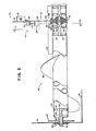
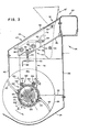
Einzugsschnecke 16; - Fig. 3 eine Teilansicht im Schnitt entlang der Linie 3-3 gemäß Fig. 2;
- Fig. 4 eine Teilansicht im Schnitt entlang der Linie 4-4 gemäß Fig. 3;
- Fig. 5 Teile des Lagers der Einzugsschnecke;
- Fig. 6 einen Längsschnitt entlang der Linie 6-6 gemäß Fig. 5;
- Fig. 7 den oberen Teil einer Abdeckvorrichtung für die Einzugsschnecke;
- Fig. 8 eine Draufsicht der Abdeckvorrichtung gemäß Fig. 7.
- 1 is a plan view of a harvesting device;
- Fig. 2 is a partial view of the harvesting device with an
auger 16; - FIG. 3 is a partial view in section along the line 3-3 according to FIG. 2;
- FIG. 4 is a partial view in section along the line 4-4 according to FIG. 3;
- Fig. 5 parts of the bearing of the auger;
- FIG. 6 shows a longitudinal section along the line 6-6 according to FIG. 5;
- 7 shows the upper part of a covering device for the feed screw;
- 8 is a plan view of the covering device according to FIG. 7.
In der Zeichnung ist eine.Pflückeinrichtung für eine Erntemaschine dargestellt, die beispielsweise mit 12 nebeneinander angeordneten Pflückern (Fig. 1) ausgerüstet sein kann. Die in der Zeichnung dargestellte Pflückeinrichtung 12 läßt sich jedoch auch für andere Maschinen beispielsweise für Schwadableger einsetzen.The drawing shows a picking device for a harvesting machine, which can be equipped, for example, with 12 pickers arranged side by side (FIG. 1). However, the
Die Erntebergungsvorrichtung ist an einen Hauptrahmen 10 angeschlossen und mit zahlreichen nebeneinander angeordneten Pflückeinrichtungen 12 ausgerüstet, die je einen Einzugskanal 14 aufweisen, durch den das Erntegut beim Ernteeinsatz geführt wird, um dann von einer Einzugsschnecke 16 erfaßt zu werden, die sich am Ende des Einzugskanals anschließt. Die Erntebergungsvorrichtung mit den einzelnen Pflückeinrichtungen 12 ist an ein Schrägfördergehäuse 18 angeschlossen, das in der Zeichnung gemäß Fig. 1 nur angedeutet ist. Das von der Einzugsschnecke 16 erfaßte Erntegut wird zur Mitte zusammengezogen und über eine Einlaßöffnung 20 dem Schrägfördergehäuse 18 zugeführt. Der Einzug des Erntegutes und die Abgabe in das Schrägfördergehäuse 18 wird durch eine Abdeckvorrichtung 22 unterstützt, die sich oberhalb der Einzugsschnecke 16 befindet und sich von der Einlaßöffnung 20 nach vorne erstreckt. Die Erntebergungsvorrichtung weist rechte und linke Seitenteile 24 auf, in denen die äußeren Enden der Einzugsschnecke 16 drehbar gelagert sind. Der hintere Teil der Erntebergungsvorrichtung wird durch eine Rückwand 26 begrenzt.The harvesting device is connected to a main frame 10 and equipped with numerous side-by-
Die Einzelheiten der Einzugsschnecke 16 sind in Fig. 2 und 3 veranschaulicht.The details of the
Die Einzugsschnecke 16 ist mit linken und rechten Schneckeneinzugsteilen 30 und 32, die als Querförderer wirken ausgerüstet, die mit dem Boden 34 und der Rückwand 36 der Erntebergungsvorrichtung zusammenwirken. Hierzu gehört auch eine Abstreifleiste 38, die an der Rückwand 36 befestigt ist und sich in den Bereich des Rotationskreises der Einzugsschnecke 16 erstreckt. Die Rückwand 36 sowie eine Abdeckvorrichtung 22 sind an einen Querrahmen 40 angeschlossen und überspannen die gesamte Breite der Erntebergungsvorrichtung. Ein jedes Schneckeneinzugsteil 30 und 32 lagert mit seinen äußeren Enden in Seitenwänden 42 der Seitenteile 24 der Erntebergungsvorrichtung.The
Die inneren Enden der Schneckeneinzugsteile 30 und 32 sind in einer mit Bezug auf die Erntebergungsvorrichtung mittig angeordneten Tragvorrichtung 44 aufgenommen, die ebenfalls mit dem Querrahmen 40 fest verbunden ist (Fig. 1). Die mittlere Tragvorrichtung 44 ist mittels der Abdeckvorrichtung 22 abgedeckt, die aus einem nach vorne und unten geneigtverlaufenden Paneel 46 und einem in etwa vertikalverlaufenden Paneel 48 besteht, das an das vordere Ende des Paneels 46 lösbar angeschlossen ist. Das vordere Paneel 48 erstreckt sich mit seiner unteren Kante bis in den Bereich des Rotationskreises der Schneckeneinzugsteile 30 und 32. Das obere und vordere Paneel 46 und 48 bilden eine schwenkbar gelagerte Haube 47, die mittels eines Gelenkes 49 an einen feststehenden Teil 51 der Abdeckvorrichtung 22 angeschlossen ist, so daß die Haube 47 in eine Stellung 47' gemäß Fig. 3 verschwenkt werden kann. Im Arbeitseinsatz ist die Haube 47 nach unten verschwenkt und wird mittels einer Befestigungsvorrichtung 53 gesichert.The inner ends of the
Da die Schneckeneinzugsteile 30 und 32 einander gleich sind, wird in der nachfolgenden Beschreibung lediglich das Schneckeneinzugsteil 30 näher beschrieben und in Fig. 2 veranschaulicht. Das Schneckeneinzugsteil 30 weist einen Schneckenkern 50 auf, der endseitig mit zwei nebeneinanderliegenden Stirnflanschen 52 ausgerüstet ist, die jeweils zur Aufnahme eines inneren und äußeren sechskantförmigen Zapfens 54 und 56 dienen, die koaxial zum Schneckenkern 50 verlaufen. Auf dem Schneckenkern 50 sind Schneckenwendeln 58 angeordnet, die sich fast über die gesamte Länge des Schneckenkerns 50 erstrecken. Am inneren Ende der Schneckenwendel 58 schließt sich ein kurzes Schaufelblatt 60 an, das sich bis in den Bereich der Stirnseite der Tragvorrichtung 44 erstreckt. Wie insbesondere aus Fig. 2 und Fig. 3 hervorgeht sind lediglich zwei Schaufelblätter 60 dargestellt, die gegenüberliegend angeordnet sind. Es ist jedoch auch möglich, mehrere Schaufelblätter am Schneckenkern 50 anzuschließen. Die Schaufelblätter 60 unterstützen die Beschickung der Einlaßöffnung 20 mit Erntegut. Das äußere Ende des Zapfens 56 ist in einem Wälzlager 62 aufgenommen, das an die Seitenwand 42 lösbar angeschlossen ist. Zwischen der außenliegenden Stirnseite des Schneckeneinzugsteils 30 und der Seitenwand 42 befindet sich ein Kettenrad 64 zum Antrieb des Schneckeneinzugsteiles 30.Since the
Die mit Bezug auf die Erntebergungsvorrichtung mittig angeordnete Tragvorrichtung 44 weist ein oberes Tragteil 70 auf, das an dem Querrahmen 40 fest angeschlossen ist. An dem oberen Tragteil 70 schließt sich ein in etwa vertikalverlaufendes unteres Tragteil 72 an, zu dem eine vertikalverlaufende Tragplatte 82 (Fig. 2) gehört. An den beiden außenliegenden Oberflächen des Tragarmes 74 befindet sich eine Halterung 76 sowie eine Halterung 78. Eine Verstärkerplatte 80 dient zur Versteifung der Verbindung des oberen Tragarmes 74 mit dem Querrahmen 40.The carrying
Das untere Tragteil 72 der Tragvorrichtung 44 weist die vertikalverlaufende Tragplatte 82 mit linken und rechten sich in Längsrichtung der Erntebergungsvorrichtung erstreckenden Tragflächen 84 und 86 auf. An die linke Tragfläche 84 ist eine Halterung 88 angeordnet, die mit einer Halterung 78 zusammenwirkt, die an der Außenseite des oberen Tragarmes 74 angeschlossen ist. Ein horizontalverlaufender Einstellbolzen 90 ist an das obere Ende der Tragplatte 82 stirnseitig angeschweißt und erstreckt sich durch eine winkelförmige Halterung 76. Der Stellbolzen 90 weist beiderseits des Steges der Halterung 76 Muttern 94 auf. Die Halterung 88 ist über einen Einstellbolzen 92 mit der Halterung 78 verbunden, wobei der Einstellbolzen an der Halterung 78 mittels weiterer Muttern 94 beiderseits der Halterung gesichert ist. Mittels der Einstellbolzen 90 und 92 ist eine vertikale und eine horizontale Verstellung der Tragplatte 82 am Tragarm 74 möglich. Am vorderen unteren Ende des Tragarmes 74 sowie an dem oberen Ende der Tragplatte 82 befinden sich zwei untereinander fluchtende Schlitzführungen 98 durch die sich Befestigungselemente 96 erstrecken. Die Befestigungselemente 96 können als Schraubenbolzen ausgebildet sein, die nach Lösen eine Vertikal- sowie eine Horizontalverstellung der Tragplatte 82 am Tragarm 74 gestattet, nachdem hierzu auch die Muttern 94 der Einstellbolzen 92 und 90 entsprechend gelöst worden sind.The
Am unteren Ende der Tragplatte 82 befindet sich eine Bohrung 100 (Fig. 4), die von zwei gegenüberliegenden Tragelementen 102 flankiert wird. Die beiden Tragelemente 102 sind an den Tragflächen 84 und 86 angeschlossen. Ein jedes Tragelement 102 ist mit Bezug auf eine nach vorne und oben schrägverlaufende Mittelebene 104 symetrisch angeordnet. Die Mittelebene 104 erstreckt sich durch den Mittelpunkt der Bohrunq 100 und durch zwei diametral gegenüberliegende Anschlußbohrungen 105 (Fig. 4). Ein jedes Traqelement 102 besteht aus einem Boden 106 sowie aus einer Arretierungslippe 108. Die beiden Tragelemente 102 laufen in Richtung des Bodens 34 zusammen.At the lower end of the
Am unteren Ende der Tragplatte 82 befindet sich konzentrisch zur Bohrunq 100 eine halbkreisförmige Abdeckvorrichtung 110, die mit Bezuq auf die Mittelebene 104 svmetrisch ausgerichtet ist und die sich beiderseits axial zu den Traqflächen 84 und 86 der Traqplatte 82 erstreckt. Die Abdeckvorrichtung 110 weist zwei beiderseits der Tragplatte 82 vorgesehene Längsschlitze 112 auf (Fig. 3).At the lower end of the
Das innere Ende des Schneckeneinzugsteils 30 ist drehbar und lösbar in einem Lager, das als Wälzlager 120 ausgebildet ist und zu dem eine Lagerplatte 122 (Fig. 5) gehört, aufgenommen, die mit einer Bohrung 124 und einer Anschlußbohrung 126 ausgerüstet ist und zwei Tragkanten bzw. Führungsflächen 128 aufweist, die mit Bezug auf die durch die Bohrung 124 und die Bohrung 126 verlaufende Mittellinie symetrisch ausgerichtet sind und mit dem Boden 106 des Tragelementes 102 zusammenwirken. Wird also beispielsweise das Wälzlager 120 in die Tragelemente 102 eingeschoben, so verlaufen die entsprechenden Tragkanten 128 parallel zum Boden 106, wobei die durch die Bohrung 126 und die Bohrung 124 verlaufende Mittelebene auf der Mittelebene 104 verläuft. Wie aus Fig. 6 hervorgeht, weist die Lagerplatte 122 im Bereich der Bohrung 124 einen koaxial zur Bohrung 124 ausgerichteten Lagerbock 130 auf, der über Schraubenbolzen 132 mit der Stirnfläche der Lagerplatte 122 verbunden ist und der zur Aufnahme des Wälzlagers 120 dient, das koaxial zur Bohrung 124 ausgerichtet ist, dabei liegt der Lagerbock 130 bei 133 gegen die Oberfläche der Tragplatte 122 an.The inner end of the
Wie aus Fig. 2 hervorgeht, ist auf dem Zapfen 54 zwischen dem Stirnflansch.52 und der Stirnseite des Wälzlagers 120 im Lagerbock 130 eine Distanzbuchse 134 vorgesehen, so daß der Lagerbock 130 mit dem zugehörigen Wälzlager, das beispielsweise eine Sechskantbohrung aufweisen kann, auf das freie Ende des Zapfens 54 aufgeschoben werden kann. Auf diese Weise wird eine teleskopartige Verbindung zwischen der Tragplatte 122 und dem Schneckeneinzugsteil 30 hergestellt. Bevor jedoch das Schneckeneinzugsteil 30 in der Erntebergungsvorrichtung'eingebaut werden kann, wird die Haube 47 in eine Stellung gemäß 47' verschwenkt, so daß ein ungehinderter Zugang zum Schneckeneinzugsteil 30, 32 möglich ist, insbesondere zur Tragvorrichtung 44. Das äußere Ende des Schneckeneinzugsteiles 30 bzw. 32 wird dann in der Seitenwand 42 verschiebbar aufgenommen. Danach wird das innere Ende des Schneckeneinzugsteils nach unten und hinten verschwenkt bis die Tragkanten 128 der Lagerplatte 122 zwischen den Boden 106 und die Arre- tierungslippe 108 der Tragelemente 102 geschoben werden können und die Anschlußbohrung 126 der Lagerplatte 122 mit der Anschlußbohrung 105 am unteren Ende der Tragplätte 182 fluchtet. Im eingebauten Zustand liegt dann die Oberfläche der Lagerplatte 122 gegen die Tragfläche 84 des unteren Teils der Tragplatte 82 an. Wenn die Tragkanten 128 gegen die Böden 106 anlieqen, ist eine Axialverstellung der Lagerplatte 122 mit Bezug auf die Tragplatte 82 in eine Richtung begrenzt. Durch die Arretierungslippe 108 wird auch eine Axialverstellung der Lagerplatte 122 verhindert.As can be seen from FIG. 2, a
Die teleskopartige Aufnahme des sechskantförmigen Zapfens 54 im Wälzlager 120 ermöglicht eine bestimmte Verstellung des Schneckeneinzugsteiles 30 in Axialrichtung um somit Fertigungstoleranzen ausgleichen zu können, so daß hierdurch die Einwirkung von Axialkräften oder Schubkräften auf das Schneckeneinzugsteil 30 oder die Tragvorrichtung 44 verhindert werden kann. Durch die Verwendung der Distanzbuchse 134 wird sichergestellt, daß der Schneckenkern 50 nicht gegen die Tragfläche 84 zur Anlage kommt.The telescopic receiving of the
Wenn beide Schneckeneinzugsteile 30 und 32 auf diese Weise eingebaut sind, kann der obere Teil 142 der Abdeckvorrichtung 140 montiert werden. Der.Teil 142 ist mit einem mittig ausgerichteten Schlitz 144 im hinteren Bereich versehen, der zur Aufnahme des unteren Teils der Tragplatte 82 und des oberen Teils der Lagerplatte 122 dient. An dem vorderen unteren Ende des Teils 142 befindet sich ein hakenförmiges Anschlußelement 146, das mit einer Lasche bzw. einem Hakenteil 148 ausgerüstet ist, der in den Schlitz 112 der Abdeckvorrichtung 110 einsteckbar ist. Das obere Teil 142 der Abdeckvorrichtung 140 weist im Bereich der Stirnkante beiderseits des Schlitzes 144 zwei ösen 152 mit Längsschlitzen auf, die im eingebauten Zustand der Abdeckvorrichtung 140 koaxial zur Bohrung 154 an der unteren Tragplatte 82 verlaufen Im eingebauten Zustand wirkt das obere Teil 140 mit dem unteren Teil der Abdeckvorrichtung 110 zusammen, wobei beide Teile ein ringförmiges Gehäuse bilden, das die inneren Enden der entsprechenden Schneckeneinzugsteile 30 und 32 und den zugehörigen Lagerbock 130 koaxial umaeben. Wenn die Schneckeneinzuqsteile 30 und 32 eingebaut sind, kann der Schraubenbolzen 56 in die untereinander fluchtenden Bohrunqen 126 und 105 der Lagerplatte 122 und der Tragplatte 82 eingeschraubt werden. Der Abstand zwischen dem Außenumfang der Schneckenwendel 58 und der Oberfläche des Bodens 34 sowie der Stirnkante der Abstreifleiste 38, kann mittels der Einstellbolzen 90 und 92 entsprechend variiert werden. Da keine direkte Verbindung zwischen den aneinander angrenzenden Schneckeneinzugsteilen 30 und 32 besteht, kann eine derartige Einstellung auf einfache Weise durchgeführt werden, ohne dabei die einzelnen Schneckeneinzugsteile zu verspannen bzw. zu beschädigen.When both screw
Wie aus Fig. 2 hervorgeht, laufen die Schaufelblätter 60 dicht an der Innenoberfläche der Abdeckvorrichtung 110 und 140 vorbei, wobei der relativ kleine axiale Raum zwischen den inneren Enden 158 der Schaufelblätter 60 und den Schneckenwendeln 58 der Schneckeneinzugsteile 30 und 32 gewährleisten, daß eine einwandfreie Förderwirkung der beiden Schneckeneinzugsteile sichergestellt ist. Um eines der beiden Schneckeneinzugsteile 30 bzw. 32 auszubauen, braucht lediglich die Haube 47 angehoben zu werden und das äussere Wälzlager 62 in der Seitenwand 42 gelöst zu werden. Danach lassen sich die Schraubenbolzen 156 entfernen und der obere Teil 142 der Abdeckvorrichtung 140 abnehmen, so daß dann das innere Ende des Schneckeneinzugsteils 30 bzw. 32 zuerst angehoben werden kann, um dann nach oben und vorne aus der Erntebergungsvorrichtung herausgezogen zu werden.As is apparent from Fig. 2, the
Claims (17)
Applications Claiming Priority (2)
| Application Number | Priority Date | Filing Date | Title |
|---|---|---|---|
| US06/170,263 US4300333A (en) | 1980-07-18 | 1980-07-18 | Auger conveyor for a crop harvester |
| US170263 | 1980-07-18 |
Publications (2)
| Publication Number | Publication Date |
|---|---|
| EP0044505A1 true EP0044505A1 (en) | 1982-01-27 |
| EP0044505B1 EP0044505B1 (en) | 1985-04-10 |
Family
ID=22619202
Family Applications (1)
| Application Number | Title | Priority Date | Filing Date |
|---|---|---|---|
| EP81105488A Expired EP0044505B1 (en) | 1980-07-18 | 1981-07-14 | Harvester with a crop conveyor means |
Country Status (8)
| Country | Link |
|---|---|
| US (1) | US4300333A (en) |
| EP (1) | EP0044505B1 (en) |
| AR (1) | AR231482A1 (en) |
| AU (1) | AU535872B2 (en) |
| BR (1) | BR8104537A (en) |
| CA (1) | CA1145561A (en) |
| DE (1) | DE3169816D1 (en) |
| ES (1) | ES504055A0 (en) |
Families Citing this family (19)
| Publication number | Priority date | Publication date | Assignee | Title |
|---|---|---|---|---|
| US4344442A (en) * | 1981-04-24 | 1982-08-17 | Sperry Corporation | Anti-wrap apparatus |
| US4669945A (en) * | 1986-03-26 | 1987-06-02 | J. I. Case Company | Foldable and swivelable hopper-loading screw conveyor |
| DE4021030C2 (en) * | 1990-07-03 | 1994-10-06 | Gustav Schumacher | Mowing table for harvesting machines |
| US5673543A (en) * | 1996-01-04 | 1997-10-07 | Byron Enterprises, Inc | Foldable corn head with unobstructed auger |
| CA2334409A1 (en) | 2000-02-08 | 2001-08-08 | United States Filter Corporation | Grit washer and bearing assembly therefore |
| US6564535B1 (en) * | 2000-03-07 | 2003-05-20 | Agco Corporation | Drive mechanism for center gathering double augers of a crop harvester |
| US6877303B2 (en) * | 2002-07-19 | 2005-04-12 | Cnh America Llc | Stub auger support used in pickup |
| US20080256920A1 (en) * | 2006-10-20 | 2008-10-23 | Aaron Yanke | Mower Conditioner Having Auger Flights Positioned Over a Cutter Bar to Effect Clearing Thereof |
| US7614206B2 (en) * | 2007-06-04 | 2009-11-10 | Claas Selbstfahrende Erntemaschinen Gmbh | Winged header apparatus and method for a combine |
| US7587885B2 (en) * | 2007-06-04 | 2009-09-15 | Claas Selbstfahrende Emtemaschinen Gmbh | Central auger crop feed system for a harvester |
| US7562879B1 (en) | 2008-04-30 | 2009-07-21 | Cnh America Llc | Method and apparatus for creating an auger arm and bearing seal |
| US20100212277A1 (en) * | 2009-02-20 | 2010-08-26 | Marrs William R | Crop harvester |
| US8635842B2 (en) | 2009-08-05 | 2014-01-28 | Kevin Markt | Flexible row crop header for an agricultural harvester |
| BE1021143B1 (en) * | 2013-05-06 | 2016-01-18 | Cnh Industrial Belgium Nv | UNIT FOR A HARVESTER WITH REMOVABLE EXTENSION PLATES |
| US9456548B2 (en) * | 2014-02-14 | 2016-10-04 | Deere & Company | Conveyer for a material processing machine |
| US9814181B2 (en) * | 2015-05-08 | 2017-11-14 | Cnh Industrial America Llc | Drive mechanism for augers of an agricultural harvester header |
| US10653061B2 (en) | 2015-07-07 | 2020-05-19 | Deere & Company | Method and apparatus for harvesting crop material |
| US10820509B2 (en) * | 2017-08-08 | 2020-11-03 | Cnh Industrial America Llc | Foldable corn head |
| US11758850B2 (en) * | 2019-09-30 | 2023-09-19 | Deere & Company | Combine header with split augers and method of using the same |
Citations (9)
| Publication number | Priority date | Publication date | Assignee | Title |
|---|---|---|---|---|
| US1733839A (en) * | 1925-12-16 | 1929-10-29 | H V Mckay Proprietary Ltd | Reaper thrasher and like harvesting machine |
| US2390680A (en) * | 1944-04-10 | 1945-12-11 | Harry S Ausherman | Feeding mechanism for threshing combines |
| US2476265A (en) * | 1946-09-25 | 1949-07-12 | Vaughn H Doyle | Auger conveyer unit for harvesters |
| FR1267842A (en) * | 1960-06-13 | 1961-07-28 | Advanced intermediate bearing for conveyor screws and propellers | |
| US3144282A (en) * | 1961-04-03 | 1964-08-11 | Galion Jeffrey Mfg Co | Air purged bearing for sprial conveyor |
| FR1518696A (en) * | 1965-11-30 | 1968-03-29 | Blanch Lely Ltd | Harvesting machine |
| FR1577198A (en) * | 1967-08-31 | 1969-08-01 | ||
| DE1482930A1 (en) * | 1964-11-27 | 1969-11-20 | Texas Industries Inc | Harvester |
| US3977164A (en) * | 1975-04-10 | 1976-08-31 | Massey-Ferguson Industries Limited | Center support for combine table auger |
Family Cites Families (9)
| Publication number | Priority date | Publication date | Assignee | Title |
|---|---|---|---|---|
| CA538449A (en) * | 1957-03-19 | Ashton Robert | Harvesting mechanism | |
| DE306126C (en) * | ||||
| US3072243A (en) * | 1959-06-09 | 1963-01-08 | Link Belt Co | Screw conveyor coupling |
| US3112593A (en) * | 1961-01-30 | 1963-12-03 | Jacob A Ronning | Rotary lawn tool |
| US3324639A (en) * | 1964-07-23 | 1967-06-13 | Sperry Rand Corp | Auger header and crop conditioner |
| US3327840A (en) * | 1965-07-21 | 1967-06-27 | Deere & Co | Adjustable livestock feeder |
| DE2208498A1 (en) * | 1972-02-23 | 1973-09-13 | Deere & Co | DRIVE ARRANGEMENT FOR THE RETURNING KNIFE OF THE HEADING DEVICE AND THE INFEED ROLLER OF COMBINE HARVESTERS |
| FI53198C (en) * | 1976-01-13 | 1978-03-10 | Paraisten Kalkki Oy | |
| US4216641A (en) * | 1979-06-13 | 1980-08-12 | Sperry Corporation | Crop harvesting machine |
-
1980
- 1980-07-18 US US06/170,263 patent/US4300333A/en not_active Expired - Lifetime
-
1981
- 1981-06-17 CA CA000379976A patent/CA1145561A/en not_active Expired
- 1981-07-02 AU AU72491/81A patent/AU535872B2/en not_active Ceased
- 1981-07-14 EP EP81105488A patent/EP0044505B1/en not_active Expired
- 1981-07-14 DE DE8181105488T patent/DE3169816D1/en not_active Expired
- 1981-07-15 BR BR8104537A patent/BR8104537A/en unknown
- 1981-07-17 AR AR286138A patent/AR231482A1/en active
- 1981-07-17 ES ES504055A patent/ES504055A0/en active Granted
Patent Citations (9)
| Publication number | Priority date | Publication date | Assignee | Title |
|---|---|---|---|---|
| US1733839A (en) * | 1925-12-16 | 1929-10-29 | H V Mckay Proprietary Ltd | Reaper thrasher and like harvesting machine |
| US2390680A (en) * | 1944-04-10 | 1945-12-11 | Harry S Ausherman | Feeding mechanism for threshing combines |
| US2476265A (en) * | 1946-09-25 | 1949-07-12 | Vaughn H Doyle | Auger conveyer unit for harvesters |
| FR1267842A (en) * | 1960-06-13 | 1961-07-28 | Advanced intermediate bearing for conveyor screws and propellers | |
| US3144282A (en) * | 1961-04-03 | 1964-08-11 | Galion Jeffrey Mfg Co | Air purged bearing for sprial conveyor |
| DE1482930A1 (en) * | 1964-11-27 | 1969-11-20 | Texas Industries Inc | Harvester |
| FR1518696A (en) * | 1965-11-30 | 1968-03-29 | Blanch Lely Ltd | Harvesting machine |
| FR1577198A (en) * | 1967-08-31 | 1969-08-01 | ||
| US3977164A (en) * | 1975-04-10 | 1976-08-31 | Massey-Ferguson Industries Limited | Center support for combine table auger |
Also Published As
| Publication number | Publication date |
|---|---|
| ES8204578A1 (en) | 1982-05-16 |
| EP0044505B1 (en) | 1985-04-10 |
| US4300333A (en) | 1981-11-17 |
| BR8104537A (en) | 1982-03-30 |
| AU7249181A (en) | 1982-01-21 |
| CA1145561A (en) | 1983-05-03 |
| DE3169816D1 (en) | 1985-05-15 |
| AU535872B2 (en) | 1984-04-05 |
| ES504055A0 (en) | 1982-05-16 |
| AR231482A1 (en) | 1984-12-28 |
Similar Documents
| Publication | Publication Date | Title |
|---|---|---|
| EP0044505B1 (en) | Harvester with a crop conveyor means | |
| DE2556688C2 (en) | Device for picking up and conveying crops, in particular grain, on a harvesting machine, in particular a combine harvester | |
| DE2834729C3 (en) | Combine grain tank | |
| DE2728162A1 (en) | GRAIN TANK EMPTYING DEVICE FOR COMBINE | |
| DE19632895C2 (en) | Harvester | |
| DE1482929A1 (en) | Harvesting machine, especially a combine harvester | |
| DE2736005A1 (en) | IN-LINE ATTACHMENT FOR FIELD HARVESTERS | |
| DE2248446A1 (en) | HARVESTER | |
| DE1507391B2 (en) | Rotary haymaker | |
| DE3522699C2 (en) | Self-propelled harvester | |
| DE102011118791B4 (en) | Conveyor belt for use in a milling device and milling device with such a conveyor belt | |
| DE1582454A1 (en) | Loading wagons | |
| DE2712991A1 (en) | AGRICULTURAL MACHINE WITH CONVERTIBLE PICKUP DEVICE | |
| DE102011008723A1 (en) | Harvest header for a harvester | |
| EP0014854A1 (en) | Collecting device for a forage harvester | |
| DE2345494A1 (en) | COLLECTOR PLATE ARRANGEMENT IN A PISTON PICK ADD-ON DEVICE | |
| DE2530105A1 (en) | SOIL TILLING MACHINE | |
| DE3422426A1 (en) | AGRICULTURAL MACHINE FOR TRANSFERRING HARVESTED GROUND | |
| DE102007053568A1 (en) | Harvester, particularly trailer with loading facility and bailing press, has receiving device for receiving product harvested from earth and cross conveyor, which has cross conveyor rollers assigned to lateral edge areas of receiving rotor | |
| DE2419909C2 (en) | Transfer stand for continuous conveyors such as belt conveyors or the like | |
| EP0105055A1 (en) | Lorry for receiving a harvesting device | |
| DE2924732A1 (en) | TILLAGE MACHINE | |
| DE2425087C2 (en) | Agricultural loading vehicle | |
| DE1806666A1 (en) | Agricultural machine, in particular mowing machine | |
| DE1482177C3 (en) | Haymaking machine |
Legal Events
| Date | Code | Title | Description |
|---|---|---|---|
| PUAI | Public reference made under article 153(3) epc to a published international application that has entered the european phase |
Free format text: ORIGINAL CODE: 0009012 |
|
| AK | Designated contracting states |
Designated state(s): DE FR IT |
|
| ITCL | It: translation for ep claims filed |
Representative=s name: LENZI & C. |
|
| 17P | Request for examination filed |
Effective date: 19820717 |
|
| ITF | It: translation for a ep patent filed |
Owner name: LENZI & C. |
|
| GRAA | (expected) grant |
Free format text: ORIGINAL CODE: 0009210 |
|
| AK | Designated contracting states |
Designated state(s): DE FR IT |
|
| REF | Corresponds to: |
Ref document number: 3169816 Country of ref document: DE Date of ref document: 19850515 |
|
| ET | Fr: translation filed | ||
| PLBE | No opposition filed within time limit |
Free format text: ORIGINAL CODE: 0009261 |
|
| STAA | Information on the status of an ep patent application or granted ep patent |
Free format text: STATUS: NO OPPOSITION FILED WITHIN TIME LIMIT |
|
| 26N | No opposition filed | ||
| PG25 | Lapsed in a contracting state [announced via postgrant information from national office to epo] |
Ref country code: FR Free format text: LAPSE BECAUSE OF NON-PAYMENT OF DUE FEES Effective date: 19880331 |
|
| PG25 | Lapsed in a contracting state [announced via postgrant information from national office to epo] |
Ref country code: DE Effective date: 19880401 |
|
| REG | Reference to a national code |
Ref country code: FR Ref legal event code: ST |