EP0043723B1 - Enregistrement continu d'une bande - Google Patents
Enregistrement continu d'une bande Download PDFInfo
- Publication number
- EP0043723B1 EP0043723B1 EP81303068A EP81303068A EP0043723B1 EP 0043723 B1 EP0043723 B1 EP 0043723B1 EP 81303068 A EP81303068 A EP 81303068A EP 81303068 A EP81303068 A EP 81303068A EP 0043723 B1 EP0043723 B1 EP 0043723B1
- Authority
- EP
- European Patent Office
- Prior art keywords
- web
- radiation
- locating portions
- pattern
- detector
- Prior art date
- Legal status (The legal status is an assumption and is not a legal conclusion. Google has not performed a legal analysis and makes no representation as to the accuracy of the status listed.)
- Expired
Links
- 230000005855 radiation Effects 0.000 claims abstract description 47
- 230000005670 electromagnetic radiation Effects 0.000 claims abstract description 29
- 238000000034 method Methods 0.000 claims abstract description 13
- 230000004044 response Effects 0.000 claims abstract description 12
- 230000008569 process Effects 0.000 claims abstract description 8
- 239000000463 material Substances 0.000 claims description 30
- 238000007639 printing Methods 0.000 claims description 25
- 238000001514 detection method Methods 0.000 claims description 17
- 238000004519 manufacturing process Methods 0.000 claims description 16
- 239000004033 plastic Substances 0.000 claims description 13
- 229920003023 plastic Polymers 0.000 claims description 13
- 230000003252 repetitive effect Effects 0.000 claims description 11
- 238000007789 sealing Methods 0.000 claims description 5
- 230000000694 effects Effects 0.000 claims 1
- 239000000835 fiber Substances 0.000 description 7
- 238000013461 design Methods 0.000 description 6
- 230000008859 change Effects 0.000 description 5
- 238000001228 spectrum Methods 0.000 description 5
- 230000008901 benefit Effects 0.000 description 4
- 239000003990 capacitor Substances 0.000 description 4
- 230000001186 cumulative effect Effects 0.000 description 4
- 238000004806 packaging method and process Methods 0.000 description 4
- 239000000126 substance Substances 0.000 description 4
- 238000013459 approach Methods 0.000 description 3
- 230000005540 biological transmission Effects 0.000 description 3
- 229920001684 low density polyethylene Polymers 0.000 description 3
- 239000004702 low-density polyethylene Substances 0.000 description 3
- 230000007246 mechanism Effects 0.000 description 3
- 230000004936 stimulating effect Effects 0.000 description 3
- LFQSCWFLJHTTHZ-UHFFFAOYSA-N Ethanol Chemical compound CCO LFQSCWFLJHTTHZ-UHFFFAOYSA-N 0.000 description 2
- 238000010276 construction Methods 0.000 description 2
- 238000001914 filtration Methods 0.000 description 2
- 238000011068 loading method Methods 0.000 description 2
- 239000000049 pigment Substances 0.000 description 2
- 239000002966 varnish Substances 0.000 description 2
- 206010073306 Exposure to radiation Diseases 0.000 description 1
- 241000282412 Homo Species 0.000 description 1
- 241000542420 Sphyrna tudes Species 0.000 description 1
- 230000002411 adverse Effects 0.000 description 1
- 230000004075 alteration Effects 0.000 description 1
- 239000011248 coating agent Substances 0.000 description 1
- 238000000576 coating method Methods 0.000 description 1
- 239000003086 colorant Substances 0.000 description 1
- 239000012141 concentrate Substances 0.000 description 1
- 238000007796 conventional method Methods 0.000 description 1
- 238000012937 correction Methods 0.000 description 1
- 238000005034 decoration Methods 0.000 description 1
- 230000007812 deficiency Effects 0.000 description 1
- 230000001419 dependent effect Effects 0.000 description 1
- 230000002708 enhancing effect Effects 0.000 description 1
- 239000002360 explosive Substances 0.000 description 1
- 238000011049 filling Methods 0.000 description 1
- 238000005286 illumination Methods 0.000 description 1
- 230000002452 interceptive effect Effects 0.000 description 1
- 230000001788 irregular Effects 0.000 description 1
- 238000002372 labelling Methods 0.000 description 1
- 239000000990 laser dye Substances 0.000 description 1
- 239000007788 liquid Substances 0.000 description 1
- 239000005101 luminescent paint Substances 0.000 description 1
- 238000004020 luminiscence type Methods 0.000 description 1
- 230000005415 magnetization Effects 0.000 description 1
- 230000007257 malfunction Effects 0.000 description 1
- 239000000203 mixture Substances 0.000 description 1
- 238000012986 modification Methods 0.000 description 1
- 230000004048 modification Effects 0.000 description 1
- 239000002991 molded plastic Substances 0.000 description 1
- 230000003287 optical effect Effects 0.000 description 1
- 230000000737 periodic effect Effects 0.000 description 1
- 238000012545 processing Methods 0.000 description 1
- 238000003908 quality control method Methods 0.000 description 1
- 239000011347 resin Substances 0.000 description 1
- 229920005989 resin Polymers 0.000 description 1
- 230000035945 sensitivity Effects 0.000 description 1
- 238000000926 separation method Methods 0.000 description 1
- KBVBZJLGCBJUSU-UHFFFAOYSA-N stilbene;triazine Chemical compound C1=CN=NN=C1.C=1C=CC=CC=1C=CC1=CC=CC=C1 KBVBZJLGCBJUSU-UHFFFAOYSA-N 0.000 description 1
- 230000000638 stimulation Effects 0.000 description 1
- 238000006467 substitution reaction Methods 0.000 description 1
- 238000012360 testing method Methods 0.000 description 1
- 230000001131 transforming effect Effects 0.000 description 1
- 239000012780 transparent material Substances 0.000 description 1
- 238000012795 verification Methods 0.000 description 1
- 239000002699 waste material Substances 0.000 description 1
Images

Classifications
-
- B—PERFORMING OPERATIONS; TRANSPORTING
- B65—CONVEYING; PACKING; STORING; HANDLING THIN OR FILAMENTARY MATERIAL
- B65H—HANDLING THIN OR FILAMENTARY MATERIAL, e.g. SHEETS, WEBS, CABLES
- B65H23/00—Registering, tensioning, smoothing or guiding webs
- B65H23/04—Registering, tensioning, smoothing or guiding webs longitudinally
- B65H23/18—Registering, tensioning, smoothing or guiding webs longitudinally by controlling or regulating the web-advancing mechanism, e.g. mechanism acting on the running web
- B65H23/188—Registering, tensioning, smoothing or guiding webs longitudinally by controlling or regulating the web-advancing mechanism, e.g. mechanism acting on the running web in connection with running-web
- B65H23/1882—Registering, tensioning, smoothing or guiding webs longitudinally by controlling or regulating the web-advancing mechanism, e.g. mechanism acting on the running web in connection with running-web and controlling longitudinal register of web
-
- B—PERFORMING OPERATIONS; TRANSPORTING
- B65—CONVEYING; PACKING; STORING; HANDLING THIN OR FILAMENTARY MATERIAL
- B65B—MACHINES, APPARATUS OR DEVICES FOR, OR METHODS OF, PACKAGING ARTICLES OR MATERIALS; UNPACKING
- B65B41/00—Supplying or feeding container-forming sheets or wrapping material
- B65B41/18—Registering sheets, blanks, or webs
Definitions
- This invention relates generally to the encoding of control information to a substantially continuous web of materials and manufacturing methods and apparatus utilizing such encoded webs. More particularly, the invention relates to a system which is especially adapted for use with webs for use in packaging and other applications.
- Continuous plastic webs are manufactured for many purposes.
- chains of interconnected open bags such as those described and claimed in U.S. Patent No. 3,254, 828 to Hershey Lerner have been sold successfully under the trademark AUTOBAG.
- plastic mailing envelopes made from webs such as those disclosed in U.S. Patent No. 3,641,733 to Hershey Lerner have been sold successfully under the trademark ZIP-VELOPE.
- a web of plastic is first printed to provide identifying information and an attractive appearance.
- transverse seals are formed between two layers of the web.
- spaced transverse perforations are formed to provide lines of weakness for separation of the bags from the web.
- a label chain is in the form of a plastic tube which is perforated between each adjacent pair of labels to allow each label to be separated from the chain and placed around a blow-molded plastic, or similar, bottle.
- a detector When printed decorative and informative indicia on the web is passing the detector, the detector is "blinded” so that it will not see and be . confused by the imprinted indicia. Expressed another way, a detector should be turned off as decorative and informative indicia passes it and turned on when the detector is registered with a window.
- a major problem with a cyclical detector which is "blinded" in each cycle is that if the web is out of registration so that the detector is operative when the decorative and informative indicia are under the detector, the detector emits erroneous signals and the machine will produce scrap.
- machine set-up, and the restoration of appropriate registration if the machine gets out of synchronism, is time-consuming and difficult.
- Another known approach to maintaining appropriate registration between a web and various work stations is to provide a marginal registration strip with printed or other registration markings. While such an approach can simplify machine set up and registration, as compared with the cyclically blinded detector approach, the strip is trimmed off and becomes scrap so this process is wasteful.
- a variation in the technique for controlling the web movement with a removable strip employs gaps or holes positioned along the strip as position indicators for the web.
- the presence of the gap is detected by a spark-gap detector which completes a circuit by causing a spark to traverse the gap. In this way the presence or absence of gaps or holes along the web is indicated to control circuitry which in turn is used for maneuvering the web.
- the spark-gap system for web control also has deficiencies.
- a relatively high voltage be maintained between two portions of the spark-gap detector.
- this can be very undesirable.
- moisture can cause either a malfunction of the spark-gap detector or can provide a path of low electrical resistance which results in a false signal.
- a second problem encountered with spark-gap detectors is that the detector cannot tell the difference between intentionally and unintentionally formed gaps or holes. If the control circuitry is activated by the presence of a rip in the registration strip of the web, control functions will be unsynchronized and web material will be wasted.
- magnetization of an area directly on the web with a decorative coating printed over the magnetized area can be used to provide a non-visible control function to the moving web.
- Magnetized areas are susceptible to detection by various known techniques and have been proposed for providing control coordination.
- a magnetized area can be affected by its environment in an adverse manner. Electric and magnetic fields in the area of the moving web could create a condition where the detector would not detect the magnetized area and controlled coordination of movement would be lost.
- the magnetized area is placed directly upon the web it is virtually impossible, if not totally so, to hide the magnetized area with a printing overlay and with clear webs the area will be visible from the other side of the web.
- a magnetized area detracts from an intended and desired attractive appearance.
- each envelope is mechanically registered at the load station. While the machine and the system described have enjoyed good commercial success, greater productive capacity than can be achieved with that mechanical registration is desired.
- U.S.-A-3,891,324 discloses an elongate web of white labels intended to be applied to bottles.
- the web is printed with identifying information along one lateral edge of one label and has periodic scrap sections.
- the printing is verified by a reader which illuminates the printed area of the web and a nearby unprinted area and a bifurcated optic cable which reads and compares the intensity of light reflected from the white area not printed and the intensity of light reflected by the darker or printed area by reading register marks printed on the leading edge of each label.
- the reader also coordinates the label feed to a two- bladed cutting knife which separates individual labels from the web and scrap sections from the individual labels.
- register marks may be of an ink visible only when illuminated by ultraviolet light or holes formed or punched in labels with a spot of luminescent paint or tape under the areas of the web where the holes are positioned so that fluorescing light can pass through the holes in the web.
- the reader includes a source of ultraviolet light and a fibre optic bundle or cable to transmit the fluorescing light picked up.
- One or more light filters are included to filter out visible light of wavelengths shorter than the light from the fluorescing registry marks or holes and, additionally, the fibre optic bundle itself has a low infrared transmission index to effectively eliminate signals from any non-luminescence printing on the labels.
- An enclosure or box surrounds the reader to eliminate any interfering light from outside.
- each label has two vertically spaced and aligned verification dots printed near opposed horizontal edges of the label with an ink not visible to the ordinary eye but visible only when illuminated with ultraviolet light.
- the ultraviolet light reflected from the dots is picked up by photoscanning means which scans horizontally and comprises a fibre optic cable for each dot.
- the time of the sweep until the first ultraviolet reflected light is picked up by a fibre optic bundle determines whether or not the horizontal position of the label is acceptable.
- the intensity of the reflected light picked up by the associated fibre optic bundle is a function of how much of the area of the dot is viewed by the fibre optic bundle and hence denotes whether the label is in an acceptable vertical position.
- the time which elapses between each fibre optic bundle identifying the associated dot identifies the skew orientation of the label.
- locating portions disposed along the web in a repetitive pattern, the locating portions including a material responsive to electromagnetic radiation of a given intensity and wavelength range to emit radiation in a different wavelength range.
- locating portions are invisible because of the background of the web to which they are applied and care has to be taken that they do not interfere with any printing or pattern applied to the web.
- Such locating portions would be visible from either side of the web if the web were of a transparent material.
- the web has a surface having reflecting properties such that, when exposed to ambient light, at least some reflections from the surface are of a wavelength corresponding to such emitted radiation, care has to be taken and complexities introduced, in order to keep out ambient light from the environment in which the locating portions are being detected by exposure to radiation.
- the present invention overcomes the disadvantages referred to by providing an elongate web for feeding along a path of travel and having substantially invisible locating portions disposed along the web in a repetitive pattern, the locating portions including a material responsive to electromagnetic radiation of a given intensity and wavelength range to emit radiation in a different wavelength range and is characterised in that the web has a surface having reflecting properties such that, when exposed to ambient light, at least some reflections from the surface are of a wavelength corresponding to said emitted radiation, the locating portions are transparent and the material is selected and of such concentration to emit radiation sufficiently different in intensity from reflected radiation from other portions of the web, when the web is exposed to electromagnetic radiation of said given intensity and wavelength range in an ambient light environment, to enable reliable detection of said locating portions by a detector continuously scanning the web while avoiding false detection signals in response to said surface reflected radiation of the same wavelengths as said emitted wavelength, whereby operations performed on the web may be properly coordinated.
- the locating portions are transparent and non-visible to the human eye, the physical appearance of the web or product is in no way limited to the configuration or appearance of decorative and/or informative information applied to the web.
- the non-visible markings are transparent and can be applied at any portion of the web without regard to the physical appearance of the design on the web.
- locating portions respond to energy of predetermined characteristics directed to the web in a manner different from the response of other portions.
- a web of material has a transparent pattern of material wich emits wavelength shifted radiation in response to relatively high intensity electromagnetic radiation of an appropriate range of the spectrum.
- the wavelength shifting causes a shift in wavelength and it emits relatively high intensity electromagnetic radiation which is in a different spectrum range.
- a major advantage of electromagnetic wavelength shifting markings which are not visible to the human eye but produce wavelength shifted radiation in response to incident electromagnetic radiation is that it is possible to use a detector system which responds to the wavelength shifted radiation and not to ambient or reflected radiation. Thus, such a detector is not affected by reflections from the web or decorative and informative printing on the web so the entire surface of the web can be clear or printed and no timer strip or "window" is required.
- Electromagnetic wave shifting material used in the control markings or indicia of this invention are selected from those which emit electromagnetic energy in relatively high intensities in response to stimulation by relatively high intensity radiation.
- the wave shifted radiation is significantly different from reflected radiation in the sense that the intensity is sufficiently different to enable ready detection.
- a laser dye emits electromagnetic radiation of about 9400 angstroms when exposed to incident radiation of about 7950 angstroms. While 9400 angstrom electromagnetic radiation is present in the illumination from typical industrial fighting, the web nonetheless can be decorated in any manner desired and reflections from the web which may include 9400 angstrom radiation will not cause false detector signals. Accordingly a detector sensitive to high intensity 9400 angstrom electromagnetic radiation is able to sense the presence of the indicia while continuously viewing the web without danger of emitting false signals.
- the pattern of wave shifting material can either be intermittent or continuous and is arranged to contain information which is used in controlling functions performed on the web.
- the information is used in conjunction with other control devices which are activated by signals from the web each of which indicates a given control portion is at a predetermined location along a path of web travel.
- a control station for detection of signals from the web includes a source of high intensity, indicia stimulating electromagnetic radiation which causes the web markings to emit wave shifted radiation and a detecting system which detects the wavelength shifted radiation and converts the electromagnetic radiation from that material into electrical signals.
- the detection system preferably includes a filtration system to exclude reflected electromagnetic radiation of wavelengths other than the wavelength band of the radiation emitted by the markings so that, among other things, reflections from the high intensity source are filtered out.
- a preferred detection system is responsive to an essentially non-visible pattern in the form of markings which emit wavelength shifted electromagnetic radiation.
- This detection system includes a filter which transmits indicia emitted wave shifted radiation in a range of the spectrum to a detector but transmits essentially no reflected radiation of certain other wavelength ranges.
- the pattern of information contained within the wavelength shifting material may be continuous or intermittent.
- a repetitive, spaced strips of wave shifting material will be adequate for producing control information.
- the pattern of information containing material placed on the web may be either complex or simple.
- the invention has additional utility as a means of quality control in packaging.
- a specific control mark can be applied to both a product and to a package for that product. Only when both product and package are sensed at an appropriate work station is the packaging step performed.
- the wavelength shifting marks can be used for identification purposes.
- the marks can uniquely identify the product and help avoid mistaken and/or intentional substitution of an inferior or unsuitable product.
- the present invention includes a number of advantageous characteristics for enhancing the efficiency and reliability of web control.
- No waste of a side or edge strip of tear-off material limits the efficiency of the preset system. Any design or appearance of the web is unaffected by the application of an invisible control signal to the web itself.
- Utilization of an invisible control signal allows for a standardized design of information containing material regardless of the physical appearance of the web.
- the control signal design need not be changed when webs of differing physical appearance are substituted and since a standardized control can be used, the web control system need not be modified for every change of web design.
- the application of an invisible web control to the web allows registration of the web during manufacture and during use with comparable systems using the same invisible control signal markings.
- one object of the present invention is to provide a simple yet efficient means for applying and utilizing invisible control signals on a web. These signals do not disrupt the pattern of the web yet emit wave shifted radiation in the presence of incident electromagnetic radiation in a particular portion of the spectrum to produce outputs which can be readily detected at a control station.
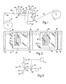
- a bag making operation is shown diagrammatically.
- a tubular printed web 10 is fed from a supply roll 11.
- the web 10 passes over tensioning rolls 13-16 and thence to a sealer station 18.
- An indicia responsive seal control detector is illustrated at 20.
- the machine, other than the detector and a control mechanism 21 which responds to its signals is of known construction and therefore not shown other than diagrammatically.
- the printing of the web 10 has not been shown. This printing can be accomplished conventionally except for the imprinting of the novel indicia of this invention. Since the preferred indicia on a multi-colored web will be superimposed over other printing in many instances, the other printing may be applied first and then the indicia registered relative to that other printing by conventional techniques. In that event, all subsequent printing operation are then desirably controlled by detection and control corresponding to that used in the illustrated bag manufacturing operations.
- the first printing operation will imprint printing machine control indicia which are used to control subsequent printing. If these indicia are overprinted by such subsequent printing, further indicia are applied, when the preferred material is used, so that the finished product will have use control indicia on an outer surface of the web.
- transverse seals are formed at regularly spaced intervals to delineate the ends of the interconnected bags.
- the sealer 18 includes a relatively soft roll 23 about which the web is tightly wrapped.
- the sealer 18 also includes a shuttle 24 having a heated resistive element 25 extending essentially from one side of the roll 23 to the other.
- a transverse heat seal 26 ( Figure 2) is formed.
- the timing of the engagement of the element 25 with the strip is chosen so that proper end seal spacings will be provided. This is controlled by the detector and control 20, 21 as will be described.
- the strip passes over a tensioning roll 27 and then to a perforating station 28.
- the perforating station 28 includes a roll which has a cylindrical body portion 30 with a toothed knife 32 extending from one side of the roll to the other.
- the knife acts against a backup roll 33 to puncture the superimposed layers of the tubular web 10. This puncturing at spaced locations provides uniformly spaced lines of weakness 35 in the form of closely spaced perforations extending from one edge of the web to the other ( Figure 2).
- a perforation control detector 36 is provided at the perforation station.
- the perforation detector 36 like the heat seal detector 20, is connected to the control 21. Coaction of the detector 36 and this control 21 assures proper registration of the perforations.
- the web 10 passes over the tensioning rolls 38, 39 and is coiled on a takeup roll 40.
- the control mechanism includes circuitry which in turn sends control signals to differential speed controls (not shown) associated with the seal and perforation stations 18, 28.
- the circuitry of the control 21 includes a comparator which produces no output when the detector signal is below a certain threshold or reference level and produces a control voltage when the detector signal exceeds the threshold.
- FIG 2 a section of a chain of interconnected bags formed by the apparatus of Figure 1 is shown.
- Each illustrated bag 45 includes a printed area 47.
- the depicted printing includes wavy lines 48 which are intended to indicate either informative or decorative printing.
- the printed areas are shown as rectangular for clarity of illustration but in practice the amount of, and appearance of, the printing will be dictated by the user's wishes.
- the bag may be anything from clear to fully covered with decorative and/or informative printing, and that printing may be of any color or color combination including a color which reflects radiation of the same wavelength as the electromagnetic radiation emitted by the indicia 42.
- the indicia 42 are superimposed over the printing and are transparent so that their presence does not interfere with the decoration and information in the printed areas.
- the bags are substantially identical in appearance to otherwise identical bags which do not bear indicia 42.
- the indicia 42 are seen spaced at regular intervals along the length of the web 10. In some applications the regularly spaced indicia extend across the entire width dimension of the web while in others they comprise regularly appearing spots along a certain portion of the web. Since the preferred indicia 42 are essentially invisible, they do not detract from the appearance of writing or a logo appearing on the printed area 47.
- FIG. 2 An alternative marking scheme 42' is illustrated in Figure 2.
- This scheme comprises a continuous, rather than an intermittent, marking which may be used to convey a greater amount of information than the intermittent scheme.
- the sinusoidal like wave form may be amplitude or frequency modulated, for example, to convey a modulating signal to one of the detectors. This signal is then transmitted to the control 21 for further transmission to work stations.
- the ink used for marking is comprised of a vehicle which dries clear and pigments which are normally invisible but which cause a shift in the wavelength of electromagnetic radiation in a limited, well defined, wavelength band. Tests have shown marking the web with an appropriate invisible ink to be somewhat of a problem.
- a web is stored in a roll on a mandrel until it is to be unwound for processing. When stored on a roll, it is necessary that the marking indicia 42 not "bleed through" or migrate among different layers of plastic thereby disrupting the well defined pattern of markings. The bleed through problem is especially pronounced when a plastic web such as low density polyethylene is utilized.
- low density polyethylene comprises the web structure through utilization of wavelength shifting components which do not migrate from one layer to the next in the stored web material.
- One chemical useful in applying a wave shifting mark to a low density polyethylene web material is a chemical commercially available under the name Sandoz Th-40 supplied by Sandoz Colors and Chemicals Corporation.
- Sandoz Th-40 is a disulfonated diamino stilbene-triazine in liquid form.
- the invisible marking material is manufactured using an ink comprising 93% varnish, 4% Sandoz Th-40 and 3% wax.
- the wax is commercially available from the Inmont Company under the designation 72 F9105.
- the varnish is a resin, alcohol mixture which in the preferred embodiment comprises 40% ver- samid 712 and 60% alcohol.
- the marking is printed to the plastic web using a suitable printing roller.
- FIG. 3 diagrammatically shows a bag filling machine, such as the machine described and claimed in U.S.-A-3,965,653 issued 29th June 1976 under the title Packaging Method and Apparatus, equipped with a detector adapted to sense the presence of indicia 42 and thereby control web feed.
- a coiled web of bags 51 is provided. The web is fed between feed rolls 52 to a load station 53. A flow of air from a nozzle 54 opens a bag 56 which is to be loaded. Parts 55 are fed through a funnel 57 to fill the bag once it is registered at the load station 53.
- An indicia detector is shown at 59.
- the control 21 which in turn controls a web feed motor 60.
- the control causes the motor 60 to stop driving the feed rolls 52 when the bag 56 has reached the station 53.
- a preferred detector unit 140 for detecting the presence of markings along a web is shown in Figures 4-6.
- This unit is the preferred unit to be used as the detector 20, the detector 36, and the detector 59 used to control bag dispensing, loading and sealing operations.
- the unit 140 is mounted in proximity to a moving web by a detector mounting plate.
- a web guide 144 is positioned beneath the detector 140 and is attached to it by a suitable support 146. This guide 144 allows the web to pass beneath the detector at a distance close enough to allow the detector to sense the presence of the marking on the web.
- Control circuitry 110 mounted inside the unit 140 (see Figure 4) generates control signals which allow either fabrication or manufacturing processes to be performed to the moving web.
- the radiation sources 150, 152 Positioned between these sources is a detector 154 which senses the presence of markings on the web as the web passes over the web guide 144.
- the radiation sources 150, 152 direct indicia stimulating electromagnetic radiation of about 3660 angstroms to the web and due to their positioning concentrate a high intensity of electromagnetic radiation directly beneath the detector 154.
- the incident radiation strikes the markings it causes a wave shifted output to be emitted from that marking.
- Sandoz Th-40 generates an output radiation with a wavelength of about 4500 angstroms.
- a filter 156 for filtering out electromagnetic radiation of wavelengths other than the wavelengths emitted by the marking.
- the filter enhances sensitivity by substantially preventing certain radiation reflected from the web from reaching the detector. More specifically the filter sufficiently blocks transmission of reflected indicia stimulating radiation so that such reflections will not cause false signals when indicia are not present. Reflection of electromagnetic radiation which is ambient to the machine is not a problem because its intensity, in any location occupied by humans, is not high enough to cause reflections which will cause the detector to emit false signals.
- Exemplary circuitry 110 for generating control voltages in response to the presence of the web markings is shown mounted inside the detector unit 140 on a printed circuit board 111. That circuitry 110 is electrically connected to a photo diode 113 in the detector 154. Three amplifiers 112,114,116 and a timer 118 respond to changes in photo diode resistance with changes in electromagnetic radiation intensity to generate a control output 120.
- An output 121 from a first operational amplifier 112 is coupled to a second operational amplifier 114 and further coupled to the inverting input of the first op amp 112 through a feedback network 122.
- the second operational amplifier 114 responds to the output 121 from the first amplifier 112.
- This second op amp 114 includes a reference input and a non-inverting input. When the non-inverting input signal is greater than the reference signal, an output 124 from the second operational amplifier 114 goes high.
- This output 124 is coupled to an industrial timer 118 which serves to shape the irregular shaped output 124 from the second amplifier 114 into a well defined signal of constant height and pulse width.
- the feedback network 122 comprises two parallel connected diode, resistor circuits 130, 132 and the third amplifier 116. As the output from the first amplifier increases one diode 134 conducts through a 1 megohm resistor and charges a 10 u farad capacitor 136. As that capacitor charges its voltage increases. This voltage is coupled to the third amplifier 116 and is transmitted by that gain of one amplifier to the inverting input of the first amplifier 112.
- the capacitor 136 will charge slowly and the feedback input to the first amplifier's inverting input will also change slowly, trailing the non-inverting input to the first amplifier. Since the output from the first amplifier is the difference in value between its two inputs the signal transmitted to the second amplifier 114 is constant or relatively so.
- a sharp, sudden rise of the output from the first amplifier 112 due to a sudden change in the current through the diode 113 causes a large signal to appear to the non-inverting input to the second amplifier 114 which triggers an output on ' the timer 118.
- the capacitor 136 cannot charge rapidly enough to significantly change the input to the third amplifier 116.
- the inverting input on the first amplifier does not change and therefore the difference between the two inputs remain large.
- the circuitry 110 is sensitive to rapid changes in radiation intensity and not gradual changes in ambient radiation intensity.
- the intensity changes neces - sary to actuate the output are determined by the reference input to the second amplifier 114 and can be varied according to the specific system being controlled. In the preferred and illustrated embodiment the reference input is about 1.2 volts.
- the .047 second output from the timer 118 signifies the presence of a control mark beneath the detector 154. Since this output may not be compatible with a particular control system it may be used to generate suitable control signals which are compatible with a particular control.
- the detector arrangement remains substantially unmodified.
- the filter 156 should be a 9050 angstrom band filter.
- the incident radiation must be in the 7950 angstrom range and can be generated by passing incandescent radiation through a 7560 angstrom band filter or using an infrared source that radiates 7950 angstrom radiation.
Landscapes
- Engineering & Computer Science (AREA)
- Mechanical Engineering (AREA)
- Advancing Webs (AREA)
- Polarising Elements (AREA)
- Preliminary Treatment Of Fibers (AREA)
- Controlling Rewinding, Feeding, Winding, Or Abnormalities Of Webs (AREA)
- Containers And Plastic Fillers For Packaging (AREA)
- Making Paper Articles (AREA)
- Treatment Of Fiber Materials (AREA)
Claims (15)
Priority Applications (1)
| Application Number | Priority Date | Filing Date | Title |
|---|---|---|---|
| AT81303068T ATE13650T1 (de) | 1980-07-07 | 1981-07-06 | Kontinuierliche registrierung einer folienbahn. |
Applications Claiming Priority (2)
| Application Number | Priority Date | Filing Date | Title |
|---|---|---|---|
| US16650080A | 1980-07-07 | 1980-07-07 | |
| US166500 | 1980-07-07 |
Publications (3)
| Publication Number | Publication Date |
|---|---|
| EP0043723A2 EP0043723A2 (fr) | 1982-01-13 |
| EP0043723A3 EP0043723A3 (en) | 1982-04-07 |
| EP0043723B1 true EP0043723B1 (fr) | 1985-06-05 |
Family
ID=22603581
Family Applications (1)
| Application Number | Title | Priority Date | Filing Date |
|---|---|---|---|
| EP81303068A Expired EP0043723B1 (fr) | 1980-07-07 | 1981-07-06 | Enregistrement continu d'une bande |
Country Status (4)
| Country | Link |
|---|---|
| EP (1) | EP0043723B1 (fr) |
| JP (1) | JPS5757158A (fr) |
| AT (1) | ATE13650T1 (fr) |
| DE (1) | DE3170829D1 (fr) |
Families Citing this family (14)
| Publication number | Priority date | Publication date | Assignee | Title |
|---|---|---|---|---|
| US4485982A (en) * | 1982-11-24 | 1984-12-04 | Xerox Corporation | Web tracking system |
| DE3341539A1 (de) * | 1983-11-17 | 1985-05-30 | Focke & Co, 2810 Verden | Einrichtung zur ueberwachung und steuerung von bahnen in verpackungsmaschinen |
| US4835720A (en) * | 1986-03-11 | 1989-05-30 | Adolph Coors Company | Obstructed-field-indicia-sensing device |
| NL9101904A (nl) * | 1991-11-15 | 1993-06-01 | Jongerius Bv | Werkwijze en inrichting voor het in een zak verpakken van brood. |
| US5458062A (en) * | 1994-02-28 | 1995-10-17 | Goldberg; Ira B. | Continuous web printing press with page cutting control apparatus and method |
| JPH09188357A (ja) * | 1995-12-29 | 1997-07-22 | Nippon Tetrapack Kk | 非可視性情報を含む包材、非可視性情報を含む包装容器及び、充填包装法 |
| SE521876C2 (sv) | 1999-12-22 | 2003-12-16 | Tetra Laval Holdings & Finance | Flerstegsenhet för bearbetning av ett banformat förpackningsmaterial i en maskin för förpackning av livsmedel |
| US6885451B2 (en) | 2002-03-09 | 2005-04-26 | Kimberly-Clark Worldwide, Inc. | Infrared detection of composite article components |
| US6900450B2 (en) | 2002-03-09 | 2005-05-31 | Kimberly-Clark Worldwide, Inc. | Method and apparatus for inferring item position based on multiple data |
| US6919965B2 (en) | 2002-03-09 | 2005-07-19 | Kimberly-Clark Worldwide, Inc. | Apparatus and method for making and inspecting pre-fastened articles |
| US6888143B2 (en) | 2002-03-09 | 2005-05-03 | Kimberly-Clark Worldwide, Inc. | Apparatus and method for inspecting pre-fastened articles |
| US6927857B2 (en) * | 2002-03-09 | 2005-08-09 | Kimberly-Clark Worldwide, Inc. | Process for the detection of marked components of a composite article using infrared blockers |
| EP2115543B1 (fr) | 2007-01-11 | 2012-10-31 | 3M Innovative Properties Company | Détecteur de position longitudinale de nappe |
| JP5948809B2 (ja) * | 2011-11-18 | 2016-07-06 | セイコーエプソン株式会社 | ターゲット搬送装置及び液体噴射装置 |
Family Cites Families (12)
| Publication number | Priority date | Publication date | Assignee | Title |
|---|---|---|---|---|
| US2400447A (en) * | 1940-04-25 | 1946-05-14 | American Mach & Foundry | Web-registering device |
| US3237973A (en) * | 1962-10-10 | 1966-03-01 | Pateco | Magnetically orientable wrapping materials and method of making and using same |
| US3254828A (en) * | 1963-12-18 | 1966-06-07 | Automated Packaging Corp | Flexible container strips |
| US3566120A (en) * | 1968-09-25 | 1971-02-23 | American Cyanamid Co | Method of coded data storage by means of coded inks in which the code components have particular absorption bands in the infrared |
| JPS4915882B1 (fr) * | 1969-08-04 | 1974-04-18 | ||
| DE1939862A1 (de) * | 1969-08-05 | 1971-02-18 | Schmall Geb Mutschler | Etikett zur Verwendung in automatischen Etikettiermaschinen |
| US3641733A (en) * | 1970-06-05 | 1972-02-15 | Automated Packaging Syst Inc | Method and apparatus for loading and forming envelopes and blank envelope structure used therewith |
| US3965653A (en) * | 1971-05-03 | 1976-06-29 | Bernard Lerner | Packaging apparatus |
| JPS5228391B2 (fr) * | 1972-04-15 | 1977-07-26 | ||
| JPS5925811B2 (ja) * | 1973-03-27 | 1984-06-21 | 三菱製紙株式会社 | 耐光性のすぐれた螢光体の製造方法 |
| US3968350A (en) * | 1974-07-17 | 1976-07-06 | Xerox Corporation | Article labeling apparatus and label form therefor |
| DE2553811C3 (de) * | 1975-11-29 | 1979-10-04 | Rudolf 7210 Rottweil Hopt | Maschinell lesbarer Datenträger und Vorrichtung zum Prüfen desselben |
-
1981
- 1981-07-06 AT AT81303068T patent/ATE13650T1/de not_active IP Right Cessation
- 1981-07-06 EP EP81303068A patent/EP0043723B1/fr not_active Expired
- 1981-07-06 JP JP56104547A patent/JPS5757158A/ja active Pending
- 1981-07-06 DE DE8181303068T patent/DE3170829D1/de not_active Expired
Also Published As
| Publication number | Publication date |
|---|---|
| DE3170829D1 (en) | 1985-07-11 |
| ATE13650T1 (de) | 1985-06-15 |
| JPS5757158A (en) | 1982-04-06 |
| EP0043723A3 (en) | 1982-04-07 |
| EP0043723A2 (fr) | 1982-01-13 |
Similar Documents
| Publication | Publication Date | Title |
|---|---|---|
| US4680205A (en) | Continuous web registration | |
| US4945252A (en) | Continuous web registration | |
| EP0043723B1 (fr) | Enregistrement continu d'une bande | |
| US4926048A (en) | Process of performing work on a continuous web | |
| US4467207A (en) | Non-migrating control indicia for a plastic web or sheet article | |
| US5674347A (en) | Apparatus and method for preparing printing labels | |
| US3536550A (en) | Method of and apparatus for printing and feeding labels in a continuous web,and for verifying and cutting individual labels therefrom for application to articles | |
| CN102245389B (zh) | 控制带状材料上印刷图案与非印刷图案之间的相对位置的方法以及在该方法中使用的系统 | |
| US6027820A (en) | Continuous web registration | |
| ES2429065T3 (es) | Aparato para aplicar diversas etiquetas codificadas a productos agrícolas | |
| US5488480A (en) | Apparatus and method for detecting a heat seal in a moving plastic film | |
| EP0929474B1 (fr) | Materiau d'emballage portant des renseignements invisibles | |
| US4585254A (en) | Label assembly with verifying means and method of making and using | |
| EP1386842A1 (fr) | Dispositif pour l'impression et l'application de rubans adhésifs sur des surfaces | |
| CN101400328A (zh) | 在同步定位至少一个基本连续材料织物中使用的、用于检测同步标记的方法和装置 | |
| US6766953B1 (en) | Tape indicia on clear film media | |
| US4698514A (en) | Method and an arrangement for the detection by photoelectric means of markings made on a travelling material web provided with printed decoration | |
| US3955502A (en) | Method of printing labels | |
| EP0686564B1 (fr) | Appareil et procédé pour la fabrication d'emballages blister étiquetés et interconnectés | |
| US6358353B1 (en) | Label scanning system | |
| CA1173136A (fr) | Alignement d'une bande de papier en defilement | |
| CN110300663B (zh) | 一种用于包装材料的印刷系统 | |
| EP0043724B1 (fr) | Répères de commande transformant la longueur d'onde électromagnétique pour bande ou feuille en matierè plastique | |
| US20230311475A1 (en) | A method and system for printing | |
| EP0837774B1 (fr) | Systeme de scannage d'etiquettes |
Legal Events
| Date | Code | Title | Description |
|---|---|---|---|
| PUAI | Public reference made under article 153(3) epc to a published international application that has entered the european phase |
Free format text: ORIGINAL CODE: 0009012 |
|
| AK | Designated contracting states |
Designated state(s): AT BE CH DE FR GB IT LU NL SE |
|
| PUAL | Search report despatched |
Free format text: ORIGINAL CODE: 0009013 |
|
| AK | Designated contracting states |
Designated state(s): AT BE CH DE FR GB IT LU NL SE |
|
| RHK1 | Main classification (correction) |
Ipc: B65B 43/12 |
|
| 17P | Request for examination filed |
Effective date: 19821002 |
|
| ITF | It: translation for a ep patent filed | ||
| GRAA | (expected) grant |
Free format text: ORIGINAL CODE: 0009210 |
|
| AK | Designated contracting states |
Designated state(s): AT BE CH DE FR GB IT LI LU NL SE |
|
| REF | Corresponds to: |
Ref document number: 13650 Country of ref document: AT Date of ref document: 19850615 Kind code of ref document: T |
|
| REF | Corresponds to: |
Ref document number: 3170829 Country of ref document: DE Date of ref document: 19850711 |
|
| ET | Fr: translation filed | ||
| PLBE | No opposition filed within time limit |
Free format text: ORIGINAL CODE: 0009261 |
|
| STAA | Information on the status of an ep patent application or granted ep patent |
Free format text: STATUS: NO OPPOSITION FILED WITHIN TIME LIMIT |
|
| 26N | No opposition filed | ||
| ITTA | It: last paid annual fee | ||
| EPTA | Lu: last paid annual fee | ||
| EAL | Se: european patent in force in sweden |
Ref document number: 81303068.1 |
|
| PGFP | Annual fee paid to national office [announced via postgrant information from national office to epo] |
Ref country code: AT Payment date: 20000612 Year of fee payment: 20 |
|
| PGFP | Annual fee paid to national office [announced via postgrant information from national office to epo] |
Ref country code: SE Payment date: 20000620 Year of fee payment: 20 |
|
| PGFP | Annual fee paid to national office [announced via postgrant information from national office to epo] |
Ref country code: FR Payment date: 20000621 Year of fee payment: 20 Ref country code: CH Payment date: 20000621 Year of fee payment: 20 |
|
| PGFP | Annual fee paid to national office [announced via postgrant information from national office to epo] |
Ref country code: GB Payment date: 20000622 Year of fee payment: 20 |
|
| PGFP | Annual fee paid to national office [announced via postgrant information from national office to epo] |
Ref country code: NL Payment date: 20000627 Year of fee payment: 20 |
|
| PGFP | Annual fee paid to national office [announced via postgrant information from national office to epo] |
Ref country code: DE Payment date: 20000629 Year of fee payment: 20 |
|
| PGFP | Annual fee paid to national office [announced via postgrant information from national office to epo] |
Ref country code: BE Payment date: 20000704 Year of fee payment: 20 |
|
| PGFP | Annual fee paid to national office [announced via postgrant information from national office to epo] |
Ref country code: LU Payment date: 20000712 Year of fee payment: 20 |
|
| BE20 | Be: patent expired |
Free format text: 20010706 *AUTOMATED PACKAGING SYSTEMS INC. |
|
| PG25 | Lapsed in a contracting state [announced via postgrant information from national office to epo] |
Ref country code: LI Free format text: LAPSE BECAUSE OF EXPIRATION OF PROTECTION Effective date: 20010705 Ref country code: GB Free format text: LAPSE BECAUSE OF EXPIRATION OF PROTECTION Effective date: 20010705 Ref country code: CH Free format text: LAPSE BECAUSE OF EXPIRATION OF PROTECTION Effective date: 20010705 |
|
| PG25 | Lapsed in a contracting state [announced via postgrant information from national office to epo] |
Ref country code: NL Free format text: LAPSE BECAUSE OF EXPIRATION OF PROTECTION Effective date: 20010706 Ref country code: LU Free format text: LAPSE BECAUSE OF EXPIRATION OF PROTECTION Effective date: 20010706 Ref country code: AT Free format text: LAPSE BECAUSE OF EXPIRATION OF PROTECTION Effective date: 20010706 |
|
| REG | Reference to a national code |
Ref country code: GB Ref legal event code: PE20 Effective date: 20010705 |
|
| PG25 | Lapsed in a contracting state [announced via postgrant information from national office to epo] |
Ref country code: SE Free format text: THE PATENT HAS BEEN ANNULLED BY A DECISION OF A NATIONAL AUTHORITY Effective date: 20010730 |
|
| REG | Reference to a national code |
Ref country code: CH Ref legal event code: PL |
|
| NLV7 | Nl: ceased due to reaching the maximum lifetime of a patent |
Effective date: 20010706 |
|
| EUG | Se: european patent has lapsed |
Ref document number: 81303068.1 |