EP0042824B2 - Mähdrescher mit abnehmbarer Dresch- und Trenneinrichtung - Google Patents
Mähdrescher mit abnehmbarer Dresch- und Trenneinrichtung Download PDFInfo
- Publication number
- EP0042824B2 EP0042824B2 EP81830090A EP81830090A EP0042824B2 EP 0042824 B2 EP0042824 B2 EP 0042824B2 EP 81830090 A EP81830090 A EP 81830090A EP 81830090 A EP81830090 A EP 81830090A EP 0042824 B2 EP0042824 B2 EP 0042824B2
- Authority
- EP
- European Patent Office
- Prior art keywords
- threshing
- combine harvester
- transverse
- cylinder
- separating unit
- Prior art date
- Legal status (The legal status is an assumption and is not a legal conclusion. Google has not performed a legal analysis and makes no representation as to the accuracy of the status listed.)
- Expired
Links
- 238000004140 cleaning Methods 0.000 claims description 14
- 239000010902 straw Substances 0.000 claims description 4
- 239000000725 suspension Substances 0.000 claims description 4
- 238000007599 discharging Methods 0.000 claims description 3
- 238000011144 upstream manufacturing Methods 0.000 claims description 3
- 239000000463 material Substances 0.000 description 9
- 241001124569 Lycaenidae Species 0.000 description 2
- 238000002485 combustion reaction Methods 0.000 description 1
- 238000000926 separation method Methods 0.000 description 1
- 239000004575 stone Substances 0.000 description 1
- 238000010408 sweeping Methods 0.000 description 1
- 230000032258 transport Effects 0.000 description 1
Images
Classifications
-
- A—HUMAN NECESSITIES
- A01—AGRICULTURE; FORESTRY; ANIMAL HUSBANDRY; HUNTING; TRAPPING; FISHING
- A01F—PROCESSING OF HARVESTED PRODUCE; HAY OR STRAW PRESSES; DEVICES FOR STORING AGRICULTURAL OR HORTICULTURAL PRODUCE
- A01F12/00—Parts or details of threshing apparatus
-
- A—HUMAN NECESSITIES
- A01—AGRICULTURE; FORESTRY; ANIMAL HUSBANDRY; HUNTING; TRAPPING; FISHING
- A01F—PROCESSING OF HARVESTED PRODUCE; HAY OR STRAW PRESSES; DEVICES FOR STORING AGRICULTURAL OR HORTICULTURAL PRODUCE
- A01F12/00—Parts or details of threshing apparatus
- A01F12/18—Threshing devices
Definitions
- the present invention relates to combine harvesters.
- the invention concerns a combine harvester comprising a cutting table, and an axial-flow threshing and separating unit mounted transversely relative to the longtudinal axis of the combine harvester, said axial flow and separating unit including a threshing and separating cylinder, a counterbeater substantially in the form of a concave grille which surrounds a lower part of a first portion of the threshing and separating cylinder, and a separator casing substantially in the form of a tubular grille which surrounds a second portion of the threshing and separating cylinder.
- Combine harvesters having transversely mounted axial-flow threshing and separating units are known-see, for example, US-1 932 714. In these machines the harvested crop follows a helical path around the threshing and separating cylinder while moving axially from one to the other. This produces an efficient threshing action and better grain separation.
- the object of the present invention is to provide a combine harvester of the type specified above which is simple in structure and easily dismantled into different units of relatively small size, thus enabling the assembly, disassembly and transportation of the machine to be effected quickly and simply.
- the present invention provides a combine harvester of the aforesaid type, the main characteristic of which is that the threshing and separating unit is mounted by a support structure releasably fixed to the cutting table, said support structure including a transverse feed cylinder which is located upstream of the threshing and separating unit to feed a harvested crop to said unit, said transverse feed cylinder being mounted on a shaft, each end of which is supported on said structure by resent suspension means, said support structure further including an auger located immediately below the delivery end of the threshing and separating unit for discharging straw, a grain collection recess located below the threshing and separating unit and a transverse auger adjacent said recess, with oppositely-wound spirals which converge towards a central section including two paddles for conveying the grain towards a blade elevator.
- the whole unit formed by the cutting table and the threshing and separating unit may be easily separated from the remainder of the machine.
- the threshing and separating unit may be removed from the cutting table, further simplifying transportation of the machine.
- the particular structure and arrangement of the various elements constituting the threshing and separating unit enable efficient operation of the latter.
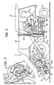
- a combine harvester including a chassis 2, which is supported by front and rear wheels 3, 4, and an internal combustion engine 5.
- the combine harvester 1 has a cutting table 6 which includes a known type of feed auger 7 with retractable fingers 8 (also of known type).
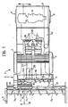
- a structure 9 which carries an axial-flow threshing and separating unit generally indicated 10.
- the threshing and separating unit 10 which is of known type, comprises a threshing and separating cylinder 11 disposed transversely relative to the longitudinal axis of the machine, a counter-beater 12 formed by a concave grille which surrounds a lower part of one portion of the threshing and separating cylinder 11, and a separator casing 13 which is formed by a tubular grille surrounding that portion of the cylinder 11 not covered by the counter-beater 12.
- a transverse feed cylinder 14 is located upstream of the threshing and separating unit 10 for receiving the crop from the auger 7 and conveying it to the unit 10.
- the feed auger 7 has two sections 7a, 7b with spirals converging centrally towards an intermediate section 7c which is provided with fingers 8 and in correspondence with which the transverse feed cylinder 14 is located.
- a collection recess 15 is located beneath the unit 10 and houses a transverse auger 16.
- the transverse auger 16 comprises two sections 16a, 16b with spirals which converge centrally towards an intermediate section 16c incorporating two paddles 16d.
- a greater-diameter transverse auger 17 is fitted coaxially with the auger 16 and adjacent the delivery end of the threshing and separating unit 10, to discharge the straw emerging from the unit 10.
- the transverse feed cylinder 14 is mounted on a shaft 18 which is fixed at each end to a plate 19 articulated about a horizontal transverse axis 20 to a front part of the structure 9 carrying the threshing and separating unit 10.
- the ends of the shaft 18 are slidable in two guide slots 21 made laterally in this structure.
- each plate 19 there is also articulated a tie rod 22 which is fitted slidingly in a support 23 with a part (not visible in Figure 3) which is fixed to the structure 9.
- each tie rod 22 is connected a spring 24 which is interposed between the support 23 and an engagement member 25 fixed to the rod 22.
- the transverse feed cylinder 14 can oscillate on its resilient suspension and adapt to the volume of the crop being fed from the auger 7.
- a flap 14a which is articulated to the structure 9 about a transverse axis 14b and is resiliently biassed to a closed position where it is held by a trip device (not illustrated).
- the flap 14a opens downwards when it is hit sharply by a hard body, such as a stone, preventing the latter from being pushed under the cylinder 11.
- the combine harvester 1 includes a pair of blade elevators 26, 27 which are arranged in series to receive the crop fed from the auger 16 by the paddles 16d in the section 16c, and carry it to a delivery end 28 next to the crop cleaning means of the machine.
- the purpose of the augers 29 is to distribute the crop across the whole width of the machine.
- a blade-type transverse acclerator roller 30 which accelerates the descent of the crop from the augers 29 to the cleaning means of the machine, generally indicated 31.
- the cleaning means 31 comprises two superimposed cleaning screens 32 of known type associated with two fans 33 which direct an upward blast of air at the crop falling onto the screens 32.
- a shaking chute 34 which conveys the crop to the screens 32.
- Associated with the chute 34 are three fans 35 (only one of which is shown in Figure 2) which direct an upward blast of air at the crop falling onto the shaking chute 34.
- an auger 36 for carrying the clean grain to the storage tank 37 of the machine, and an auger 38 for recovered material.
- the auger 36 for transporting the clean grain to the storage tank 37 is associated with a screw- type elevator 39, whilst the auger 38 for the recovered material is associated with a centrifugal beater 40, of known type, which causes the material thus conveyed to fall onto the cleaning screens 32 again.
- the elevator 39 is arranged vertically in the centre of the storage tank 37, to ensure even filling of the latter.
- the combine harvester further includes a known type of swivelling conveyor 41 for discharging the grain from the storage tank 37.
- the threshing and separating unit 10 is provided with a sweeping device of known type, as shown diagrammatically in Figure 2 by refence numeral 42, for removing the material which is separated by the upper portion of the grille forming the separator casing 13, and conveying it directly towards the collection recess 15 or a transverse auger 43 (see also Figure 1) which is located in a channel-shaped wall located above and in front of the entrance to the unit 10.
- the auger 43 transports the material towards the collection recess (15).
- the crop is fed by the feed cylinder 14 to the right-hand side of the threshing and separating unit 10.
- the straw, or any material over a certain length, is discharged into the auger 17 and thrown outwards to the ground to form a windrow alongside the machine.
- the grain separated by the counter-beater 12 and the separator 13 is collected in the recess 15, where the sections 16a, 16b of the auger feed it to the part of the recess 15 corresponding to the middle section 16c of the auger 16.
- the grain concentrated in the section 16c of the auger 16 is thrust by the paddles 16d to wards the blade elevator 26, and is transported by the latter, and the blade elevator 27, to the delivery end 28 and the contra-rotating augers 29, which distribute the grain across the whole width of the machine.
- the accelerator roller 30, which is of the rubber paddle type, rotates at high speed and accelerates the fall of the grain onto the shaking chute 34. As it falls, the grain is subjected to the upward blast of air produced by the three fans 35, and the majority of the light material is removed and discharged to the ground.
- the crop passes from the shaking chute 34 to the cleaning screens 32 of conventional type where it is subjected to the blast of air produced by the fans 33.
- the lighter material is discharged to the ground whilst the clean grain is collected by the auger 36 which feeds it, via the screw elevator 39, to the storage tank 37 of the machine.
- the material which has been collected by the auger 38 is recycled by the centrifugal beater 40.
- the combine harvester according to the present invention has a structure which can be broken down into three main units: the cutting table 6, the threshing and separating unit support structure 9, and the rear part of the machine with the motor unit 5, the cleaning means 31 and the grain storage tank 37.
- the cylinder 14 may comprise a cylinder with retractable fingers, or a bladed cylinder.
Landscapes
- Life Sciences & Earth Sciences (AREA)
- Environmental Sciences (AREA)
- Threshing Machine Elements (AREA)
- Harvester Elements (AREA)
Claims (9)
Applications Claiming Priority (2)
| Application Number | Priority Date | Filing Date | Title |
|---|---|---|---|
| IT8053321U IT8053321V0 (it) | 1980-06-19 | 1980-06-19 | Macchina mietitrebbiatrice provvista di gruppo battitore separatore a flusso assiale |
| IT5332180U | 1980-06-19 |
Publications (3)
| Publication Number | Publication Date |
|---|---|
| EP0042824A1 EP0042824A1 (de) | 1981-12-30 |
| EP0042824B1 EP0042824B1 (de) | 1984-08-22 |
| EP0042824B2 true EP0042824B2 (de) | 1989-04-19 |
Family
ID=11281769
Family Applications (1)
| Application Number | Title | Priority Date | Filing Date |
|---|---|---|---|
| EP81830090A Expired EP0042824B2 (de) | 1980-06-19 | 1981-06-02 | Mähdrescher mit abnehmbarer Dresch- und Trenneinrichtung |
Country Status (5)
| Country | Link |
|---|---|
| US (1) | US4399825A (de) |
| EP (1) | EP0042824B2 (de) |
| CA (1) | CA1152409A (de) |
| DE (1) | DE3165668D1 (de) |
| IT (1) | IT8053321V0 (de) |
Families Citing this family (18)
| Publication number | Priority date | Publication date | Assignee | Title |
|---|---|---|---|---|
| IT1151166B (it) * | 1981-06-30 | 1986-12-17 | Claas Ohg | Mietitrebbiatrice semovente |
| DE3223927A1 (de) * | 1982-06-26 | 1983-12-29 | Claas Ohg, 4834 Harsewinkel | Selbstfahrender maehdrescher |
| IT8153561U1 (it) * | 1981-08-28 | 1983-02-28 | Laverda Spa Pietro | Macchina mietitrebbiatrice. |
| US4663921A (en) * | 1982-04-23 | 1987-05-12 | Deere & Company | Combine harvester with header-mounted separator |
| DE3307633C2 (de) * | 1983-03-04 | 1994-08-25 | Claas Ohg | Selbstfahrender Mähdrescher |
| IT1159988B (it) * | 1983-11-30 | 1987-03-04 | Laverda Spa Pietro | Perfezionamenti alle macchine mietitrebbiatrici |
| DE3511913C2 (de) * | 1985-04-01 | 1994-02-03 | Claas Ohg | Selbstfahrender Mähdrescher |
| DE3738991C2 (de) * | 1987-11-17 | 1994-06-16 | Claas Ohg | Selbstfahrender Mähdrescher |
| US4936810A (en) * | 1989-05-05 | 1990-06-26 | Ford New Holland, Inc. | Crop thinning elements for axial flow combine |
| US6551186B2 (en) | 2001-06-06 | 2003-04-22 | Agco Corporation | Beater for a combine harvester |
| GB0710994D0 (en) * | 2007-06-08 | 2007-07-18 | Agco Do Brasil Com E Ind Stria | Combines |
| BE1021154B1 (nl) * | 2013-07-02 | 2016-10-26 | Cnh Industrial Belgium Nv | Maaidorser met meertrapsgraanvoorbereiding |
| US10225988B2 (en) * | 2014-11-14 | 2019-03-12 | Cnh Industrial America Llc | Agricultural elevator supplied by multiple cross augers |
| US9686918B2 (en) * | 2015-10-08 | 2017-06-27 | Cnh Industrial America Llc | Combine with free grain extraction |
| JP7061940B2 (ja) * | 2018-07-30 | 2022-05-02 | 株式会社クボタ | コンバイン |
| US11147214B2 (en) * | 2019-06-26 | 2021-10-19 | Deere & Company | Combine with a pre-thresher |
| CN110583247B (zh) * | 2019-10-25 | 2022-08-16 | 周洁 | 一种花生脱粒装置 |
| DE102024000080B3 (de) | 2024-01-11 | 2025-03-13 | Johann Rumpler | Verfahren zur Ernte von Druschfrüchten und Erntevorrichtung zur Durchführung des Verfahrens zur Ernte von Druschfrüchten |
Family Cites Families (15)
| Publication number | Priority date | Publication date | Assignee | Title |
|---|---|---|---|---|
| AT121263B (de) * | 1928-01-21 | 1931-02-10 | Felix Dr Schlayer | Axialdresch- und -strohzerreißmaschine mit Reinigungsvorrichtung für das behandelte Dreschgut. |
| US1932714A (en) * | 1929-05-28 | 1933-10-31 | Caterpilar Tractor Co | Harvester |
| FR1148919A (fr) * | 1955-03-21 | 1957-12-18 | Dispositif pour séparer les grains et semences des pailles et autres parties de plantes | |
| GB891442A (en) * | 1959-06-09 | 1962-03-14 | Ford Motor Co | Harvester head |
| BE596800A (fr) * | 1959-11-07 | 1961-03-01 | Sigmund Stokland | Machine à battre le grain. |
| NL126694C (de) * | 1965-02-03 | |||
| US3391523A (en) * | 1965-03-08 | 1968-07-09 | Mcbain Frank | Rotary straw deck and sieveless chaffer |
| US3527233A (en) * | 1968-02-14 | 1970-09-08 | Mathews B C | Mounting means for threshing cylinder and header spout |
| US3593719A (en) * | 1969-04-02 | 1971-07-20 | Massey Ferguson Ind Ltd | Combine with three-stage separation |
| DE2037659A1 (de) * | 1969-07-30 | 1971-04-22 | Clayson N V Zedelgem (Belgien) | Mähdrescher |
| US3604427A (en) * | 1970-01-26 | 1971-09-14 | Allis Chalmers Mfg Co | Combine harvester |
| US3659403A (en) * | 1970-06-01 | 1972-05-02 | Allis Chalmers Mfg Co | Floating feeder beater |
| GB1479269A (en) * | 1973-07-25 | 1977-07-13 | Massey Ferguson Sa | Crop harvesting and threshing machines |
| US4060960A (en) * | 1976-04-22 | 1977-12-06 | Deere & Company | Self-propelled crop harvester |
| US4154250A (en) * | 1978-03-03 | 1979-05-15 | Allis-Chalmers Corporation | Drive mechanism and support arrangement for agitator of axial flow threshing cylinder |
-
1980
- 1980-06-19 IT IT8053321U patent/IT8053321V0/it unknown
-
1981
- 1981-06-02 EP EP81830090A patent/EP0042824B2/de not_active Expired
- 1981-06-02 DE DE8181830090T patent/DE3165668D1/de not_active Expired
- 1981-06-03 US US06/270,205 patent/US4399825A/en not_active Expired - Fee Related
- 1981-06-11 CA CA000379577A patent/CA1152409A/en not_active Expired
Also Published As
| Publication number | Publication date |
|---|---|
| EP0042824A1 (de) | 1981-12-30 |
| DE3165668D1 (en) | 1984-09-27 |
| EP0042824B1 (de) | 1984-08-22 |
| IT8053321V0 (it) | 1980-06-19 |
| US4399825A (en) | 1983-08-23 |
| CA1152409A (en) | 1983-08-23 |
Similar Documents
| Publication | Publication Date | Title |
|---|---|---|
| EP0042824B1 (de) | Mähdrescher mit abnehmbarer Dresch- und Trenneinrichtung | |
| US3589111A (en) | Combine harvester | |
| US4492237A (en) | Rotary combine | |
| US4067343A (en) | Grain conveyor means | |
| US2333901A (en) | Corn harvester | |
| EP3172959B1 (de) | Häcksler und streuer für eine landwirtschaftliche erntemaschine | |
| US10306834B2 (en) | Chopper and spreader for an agricultural harvester | |
| CA1112975A (en) | Isolated pneumatic cleaning system | |
| US4270550A (en) | Combine harvester | |
| US2875768A (en) | Auxiliary threshing and conveying unit | |
| EP3432702B1 (de) | Mähdrescherkornreinigungssystem | |
| US3439683A (en) | Axial flow combine | |
| US5077964A (en) | Crop harvesting method and apparatus | |
| US4178944A (en) | Tailings return for an axial flow combine | |
| US4619413A (en) | Forage or picking harvester | |
| US20020155867A1 (en) | Transfer mechanism for feeding harvested crop to a separation unit | |
| US4338955A (en) | Combine harvester having an axial-flow threshing and separating unit | |
| US2957293A (en) | Corn harvester | |
| US3213598A (en) | Dust dispersal fan | |
| US1841718A (en) | Composite conveying mechanism for combines | |
| EP0186630B1 (de) | Mähdrescher | |
| EP0042825B1 (de) | Mähdrescher mit Trenneinrichtung der Axialflussbauart | |
| US1831216A (en) | Thrashing | |
| US2109436A (en) | Harvester and thresher | |
| GB2051541A (en) | Combine harvesters |
Legal Events
| Date | Code | Title | Description |
|---|---|---|---|
| PUAI | Public reference made under article 153(3) epc to a published international application that has entered the european phase |
Free format text: ORIGINAL CODE: 0009012 |
|
| AK | Designated contracting states |
Designated state(s): BE DE FR GB IT NL SE |
|
| 17P | Request for examination filed |
Effective date: 19820325 |
|
| DET | De: translation of patent claims | ||
| ITF | It: translation for a ep patent filed | ||
| GRAA | (expected) grant |
Free format text: ORIGINAL CODE: 0009210 |
|
| AK | Designated contracting states |
Designated state(s): BE DE FR GB IT NL SE |
|
| REF | Corresponds to: |
Ref document number: 3165668 Country of ref document: DE Date of ref document: 19840927 |
|
| ET | Fr: translation filed | ||
| PLBI | Opposition filed |
Free format text: ORIGINAL CODE: 0009260 |
|
| 26 | Opposition filed |
Opponent name: CLAAS OHG Effective date: 19850511 |
|
| NLR1 | Nl: opposition has been filed with the epo |
Opponent name: CLAAS OHG |
|
| RAP2 | Party data changed (patent owner data changed or rights of a patent transferred) |
Owner name: FIATGEOTECH - TECNOLOGIE PER LA TERRA S.P.A. |
|
| NLT2 | Nl: modifications (of names), taken from the european patent patent bulletin |
Owner name: FIATGEOTECH-TECNOLOGIE PER LA TERRA S.P.A. TE MODE |
|
| PUAH | Patent maintained in amended form |
Free format text: ORIGINAL CODE: 0009272 |
|
| STAA | Information on the status of an ep patent application or granted ep patent |
Free format text: STATUS: PATENT MAINTAINED AS AMENDED |
|
| 27A | Patent maintained in amended form |
Effective date: 19890419 |
|
| AK | Designated contracting states |
Kind code of ref document: B2 Designated state(s): BE DE FR GB IT NL SE |
|
| ITF | It: translation for a ep patent filed | ||
| ET3 | Fr: translation filed ** decision concerning opposition | ||
| NLR2 | Nl: decision of opposition | ||
| NLR3 | Nl: receipt of modified translations in the netherlands language after an opposition procedure | ||
| PGFP | Annual fee paid to national office [announced via postgrant information from national office to epo] |
Ref country code: GB Payment date: 19920515 Year of fee payment: 12 |
|
| PGFP | Annual fee paid to national office [announced via postgrant information from national office to epo] |
Ref country code: BE Payment date: 19920520 Year of fee payment: 12 |
|
| PGFP | Annual fee paid to national office [announced via postgrant information from national office to epo] |
Ref country code: DE Payment date: 19920521 Year of fee payment: 12 |
|
| PGFP | Annual fee paid to national office [announced via postgrant information from national office to epo] |
Ref country code: SE Payment date: 19920526 Year of fee payment: 12 |
|
| ITTA | It: last paid annual fee | ||
| PGFP | Annual fee paid to national office [announced via postgrant information from national office to epo] |
Ref country code: NL Payment date: 19920630 Year of fee payment: 12 Ref country code: FR Payment date: 19920630 Year of fee payment: 12 |
|
| PG25 | Lapsed in a contracting state [announced via postgrant information from national office to epo] |
Ref country code: GB Effective date: 19930602 |
|
| PG25 | Lapsed in a contracting state [announced via postgrant information from national office to epo] |
Ref country code: SE Effective date: 19930603 |
|
| PG25 | Lapsed in a contracting state [announced via postgrant information from national office to epo] |
Ref country code: BE Effective date: 19930630 |
|
| BERE | Be: lapsed |
Owner name: FIATGEOTECH - TECNOLOGIE PER LA TERRA S.P.A. Effective date: 19930630 |
|
| PG25 | Lapsed in a contracting state [announced via postgrant information from national office to epo] |
Ref country code: NL Effective date: 19940101 |
|
| GBPC | Gb: european patent ceased through non-payment of renewal fee |
Effective date: 19930602 |
|
| NLV4 | Nl: lapsed or anulled due to non-payment of the annual fee | ||
| PG25 | Lapsed in a contracting state [announced via postgrant information from national office to epo] |
Ref country code: FR Effective date: 19940228 |
|
| PG25 | Lapsed in a contracting state [announced via postgrant information from national office to epo] |
Ref country code: DE Effective date: 19940301 |
|
| REG | Reference to a national code |
Ref country code: FR Ref legal event code: ST |
|
| EUG | Se: european patent has lapsed |
Ref document number: 81830090.7 Effective date: 19940110 |
|
| APAH | Appeal reference modified |
Free format text: ORIGINAL CODE: EPIDOSCREFNO |