EP0042178B1 - Absolutcodierer - Google Patents
Absolutcodierer Download PDFInfo
- Publication number
- EP0042178B1 EP0042178B1 EP81104659A EP81104659A EP0042178B1 EP 0042178 B1 EP0042178 B1 EP 0042178B1 EP 81104659 A EP81104659 A EP 81104659A EP 81104659 A EP81104659 A EP 81104659A EP 0042178 B1 EP0042178 B1 EP 0042178B1
- Authority
- EP
- European Patent Office
- Prior art keywords
- patterns
- fine reading
- absolute encoder
- fine
- code plate
- Prior art date
- Legal status (The legal status is an assumption and is not a legal conclusion. Google has not performed a legal analysis and makes no representation as to the accuracy of the status listed.)
- Expired
Links
Images


Classifications
-
- H—ELECTRICITY
- H03—ELECTRONIC CIRCUITRY
- H03M—CODING; DECODING; CODE CONVERSION IN GENERAL
- H03M1/00—Analogue/digital conversion; Digital/analogue conversion
- H03M1/12—Analogue/digital converters
- H03M1/22—Analogue/digital converters pattern-reading type
- H03M1/24—Analogue/digital converters pattern-reading type using relatively movable reader and disc or strip
- H03M1/28—Analogue/digital converters pattern-reading type using relatively movable reader and disc or strip with non-weighted coding
- H03M1/30—Analogue/digital converters pattern-reading type using relatively movable reader and disc or strip with non-weighted coding incremental
- H03M1/308—Analogue/digital converters pattern-reading type using relatively movable reader and disc or strip with non-weighted coding incremental with additional pattern means for determining the absolute position, e.g. reference marks
-
- H—ELECTRICITY
- H03—ELECTRONIC CIRCUITRY
- H03M—CODING; DECODING; CODE CONVERSION IN GENERAL
- H03M1/00—Analogue/digital conversion; Digital/analogue conversion
- H03M1/12—Analogue/digital converters
- H03M1/22—Analogue/digital converters pattern-reading type
- H03M1/24—Analogue/digital converters pattern-reading type using relatively movable reader and disc or strip
- H03M1/28—Analogue/digital converters pattern-reading type using relatively movable reader and disc or strip with non-weighted coding
- H03M1/287—Analogue/digital converters pattern-reading type using relatively movable reader and disc or strip with non-weighted coding using gradually changing slit width or pitch within one track; using plural tracks having slightly different pitches, e.g. of the Vernier or nonius type
Definitions
- the present invention relates to an absolute encoder having: a code plate with a plurality of blocks arranged in the direction in which the plate moves, each block including at least two address tracks representing a fine displacement of the block; a light source for illuminating the code plate; a sensor array with a plurality of sensor elements arranged in a direction crossing the direction in which said code plate moves, to detect the data of the code plate; an arithmetic unit for processing the data of the code plate detected by the sensor array; and fine reading patterns formed in the fine reading track; said address tracks having a plurality of parallel tracks spaced in the direction in which said sensor elements are arranged.
- EP-A-0042179 having the same priority date as the present patent.
- An encoder of this kind is disclosed in FR-A-2 214 389 and comprises address tracks as well as fine reading tracks and a reference track. The construction of the fine reading track allows only a certain resolution due to the restrictions imposed by the pattern precision.
- an absolute encoder of the above mentioned kind which is characterized in that said fine reading patterns of each block comprise linear or curved patterns at least one of which is inclined to said sensor array and is partly overlapping the fine reading patterns of the adjacent block(s), and that said fine reading patterns are different in thickness, number, or transmittance from those of the adjacent block(s).
- a code plate 2 which is displaced in the direction shown by arrow 1 has tracks a, b, ... e, each of which has patterns of, for example, binary codes representing positions. These patterns are read with a corresponding system of light sources 3, a mask 4, and photosensors 5.
- Fig. 2 is a schematic view of a detecting part according to an embodiment of the present invention.
- a code plate 8 mounted to a displacement table or the like (not shown) is illuminated by a light source 6 through an illumination lens 7, and an image of the transmitted pattern is formed on a sensor array 11 of a line sensor 10 by the projection lens 9.
- the line sensor 10 used is of the type which has the sensor array 11 in which the sensor elements of independent sensitivities are arranged in an array, and which outputs signals corresponding to the projected pattern in synchronism with clock pulses.
- a CCD (charge-coupled device) line sensor is known to be this type of line sensor.
- the pattern of the code plate 8 comprises, as shown in the figure, a reference track 12, an address track 13, and a fine reading track 14, and is in the relative position with respect to the sensor array 11 as shown in the figure.
- the reference track 12 indicates the reference position of the entire pattern, designates the bit of the sensor array 11 for reading the address, and indicates the reference position of fine reading patterns 15.
- the address track has a plurality of further divided tracks 16, 17 and 18. Gray codes are included in the divided tracks for each block divided in a direction 19 of displacement.
- the patterns 15 are included in the fine reading track 14, the position of which is variable on the sensor array 11 in a direction 20 perpendicular to the direction 19 when the direction 19 of displacement changes.
- Fig. 3(a) is the part which transmits light.
- Fig. 3(b) shows the input and output signals of the line sensor arranged as shown in Fig. 3(a), wherein reference numeral 21 denotes a start pulse, 22 denote a clock pulse, and 23 denotes an output signal of a voltage proportional to the intensity of light.
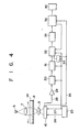
- Fig. 4 is a block diagram of the entire system according to an embodiment of the present invention. The mode of operation of the entire system will be described referring to Figs. 3 and 4.
- the code plate 8 mounted to a moving object 24 such as a table of a machine tool is illuminated by the light source 6 through the illumination lens 7, and an image of the pattern is formed on the line sensor 10 by the projection lens 9.
- the line sensor 10 starts scanning in response to a scanning start pulse 26 of a pulse generator 25, and also supplies output signals 28 to an amplifier 29 in synchronism with clock pulses 27 output from the pulse generator 25.
- the signals which have passed the amplifier 29 are supplied to a sample and hold circuit 30 which holds the peak value of the output of each element as an analog voltage which is converted into a digital signal by an analog to digital converter 31.
- a digital memory 32 sequentially stores the A/D converted outputs of the line sensor.
- the outputs of the line sensor are sequentially stored from the zero address of the memory by designating the addresses of the memory by the output of counter 33 which counts the block pulses output in synchronism with the outputs of the line sensor. In this manner, the addresses of the memory and the bit numbers of the line sensor may establish a one-to-one correspondence.
- the counter 33 must be reset in advance by the scanning start pulse 26 of the line sensor 10 or by a scanning terminating pulse 34.
- a signal processing circuit 36 comprises, for example, a microprocessor or the like. In response to the scanning terminating pulse 34 of the line sensor, the signal processing circuit 36 transfers the line sensor output data temporarily stored in the digital memory 32 to a data memory 35 under its control and starts processing the data.
- the operation of the signal processing circuit 36 includes the following:
- This output is displayed at a display 40 as a position relative to the direction of displacement and the direction perpendicular thereto.
- Fig. 8 shows an example of a circuit for reading with high precision the positions of the reference track or the fine reading patterns projected on the line sensor.
- a sample and hold circuit 41 is supplied with the output signals 28 of the line sensor to sample and hold them.
- the output of the sample and hold circuit 41 becomes as shown in Fig. 9(b).
- this output of the sample and hold circuit 41 is passed through a smoothing circuit 42, the signal as shown in Fig. 9(c) is obtained.
- the output of the smoothing circuit 42 is supplied to comparators 44 to 47, each having a different slicing level.
- an average value 58 obtained by the averaging circuit 57 represents the position of the reference track or the fine reading patterns projected on line sensor with sufficiently high precision. Since the counter circuits 49 to 52 are of the same circuit construction, the description will be made only with reference to the counter circuit 49.
- a latch circuit 55 latches the output of the counter 48 which is counting the output of the oscillator 43 from the scanning start point of the line sensor.
- the output of the counter 54 represents the length of the period in which the output of the comparator is "1". Therefore, when the output of the counter 54 is shifted by one bit to a lower significant bit, thus reducing the count of the counter 54 to half, and then is added by the adder 56 to the output of the latch circuit 55, the output of the adder 56 is obtained as the count of clock pulses of a frequency sufficiently higher than the frequency of the driving clock pulses for driving the line sensor to the central positions of the leading and trailing edges of the output of the comparator 44. With such measures, it is possible to detect the image formed on the line sensor with a resolution and a precision higher than the pitch of the photosensitive elements of the line sensor.
- the system described above may require a complex processing circuit but does not require high speed A/D conversion and allows real-time processing of the output signals of the line sensor so that an encoder which is less expensive and has a high response speed may be provided.
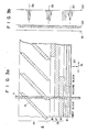
- Figs. 5 to 7 show, in simplified form, patterns of the code plate according to other embodiments of the present invention.
- the fine reading pattern of a fine reading track 14' comprises two patterns which are shifted, upon displacement of the code plate in the direction of-normal displacement, in opposite directions along the direction perpendicular thereto.
- fine readings may be obtained by measuring this change. That is to say, fine readings may be obtained even in the absence of a reference pattern.
- Reference numeral 13' denotes an address track.
- Fig. 6 shows an embodiment wherein two address tracks 17' and 18' are incorporated and an address track designating track 16' is also incorporated for designating which one of these address tracks is to be read.
- the fine reading pattern represented by a thick solid line corresponds to the address track 18'
- the fine reading pattern represented by a thin solid line corresponds to the address track 17', these fine reading patterns being within the range of one block of the address track.
- the line sensor when the line sensor is at position 11, reading is performed with the address track 18' and the corresponding fine reading pattern represented by the thick solid line according to a signal from the address track designating track 16'.
- the line sensor is at position 11', reading is performed in a similar manner with the address track 17' and the corresponding fine reading pattern represented by the thin solid line.
- fine reading tracks 14' and 14" each comprise triangular transmitting patterns.
- the fine reading track comprises a plurality of tracks as in the case of this embodiment, the fine reading patterns overlapping in the direction 19 of normal displacement may be distinguished so that only one kind of pattern may be required.
- which of the address tracks 17' and 18' is to be read is judged according to change of address with time. That is, if the result of the reading indicates an address different from that of the preceding reading of the address track 17', the reading will be performed next time with the address track 18' and the fine reading pattern of the corresponding fine reading track 14". If an address different from that of the preceding reading of the address track 18' is obtained, the reading will be performed next time with the address track 17' and the corresponding fine reading track 14'.
Landscapes
- Engineering & Computer Science (AREA)
- Theoretical Computer Science (AREA)
- Transmission And Conversion Of Sensor Element Output (AREA)
- Optical Transform (AREA)
Claims (10)
Applications Claiming Priority (2)
| Application Number | Priority Date | Filing Date | Title |
|---|---|---|---|
| JP8169980A JPS576996A (en) | 1980-06-17 | 1980-06-17 | Absolute encoder |
| JP81699/80 | 1980-06-17 |
Publications (3)
| Publication Number | Publication Date |
|---|---|
| EP0042178A2 EP0042178A2 (de) | 1981-12-23 |
| EP0042178A3 EP0042178A3 (en) | 1983-06-29 |
| EP0042178B1 true EP0042178B1 (de) | 1986-05-14 |
Family
ID=13753618
Family Applications (1)
| Application Number | Title | Priority Date | Filing Date |
|---|---|---|---|
| EP81104659A Expired EP0042178B1 (de) | 1980-06-17 | 1981-06-16 | Absolutcodierer |
Country Status (4)
| Country | Link |
|---|---|
| US (1) | US4384204A (de) |
| EP (1) | EP0042178B1 (de) |
| JP (1) | JPS576996A (de) |
| DE (1) | DE3174617D1 (de) |
Families Citing this family (28)
| Publication number | Priority date | Publication date | Assignee | Title |
|---|---|---|---|---|
| US4546347A (en) * | 1981-05-18 | 1985-10-08 | Mouse Systems Corporation | Detector for electro-optical mouse |
| CH658514A5 (de) * | 1982-02-09 | 1986-11-14 | Wild Heerbrugg Ag | Verfahren und vorrichtung zur erfassung einer messgroesse. |
| US4526471A (en) * | 1982-06-17 | 1985-07-02 | Bykov Anatoly P | Method for sensing spatial coordinate of article point and apparatus therefor |
| DE3308813C2 (de) * | 1983-03-12 | 1985-02-07 | Dr. Johannes Heidenhain Gmbh, 8225 Traunreut | Meßeinrichtung |
| US4555625A (en) * | 1983-03-21 | 1985-11-26 | Rockwell International Corporation | Precision drum encoder |
| CH676043A5 (de) * | 1983-12-30 | 1990-11-30 | Wild Leitz Ag | |
| US4680466A (en) * | 1984-04-20 | 1987-07-14 | Yokogawa Hokushin Electric Corporation | Displacement transducer which simultaneously extracts signals via sequential switching |
| US4633224A (en) * | 1985-05-06 | 1986-12-30 | Caterpillar Inc. | Absolute and incremental optical encoder |
| ATE51445T1 (de) * | 1986-02-07 | 1990-04-15 | Saphirwerk Ind Prod | Vorrichtung zur inkrementalen laengenmessung. |
| SE460928B (sv) * | 1986-10-13 | 1989-12-04 | Johansson Ab C E | Absolutmaetande skalsystem |
| DE3737278A1 (de) * | 1986-11-04 | 1988-05-11 | Canon Kk | Verfahren und vorrichtung zum optischen erfassen der stellung eines objekts |
| US4899048A (en) * | 1987-04-27 | 1990-02-06 | Printware, Inc. | Focused optical beam encoder of position |
| JPS6441819A (en) * | 1987-08-07 | 1989-02-14 | Matsushita Electric Ind Co Ltd | Position detecting apparatus |
| JP2600235B2 (ja) * | 1987-12-28 | 1997-04-16 | 松下電器産業株式会社 | 位置検出装置 |
| JPH01255014A (ja) * | 1988-04-04 | 1989-10-11 | Mitsubishi Electric Corp | 位置検出回路 |
| US5214426A (en) * | 1988-07-12 | 1993-05-25 | Furuno Electric Company, Limited | Rotary encoder having absolute angle patterns and relative angle patterns |
| US4942621A (en) * | 1988-11-15 | 1990-07-17 | Msc Technologies, Inc. | Method for mapping scanned pixel data |
| US4984287A (en) * | 1988-11-15 | 1991-01-08 | Msc Technologies, Inc. | Method for orienting a dual mouse optical scanner |
| US5237391A (en) * | 1988-11-23 | 1993-08-17 | The Boeing Company | Multitrack multilevel sensing system |
| US5294793A (en) * | 1991-08-23 | 1994-03-15 | Rsf-Elektronik Gesellschaft M.B.H. | System for measuring lengths or angles with a high-velocity movable scanning unit |
| US5665974A (en) * | 1995-11-16 | 1997-09-09 | The Boeing Company | Self-monitoring optical encoder for wavelength division multiplexing optical sensors |
| GB9909654D0 (en) * | 1999-04-28 | 1999-06-23 | Smiths Industries Plc | Syringe pump |
| US7135673B2 (en) * | 2004-10-29 | 2006-11-14 | The Boeing Company | Imaging rotation angle absolute encoder |
| CN101586968B (zh) * | 2008-05-19 | 2011-03-09 | 台达电子工业股份有限公司 | 高解析绝对型编码装置及其操作方法 |
| US7547875B1 (en) * | 2008-05-29 | 2009-06-16 | Delta Electronics, Inc. | Absolute type encoder apparatus and method for operating the same |
| EP2163859A1 (de) * | 2008-09-12 | 2010-03-17 | Leica Geosystems AG | Verfahren und Vorrichtung zum Bestimmen von Positionen |
| JP5574899B2 (ja) * | 2010-09-24 | 2014-08-20 | キヤノン株式会社 | ロータリーエンコーダ及びこれを備えた光学機器 |
| JP6000759B2 (ja) * | 2012-08-31 | 2016-10-05 | キヤノン株式会社 | スケール、エンコーダ、レンズ装置、および、撮像システム |
Family Cites Families (5)
| Publication number | Priority date | Publication date | Assignee | Title |
|---|---|---|---|---|
| US3270567A (en) * | 1961-09-11 | 1966-09-06 | Honeywell Inc | Control apparatus |
| US3410976A (en) * | 1965-06-09 | 1968-11-12 | Itek Corp | Shaft angle encoder with phase detection |
| FR1513177A (fr) * | 1967-03-07 | 1968-02-09 | Exaprecis | Galvanomètre numérique |
| FR2214389A5 (de) * | 1973-01-17 | 1974-08-09 | Sodern | |
| JPS5526469A (en) * | 1978-08-15 | 1980-02-25 | Matsushita Electric Ind Co Ltd | Encoder unit |
-
1980
- 1980-06-17 JP JP8169980A patent/JPS576996A/ja active Pending
-
1981
- 1981-06-10 US US06/272,265 patent/US4384204A/en not_active Expired - Lifetime
- 1981-06-16 EP EP81104659A patent/EP0042178B1/de not_active Expired
- 1981-06-16 DE DE8181104659T patent/DE3174617D1/de not_active Expired
Also Published As
| Publication number | Publication date |
|---|---|
| EP0042178A3 (en) | 1983-06-29 |
| DE3174617D1 (en) | 1986-06-19 |
| US4384204A (en) | 1983-05-17 |
| EP0042178A2 (de) | 1981-12-23 |
| JPS576996A (en) | 1982-01-13 |
Similar Documents
| Publication | Publication Date | Title |
|---|---|---|
| EP0042178B1 (de) | Absolutcodierer | |
| EP0042179B1 (de) | Codierer | |
| US4518859A (en) | Angle measuring device with line sensor | |
| US4421980A (en) | Position encoder with closed-ring diode array | |
| EP0503716B1 (de) | Messanordnung zur Bestimmung einer absoluten Position eines bewegbaren Elements und Skalenteilungselement zur Verwendung in einer derartigen Messanordnung | |
| US5235181A (en) | Absolute position detector for an apparatus for measuring linear angular values | |
| EP0039082B1 (de) | Verfahren und Einrichtung zum Messen der Verschiebung zwischen einer Kodierplatte und einer Sensoranordnung | |
| US4701615A (en) | Measuring scale coding system for length or angle measuring instruments | |
| US4654527A (en) | Reference mark identification system for measuring instrument | |
| US4794251A (en) | Apparatus for measuring lengths or angles | |
| JPH0445764B2 (de) | ||
| US5825307A (en) | Absolute linear encoder and method of production utilizing index and counter channels | |
| JPH09229717A (ja) | 位置測定装置 | |
| US5294793A (en) | System for measuring lengths or angles with a high-velocity movable scanning unit | |
| JPH0157292B2 (de) | ||
| EP2878928B1 (de) | Absolutcodierer, Signalverarbeitungsverfahren, Programm, Ansteuerungsvorrichtung und Industriemaschine | |
| EP0039921B1 (de) | Codiergerät und Verfahren zu seiner Verwendung | |
| WO2007057645A1 (en) | Scale and readhead apparatus and method | |
| JPH09145408A (ja) | エンコーダ装置 | |
| US5456021A (en) | Apparatus and method for measuring linear and angular displacements | |
| JP3503033B2 (ja) | 光学的変位量測定装置 | |
| US3529170A (en) | Apparatus for signalling the instantaneous position of an object movable along a predetermined path | |
| JPH05196451A (ja) | 測長または測角装置 | |
| JP2697159B2 (ja) | 絶対位置検出装置 | |
| JPH0157291B2 (de) |
Legal Events
| Date | Code | Title | Description |
|---|---|---|---|
| PUAI | Public reference made under article 153(3) epc to a published international application that has entered the european phase |
Free format text: ORIGINAL CODE: 0009012 |
|
| 17P | Request for examination filed |
Effective date: 19810716 |
|
| AK | Designated contracting states |
Designated state(s): CH DE FR GB SE |
|
| PUAL | Search report despatched |
Free format text: ORIGINAL CODE: 0009013 |
|
| AK | Designated contracting states |
Designated state(s): CH DE FR GB LI SE |
|
| GRAA | (expected) grant |
Free format text: ORIGINAL CODE: 0009210 |
|
| AK | Designated contracting states |
Kind code of ref document: B1 Designated state(s): CH DE FR GB LI SE |
|
| REF | Corresponds to: |
Ref document number: 3174617 Country of ref document: DE Date of ref document: 19860619 |
|
| ET | Fr: translation filed | ||
| PLBE | No opposition filed within time limit |
Free format text: ORIGINAL CODE: 0009261 |
|
| STAA | Information on the status of an ep patent application or granted ep patent |
Free format text: STATUS: NO OPPOSITION FILED WITHIN TIME LIMIT |
|
| 26N | No opposition filed | ||
| REG | Reference to a national code |
Ref country code: CH Ref legal event code: PFA Free format text: KABUSHIKI KAISHA TOPCON |
|
| REG | Reference to a national code |
Ref country code: FR Ref legal event code: CD |
|
| PGFP | Annual fee paid to national office [announced via postgrant information from national office to epo] |
Ref country code: FR Payment date: 19920521 Year of fee payment: 12 |
|
| PGFP | Annual fee paid to national office [announced via postgrant information from national office to epo] |
Ref country code: GB Payment date: 19920605 Year of fee payment: 12 |
|
| PGFP | Annual fee paid to national office [announced via postgrant information from national office to epo] |
Ref country code: SE Payment date: 19920617 Year of fee payment: 12 |
|
| PG25 | Lapsed in a contracting state [announced via postgrant information from national office to epo] |
Ref country code: GB Effective date: 19930616 |
|
| PG25 | Lapsed in a contracting state [announced via postgrant information from national office to epo] |
Ref country code: SE Effective date: 19930617 |
|
| GBPC | Gb: european patent ceased through non-payment of renewal fee |
Effective date: 19930616 |
|
| PG25 | Lapsed in a contracting state [announced via postgrant information from national office to epo] |
Ref country code: FR Effective date: 19940228 |
|
| REG | Reference to a national code |
Ref country code: FR Ref legal event code: ST |
|
| EUG | Se: european patent has lapsed |
Ref document number: 81104659.8 Effective date: 19940110 |
|
| PGFP | Annual fee paid to national office [announced via postgrant information from national office to epo] |
Ref country code: CH Payment date: 20000518 Year of fee payment: 20 |
|
| PGFP | Annual fee paid to national office [announced via postgrant information from national office to epo] |
Ref country code: DE Payment date: 20000726 Year of fee payment: 20 |
|
| PG25 | Lapsed in a contracting state [announced via postgrant information from national office to epo] |
Ref country code: LI Free format text: LAPSE BECAUSE OF EXPIRATION OF PROTECTION Effective date: 20010615 Ref country code: CH Free format text: LAPSE BECAUSE OF EXPIRATION OF PROTECTION Effective date: 20010615 |
|
| REG | Reference to a national code |
Ref country code: CH Ref legal event code: PL |