EP0041802A1 - Fluidumverdrängungsanlagen mit Exzenterschneckenelementen - Google Patents
Fluidumverdrängungsanlagen mit Exzenterschneckenelementen Download PDFInfo
- Publication number
- EP0041802A1 EP0041802A1 EP81302384A EP81302384A EP0041802A1 EP 0041802 A1 EP0041802 A1 EP 0041802A1 EP 81302384 A EP81302384 A EP 81302384A EP 81302384 A EP81302384 A EP 81302384A EP 0041802 A1 EP0041802 A1 EP 0041802A1
- Authority
- EP
- European Patent Office
- Prior art keywords
- seal element
- scroll
- fluid
- spiral
- end plate
- Prior art date
- Legal status (The legal status is an assumption and is not a legal conclusion. Google has not performed a legal analysis and makes no representation as to the accuracy of the status listed.)
- Granted
Links
- 239000012530 fluid Substances 0.000 title claims abstract description 75
- 238000006073 displacement reaction Methods 0.000 title claims abstract description 12
- 238000007789 sealing Methods 0.000 claims abstract description 29
- 230000002787 reinforcement Effects 0.000 claims abstract description 13
- 229920001343 polytetrafluoroethylene Polymers 0.000 claims description 8
- 239000004810 polytetrafluoroethylene Substances 0.000 claims description 8
- 229910000831 Steel Inorganic materials 0.000 claims description 7
- 239000010959 steel Substances 0.000 claims description 7
- 239000004033 plastic Substances 0.000 claims description 6
- 230000008859 change Effects 0.000 claims description 5
- 230000000694 effects Effects 0.000 claims description 4
- 238000007373 indentation Methods 0.000 claims description 4
- 238000005452 bending Methods 0.000 abstract description 8
- 230000006835 compression Effects 0.000 abstract description 4
- 238000007906 compression Methods 0.000 abstract description 4
- 230000007246 mechanism Effects 0.000 description 8
- 238000010276 construction Methods 0.000 description 6
- 239000000463 material Substances 0.000 description 5
- 239000011796 hollow space material Substances 0.000 description 4
- 238000004519 manufacturing process Methods 0.000 description 3
- 239000011347 resin Substances 0.000 description 3
- 229920005989 resin Polymers 0.000 description 3
- 238000007667 floating Methods 0.000 description 2
- 239000002184 metal Substances 0.000 description 2
- 238000000034 method Methods 0.000 description 2
- 239000003507 refrigerant Substances 0.000 description 2
- 210000002105 tongue Anatomy 0.000 description 2
- 239000002131 composite material Substances 0.000 description 1
- 238000001816 cooling Methods 0.000 description 1
- 230000007423 decrease Effects 0.000 description 1
- 230000001419 dependent effect Effects 0.000 description 1
- ZZUFCTLCJUWOSV-UHFFFAOYSA-N furosemide Chemical compound C1=C(Cl)C(S(=O)(=O)N)=CC(C(O)=O)=C1NCC1=CC=CO1 ZZUFCTLCJUWOSV-UHFFFAOYSA-N 0.000 description 1
- 230000004048 modification Effects 0.000 description 1
- 238000012986 modification Methods 0.000 description 1
- 238000005192 partition Methods 0.000 description 1
- 230000002093 peripheral effect Effects 0.000 description 1
- -1 polytetrafluoroethylene Polymers 0.000 description 1
- 230000008569 process Effects 0.000 description 1
- 230000009467 reduction Effects 0.000 description 1
- 230000000717 retained effect Effects 0.000 description 1
Images


Classifications
-
- F—MECHANICAL ENGINEERING; LIGHTING; HEATING; WEAPONS; BLASTING
- F01—MACHINES OR ENGINES IN GENERAL; ENGINE PLANTS IN GENERAL; STEAM ENGINES
- F01C—ROTARY-PISTON OR OSCILLATING-PISTON MACHINES OR ENGINES
- F01C19/00—Sealing arrangements in rotary-piston machines or engines
- F01C19/08—Axially-movable sealings for working fluids
-
- F—MECHANICAL ENGINEERING; LIGHTING; HEATING; WEAPONS; BLASTING
- F01—MACHINES OR ENGINES IN GENERAL; ENGINE PLANTS IN GENERAL; STEAM ENGINES
- F01C—ROTARY-PISTON OR OSCILLATING-PISTON MACHINES OR ENGINES
- F01C1/00—Rotary-piston machines or engines
- F01C1/02—Rotary-piston machines or engines of arcuate-engagement type, i.e. with circular translatory movement of co-operating members, each member having the same number of teeth or tooth-equivalents
- F01C1/0207—Rotary-piston machines or engines of arcuate-engagement type, i.e. with circular translatory movement of co-operating members, each member having the same number of teeth or tooth-equivalents both members having co-operating elements in spiral form
- F01C1/0215—Rotary-piston machines or engines of arcuate-engagement type, i.e. with circular translatory movement of co-operating members, each member having the same number of teeth or tooth-equivalents both members having co-operating elements in spiral form where only one member is moving
Definitions
- This invention relates to a fluid displacement apparatus, and more particularly, to a fluid displacement apparatus of the scroll type.
- U.S. Patent No. 801,182 discloses a device including two scroll members each having a circular end plate and a spiroidal or involute spiral element. These scroll members are maintained angularly and radially offset so that both spiral elements interfit to make a plurality of line contacts between their spiral curved surfaces, thereby to seal off and define at least one pair of fluid pockets.
- the relative orbital motion of the two scroll members shifts the line contact along the spiral curved surfaces and, therefore, the fluid pockets change in volume.
- the volume of the fluid pockets increases or decreases dependent on the direction of the orbiting motion. Therefore, the scroll type apparatus is applicable to compress, expand or pump fluids.
- the scroll type compressor In comparison with conventional compressors of the piston type, the scroll type compressor has certain advantages, such as fewer parts and continuous compression of fluid.
- the sealing of the fluid pockets primarily the sealing of the fluid pockets. Sealing of the fluid pockets must be sufficiently maintained in a scroll type fluid displacement apparatus, because the fluid pockets are defined by the line contacts between the interfitting spiral elements and axial contacts between the axial end surfaces of the spiral elements and the inner surfaces of the end plates.
- the pressure of the high pressure fluid introduced must be increased, and the clearance between radial supporting parts must be made as small as possible.
- costly close tolerances of the working parts is required to minimize this clearance, while- an increase of the pressure of the introduced fluid results in increased contact pressure between both scroll members, which increases mechanical loss or may damage them.
- Another method for improving the axial seal of the fluid pockets is to use seal elements which are mounted in the axial end surface of each of the spiral elements, as disclosed in U.S. Patent No. 3,994,635.
- the end surface of each spiral element facing the wend plate of the other scroll member is provided with a groove formed along the spiral
- a seal element is placed within each of the grooves.
- An axial force urging means in each groove such as a spring, urges the seal toward the facing end surface of the end plate to thereby effect axial sealing.
- the construction for the axial force urging means for the seal is complex, and it is difficult to obtain the desired uniform-sealing force along the length of the seal element.
- the seal element is loosely fitted into the groove formed in the axial end surface of each spiral element, and the pressurized fluid is introduced into the groove from adjacent fluid pockets to urge the seal element towards the facing end plate, as a substitute for mechanical urging means, to thereby effect axial sealing.
- the seal element is subject to localized excessive wear during a portion of the orbital motion of the orbiting scroll member. That is, during the period when the pair of fluid pockets are both connected to the central high pressure space, localized fluid pressure behind the seal element is suddenly enlarged, resulting in excessive sealing force which sometimes induces localized bending of the seal element and excessive sealing force.
- the apparatus should have a simple construction, a simple production method, and low cost.
- a scroll type fluid displacement apparatus includes a pair of scroll members each comprising an end plate and a spiral wrap means extending from one surface of said end plate and provided with a groove which is formed in the axial end surface thereof along the spiral curve, both wrap means interfitting at an angular offset to make a plurality of line contacts to define at least one pair of sealed off fluid pockets, drive means operatively connected to one of said scroll members to cause said one scroll member to undergo orbital motion relative to the other scroll member, and prevent rotation of said one scroll member, whereby said fluid pockets change volume by the orbital motion of said one scroll member, and a seal element disposed within said groove of said wrap means, wherein a reinforcement member supports said seal element for rigidifying said seal element.
- One embodiment of the invention is scroll type fluid displacement apparatus which includes a pair of scroll members each comprising an end plate and a spiral wrap means extending from one side of the end plate.
- the spiral is provided with a groove which is formed in the axial end surface thereof and extends along the spiral curve of the wrap means.
- a seal element is loosely fitted in the groove, and has a reinforcement member for preventing the localized bending thereof.
- the pressurized fluid flows from adjacent fluid pockets which are formed between the interfitting scroll members into the groove to urge the seal element into contact with the opposite end plate means, without localized bending thereof.
- the seal element comprises a sliding member and a core member for the reinforcement member.
- the core member is formed of a metal having a high rigidity, such as steel, and the sliding - member is formed of a material which has a high sealing efficiency with low friction coefficient, such as polytetrafluoroethylene (PTFE) resin.
- PTFE polytetrafluoroethylene
- the seal element may be disposed within a channel-shaped guide member.
- the axial end surface of the seal element extends from the opening portion of the guide member. Therefore, sufficient rigidity of the seal element is afforded by the guide member. Integral springy protrusions formed on the bottom wall of the guide member urge the seal element into sealing engagement with the end plate.
- a preferred embodiment of the invention is a fluid displacement apparatus of the compressor type, other types of fluid displacement apparatus are also included within the scope of the invention.
- the scroll type compressor unit operates by moving sealed off fluid pockets from a low pressure region to a high pressure region.
- Figs. 1a - ld may be considered to be end views of a compressor wherein the end plates are removed and only spiral elements are shown.
- Two spiral elements 1 and 2 are angularly offset and interfit with one another.
- the orbiting spiral element 1 and fixed spiral element 2 make four line contacts due to the radial offset of one spiral as shown at four points A-D.
- a pair of fluid pockets 3a' and 3b are defined between line contacts D, C and line contacts A, B, as shown by the dotted regions.
- the fluid pockets 3a and 3b are defined not only by the walls of spiral elements 1 and 2, but also by the end plates from which these spiral elements extend.
- both pockets 3a and 3b merge at the central portion 5 and are completely connected to one another to form a single pocket.
- the volume of the connected single pocket is further reduced by further revolutions of 90° as shown in Figs. lb, le and Id, and is substantially zero in status of Fig. ld.
- outer spaces which open in the state shown in Fig. lb change as shown in Figs. lc, ld and la to form new sealed off pockets in which fluid is newly enclosed.
- a seal element mounted in the axial end surface of each spiral element is urged towards the end plate by the pressure differential across the end surface of the spiral wrap to insure axial sealing.
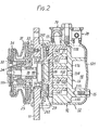
- a compressor such as a refrigerant compressor, which includes a compressor housing 10 comprising- a front end plate 11 and a cup-shaped casing 12 disposed on the end surface of the front end plate ll.
- a fixed scroll member 13, an orbiting scroll member 14, and driving mechanism and a rotation preventing/thrust bearing mechanism of orbiting scroll member 14 are disposed within an inner chamber of cup-shaped casing 12 which is. formed between inner wall of cup-shaped casing 12 and end surface of front end plate 11.
- Fixed scroll member 13 includes a circular end plate 131, a wrap or spiral element 132 affixed to or extending from one side surface of circular plate 131, and a plurality of internally threaded bosses 133 axially projecting from the end surface of plate 131 opposite to the side thereof from which spiral element 132 extends.
- the end surface of each boss 132 is seated on the inner surface of end plate portion 121 of cup-shaped casing 12 and is fixed to end plate portion 121 by a bolt 15.
- fixed scroll member 13 is fixedly disposed within cup-shaped casing 12.
- Circular plate 131 of fixed scroll member 13 partitions the inner chamber of cup-shaped casing 12 into discharge chamber 16 and suction chamber 17 by a seal ring 134 disposed between the outer peripheral surface of circular plate 131 and the inner wall of cup-shaped casing 12.
- Orbiting scroll member 14 is disposed in sunction chamber 17 of the casing 12 and also comprises a circular end plate 141 and a wrap means or spiral element 142 affixed or extending from one side surface of circular plate 141. Spiral element 142 and spiral element 132 of fixed scroll member 13 interfit at angular offset of 180° and predetermined radial offset; therefore, a pair of fluid pockets are defined between spiral elements 132, 142. Orbiting scroll member 14 is connected to the driving mechanism and to the rotation preventing/thrust bearing mechanism. These last two mechanisms effect orbital motion at circular radius Ro by rotation of drive shaft 18, which is rotatably supported by front end plate ll, to thereby compress the fluid, as described in connection with Fig. 1.
- Drive shaft 18 is rotatably supported by a sleeve portion 111 of front end plate ll, which projects from the front surface of front end plate ll, through a bearing 24.
- Drive shaft 18 has a disk portion 181 at its inner end portion.
- Disk portion 181 is also rotatably supported by front end plate 11 through a bearing 25 which is disposed within an opening of front end plate ll.
- a crank pin or drive pin 182 axially projects from an end surface of disk portion 181 and is radially offset from the center of drive shaft 18.
- Circular plate 141 of orbiting scroll member 14 is provided with a tubular boss 143 axially projecting from an end surface opposite to the side thereof from which spiral element 142 extends.
- a discoid or short axial bushing 26 is fitted into boss 143 and is rotatably supported therein by a bearing means, such as a needle bearing 27.
- Bushing 26 has a balance weight 261 which is shaped as a portion of a disc or ring and extends radially from bushing 26 along a front surface thereof.
- An eccentric hole 262 is formed in bushing 26, radially offset from the center of bushing 26.
- Drive pin 182 is fitted into the eccentrically disposed hole 262 within which a bearing 28 may be applied.
- Bushing -26 is therefore driven by the revolution of drive pin 182 and permitted to rotate by needle bearing 27.
- a pulley 31 is rotatably supported by a bearing 32.
- Bearing 32 is disposed on the outer surface of sleeve portion III.
- An electromagnetic annular coil 33 is fixed to the outer surface of sleeve portion III and is received in an annular cavity of pulley 31.
- An armature plate 34 is elastically supported on the outer end of drive shaft 18 which extends from sleeve portion III.
- a magnetic clutch comprising pulley 31, magnetic coil 33 and armature plate 34 is thereby formed.
- drive shaft 18 is driven by an external drive power source, for example, a motor of a vehicle, through a rotation force transmitting means, such as the magnetic clutch.
- orbiting scroll member 14 is prevented by a rotation preventing/thrust bearing means 29 which is disposed between the inner surface of the housing 10 and circular plate 141 of the orbiting scroll member, whereby orbiting scroll member 14 orbits while maintaining its angular orientation relative to the fixed scroll member.
- Rotation preventing/thrust bearing means 29 is disposed to surround boss 143 and is comprised of a fixed ring 291 and a sliding ring 292.
- Fixed ring 291 is secured to an end surface of front end plate 11 by pins 293.
- Fixed ring 291 is provided with a ⁇ pair of keyways 291a, 291b in an axial end surface facing orbiting scroll member 14.
- Sliding ring 292 is disposed in a hollow space between fixed ring 291 and circular plate 141 of orbiting scroll member 14.
- Sliding ring 292 is provided with a pair of keys 292a, 292b on the surface facing fixed ring 291, which are received in keyways 291a, 291b. Therefore, sliding ring 292 is slidable in the radial direction by the guide of keys 292a, 292b within keyways 291a, 291b. Sliding ring 292 is also provided with a pair of keys .292e, 292d on its opposite surface. Keys 292c, 292d are arranged along a diameter perpendicular to the diameter along which keys 292a, 292b are arranged. Circular plate 141 of orbiting scroll member 14 is provided with a pair of keyways (in Fig.
- orbiting scroll member 14 is slidable in one radial direction with sliding ring 292, and is slidable in another radial direction independently.
- the .second direction is perpendicular to the first direction. Therefore, orbiting scroll member 14 is prevented from rotating, but is permitted to move in two radial directions perpendicular to one another.
- sliding ring 292 is provided with a plurality of pockets or holes 30 which are formed in an axial direction.
- a bearing means such as balls 31, each having a diameter which is longer than the thickness of sliding ring 292, are retained in pockets 30. Balls 31 contact and roll on the surface of fixed ring 291 and circular plate 141. Therefore, the axial thrust load from orbiting scroll member 14 is supported on fixed ring 291 through bearing means 31.
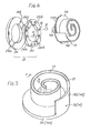
- each spiral element 132, 142 is provided with a groove 21 formed in its axial end surface along the spiral curve. Groove 21 extends from the inner end of the spiral element to a position close to the terminal end of the spiral element.
- a seal element 22 is loosely fitted within groove 21.
- a hollow space remains between the groove and the seal element adjacent the bottom surface of groove 21, as shown in Figs. 6-9.
- the hollow space is connected to adjacent fluid pockets which are formed between interfitting scroll members 13 and 14 by a gap between opposing circular -plates and the axial end surfaces of the spiral elements 132, 142 and a gap between seal element 22 and the side walls of groove 21. Therefore, during operation the compressed fluid flows from adjacent fluid pockets into the hollow space to urge seal element 22 into contact with the opposite circular plate so that a seal between the spiral elements and the circular plate is effected.
- Seal element 22 disposed within groove 21 is provided with a reinforcement member to prevent the localized bending of seal element 22.
- Seal element 22 comprises a sliding member 222 which is formed of a material having a high sealing efficiency with low friction coefficient, such as PTFE, having a contact surface adapted to engage the opposite circular plate and a core member 221 which is formed of a metal having a substantial rigidity, such as steel. Core member 221 is inserted near the center of sliding member 222, as shown in Fig. 6. Therefore, when the high local fluid pressure acts against seal element 22, localized bending of seal element 22 is prevented to thereby prevent localized wear of the seal element.
- sliding member 222 is affixed to the axial end surface of core member 221 so that the axial end surface of sliding member 222 contacts the opposite circular plate, as shown in-Fig. 7.
- seal element 22 the production of the seal element is very easy and inexpensive, because the seal element is obtained by the following process.
- the sliding member such as a plate of PTFE resin is affixed to the surface of a plate of material for the core member. These bonded plates are then cut together in a spiral configuration by a punch or the like, so that the seal element is easily obtained.
- two sliding members 222a and 222b are affixed to the opposite side surfaces of core member 21 so that the axial end surface of core member 221 is recessed from the plate contacting surfaces of sliding member 222a and 222b, as shown in Fig. 8.
- the production of the seal element is very easy and inexpensive.
- two concentric tubes of plastic material for the sliding member are bonded to the outer and inner -surfaces of a tube of steel for the core member.
- a cylindrical slice is cut from the composite tubular structure to form a ring.
- the exposed edge of the steel portion is etched to form a recess in the steel between the plastic portions.
- the ring is cut open so that it can be inserted into the spiral groove 21 in the spiral element.
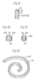
- Figs. 9-12 illustrate other embodiments of the seal element wherein the seal element has a guide member as the reinforcement member.
- Seal element 22 is formed of a material which has a high sealing efficiency with low friction coefficient, such as PTFE resin, and is disposed within a channel-shaped guide member 23. The axial end surface of seal element 22 projects from the opening portion of guide members 23.
- seal element 22 is formed with stepped portions or shoulders 221 near the axial end surface thereof (Figs. 9, 10), and the edges of the opening of guide member 23 are inwardly bent at 231 for engagement with shoulders 221 of seal element 22, as shown in Fig. 10. Therefore, seal element 22 is securely held within guide member 23 without axial movement.
- Fig. 11 shows another embodiment of a seal element holding construction wherein indentations 2 22 are formed along both side surfaces of seal element 22 and inward projections 232 are formed on both side walls of guide member 23 for engaging the indentations 222. Therefore, seal element 22 is securely held within guide member 23 without axial movement.
- the seal element 22 is held within guide member 23 without axial movement. Therefore, when the fluid pressure acting to seal element partly changes, the localized bending of seal element 22 is prevented thereby reducing localized wear on seal element 22.
- a plurality of projecting tongues are integrally formed or cut from the bottom portion of guide member 23, as shown in Fig. 12.
- the urging force acting to seal element 22 is in part due to the elasticity of tongues 233 and the fluid back pressure to thereby insure the axial sealing of the -fluid pockets.
- the width of the groove is made substantially the same as that of the seal element to leave no radial clearance for fluid to enter the space formed between the groove bottom and the seal element.
Landscapes
- Engineering & Computer Science (AREA)
- Mechanical Engineering (AREA)
- General Engineering & Computer Science (AREA)
- Rotary Pumps (AREA)
Applications Claiming Priority (4)
| Application Number | Priority Date | Filing Date | Title |
|---|---|---|---|
| JP74643/80U | 1980-05-31 | ||
| JP7464380U JPS5792U (de) | 1980-05-31 | 1980-05-31 | |
| JP115455/80U | 1980-08-13 | ||
| JP11545580U JPS5742186U (de) | 1980-08-13 | 1980-08-13 |
Publications (2)
| Publication Number | Publication Date |
|---|---|
| EP0041802A1 true EP0041802A1 (de) | 1981-12-16 |
| EP0041802B1 EP0041802B1 (de) | 1985-03-27 |
Family
ID=26415814
Family Applications (1)
| Application Number | Title | Priority Date | Filing Date |
|---|---|---|---|
| EP81302384A Expired EP0041802B1 (de) | 1980-05-31 | 1981-05-29 | Fluidumverdrängungsanlagen mit Exzenterschneckenelementen |
Country Status (5)
| Country | Link |
|---|---|
| US (1) | US4453899A (de) |
| EP (1) | EP0041802B1 (de) |
| AU (1) | AU547490B2 (de) |
| CA (1) | CA1221949A (de) |
| DE (1) | DE3169516D1 (de) |
Cited By (4)
| Publication number | Priority date | Publication date | Assignee | Title |
|---|---|---|---|---|
| US6958329B2 (en) | 2000-06-01 | 2005-10-25 | Bristol-Myers Squibb Pharma Company | Lactams substituted by cyclic succinates as inhibitors of A-β protein production |
| WO2011018598A3 (en) * | 2009-08-14 | 2011-09-15 | Edwards Limited | Scroll pump |
| US9353746B2 (en) | 2009-08-14 | 2016-05-31 | Edwards Limited | Scroll pump |
| US9938975B2 (en) | 2011-03-29 | 2018-04-10 | Edwards Limited | Scroll compressor including seal with axial length that is greater than radial width |
Families Citing this family (19)
| Publication number | Priority date | Publication date | Assignee | Title |
|---|---|---|---|---|
| JPS60243301A (ja) * | 1984-05-18 | 1985-12-03 | Mitsubishi Electric Corp | スクロール流体機械及びその流体機械の組立て方法 |
| JPS6134379A (ja) * | 1984-07-25 | 1986-02-18 | Sanden Corp | スクロ−ル型圧縮機 |
| US4627799A (en) * | 1984-08-27 | 1986-12-09 | Sanden Corporation | Axial sealing mechanism for a scroll type fluid displacement apparatus |
| NL8601212A (nl) * | 1986-05-14 | 1987-12-01 | Angli Holding Bv | Elektrisch geisoleerde koppeling voor metalen pijpen. |
| JPS63110683U (de) * | 1987-01-10 | 1988-07-15 | ||
| JP3369786B2 (ja) * | 1995-04-19 | 2003-01-20 | サンデン株式会社 | スクロール型圧縮機 |
| US6126422A (en) * | 1997-10-24 | 2000-10-03 | American Standard Inc. | Tip seal for scroll type compressor and manufacturing method therefor |
| JP4074058B2 (ja) * | 1997-11-04 | 2008-04-09 | モノジェン,インコーポレイテッド | 流体試料と粒子物質を混合および流体試料から粒子物質を分離をする方法、およびその装置 |
| US6074185A (en) * | 1998-11-27 | 2000-06-13 | General Motors Corporation | Scroll compressor with improved tip seal |
| FR2816363B1 (fr) * | 2000-11-08 | 2003-01-17 | Jean Claude Devoir | Etancheite et refroidissement des moteurs rotatifs et thermiques |
| JP2002180980A (ja) | 2000-12-08 | 2002-06-26 | Sanden Corp | スクロール型圧縮機 |
| US7228710B2 (en) * | 2005-05-31 | 2007-06-12 | Scroll Technologies | Indentation to optimize vapor injection through ports extending through scroll wrap |
| JP2007231796A (ja) * | 2006-02-28 | 2007-09-13 | Anest Iwata Corp | スクロール流体機械におけるチップシール |
| US20100040499A1 (en) * | 2008-08-14 | 2010-02-18 | General Electric Company | Screw pump rotors and ring seals for screw pump rotors |
| DE102010025803B4 (de) * | 2010-07-01 | 2016-05-19 | Schaeffler Technologies AG & Co. KG | Dichtungsanordnung |
| WO2015111146A1 (ja) * | 2014-01-22 | 2015-07-30 | 三菱電機株式会社 | スクロール圧縮機 |
| FR3047775B1 (fr) * | 2016-02-16 | 2018-03-02 | Danfoss Commercial Compressors | Dispositif de compression a spirales ayant un dispositif d'etancheite, et un compresseur a spirales comportant un tel dispositif de compression a spirales |
| JP1574166S (de) * | 2016-08-31 | 2020-04-06 | ||
| EP4174285B1 (de) * | 2022-12-22 | 2024-10-23 | Pfeiffer Vacuum Technology AG | Spiralvakuumpumpe |
Citations (6)
| Publication number | Priority date | Publication date | Assignee | Title |
|---|---|---|---|---|
| GB967644A (en) * | 1960-12-16 | 1964-08-26 | Curtiss Wright Corp | Oil seal for rotary internal combustion engines, pumps, fluid motors and compressors |
| DE1246338B (de) * | 1963-10-02 | 1967-08-03 | Daimler Benz Ag | Radialdichtung fuer eine Rotationskolbenmaschine |
| FR2201740A5 (en) * | 1972-10-02 | 1974-04-26 | Ramsey Corp | Wankel engine side seal strips - have hard porous heat-resistant coating in groove on contacting face |
| FR2305587A1 (fr) * | 1975-03-24 | 1976-10-22 | Little Inc A | Machine volumetrique |
| US4106780A (en) * | 1977-10-26 | 1978-08-15 | Ingersoll-Rand Company | Seal carrier for rotary piston engine |
| US4199308A (en) * | 1978-10-02 | 1980-04-22 | Arthur D. Little, Inc. | Axial compliance/sealing means for improved radial sealing for scroll apparatus and scroll apparatus incorporating the same |
Family Cites Families (11)
| Publication number | Priority date | Publication date | Assignee | Title |
|---|---|---|---|---|
| US2807511A (en) * | 1953-05-11 | 1957-09-24 | Gen Motors Corp | Coated piston ring |
| US2887331A (en) * | 1956-10-10 | 1959-05-19 | Gen Motors Corp | Closure |
| DE1218822B (de) * | 1964-06-26 | 1966-06-08 | Goetzewerke | Radialdichtung fuer Rotationskolbenmaschinen |
| DE2402558A1 (de) * | 1974-01-19 | 1975-07-24 | Borsig Gmbh | Dichtsystem fuer rotationskolbenverdichter |
| US3994633A (en) * | 1975-03-24 | 1976-11-30 | Arthur D. Little, Inc. | Scroll apparatus with pressurizable fluid chamber for axial scroll bias |
| US3994635A (en) * | 1975-04-21 | 1976-11-30 | Arthur D. Little, Inc. | Scroll member and scroll-type apparatus incorporating the same |
| US3986799A (en) * | 1975-11-03 | 1976-10-19 | Arthur D. Little, Inc. | Fluid-cooled, scroll-type, positive fluid displacement apparatus |
| US4065279A (en) * | 1976-09-13 | 1977-12-27 | Arthur D. Little, Inc. | Scroll-type apparatus with hydrodynamic thrust bearing |
| DE2834393A1 (de) * | 1977-08-19 | 1979-03-01 | Hawker Siddeley Brackett | Dichtungsanordnung |
| DE2909157C2 (de) * | 1978-03-10 | 1984-05-30 | Kabushiki Kaisha Toyoda Jidoshokki Seisakusho, Kariya, Aichi | Rotationsverdichter |
| US4212472A (en) * | 1978-05-30 | 1980-07-15 | Nippondenso Co., Ltd. | Seal assembly for rotary heat-exchanger |
-
1981
- 1981-05-26 AU AU71030/81A patent/AU547490B2/en not_active Expired
- 1981-05-27 US US06/267,456 patent/US4453899A/en not_active Expired - Lifetime
- 1981-05-29 EP EP81302384A patent/EP0041802B1/de not_active Expired
- 1981-05-29 DE DE8181302384T patent/DE3169516D1/de not_active Expired
- 1981-06-01 CA CA000378765A patent/CA1221949A/en not_active Expired
Patent Citations (9)
| Publication number | Priority date | Publication date | Assignee | Title |
|---|---|---|---|---|
| GB967644A (en) * | 1960-12-16 | 1964-08-26 | Curtiss Wright Corp | Oil seal for rotary internal combustion engines, pumps, fluid motors and compressors |
| DE1246338B (de) * | 1963-10-02 | 1967-08-03 | Daimler Benz Ag | Radialdichtung fuer eine Rotationskolbenmaschine |
| FR2201740A5 (en) * | 1972-10-02 | 1974-04-26 | Ramsey Corp | Wankel engine side seal strips - have hard porous heat-resistant coating in groove on contacting face |
| AU6066573A (en) * | 1972-10-02 | 1975-03-27 | Ramsey Corp | Rotary engine side seals |
| FR2305587A1 (fr) * | 1975-03-24 | 1976-10-22 | Little Inc A | Machine volumetrique |
| US3994636A (en) * | 1975-03-24 | 1976-11-30 | Arthur D. Little, Inc. | Axial compliance means with radial sealing for scroll-type apparatus |
| US4106780A (en) * | 1977-10-26 | 1978-08-15 | Ingersoll-Rand Company | Seal carrier for rotary piston engine |
| US4199308A (en) * | 1978-10-02 | 1980-04-22 | Arthur D. Little, Inc. | Axial compliance/sealing means for improved radial sealing for scroll apparatus and scroll apparatus incorporating the same |
| FR2438180A1 (fr) * | 1978-10-02 | 1980-04-30 | Little Inc A | Dispositif d'etancheite capable de ceder axialement pour machines a volute, et machines a volute comprenant ledit dispositif |
Cited By (7)
| Publication number | Priority date | Publication date | Assignee | Title |
|---|---|---|---|---|
| US6958329B2 (en) | 2000-06-01 | 2005-10-25 | Bristol-Myers Squibb Pharma Company | Lactams substituted by cyclic succinates as inhibitors of A-β protein production |
| WO2011018598A3 (en) * | 2009-08-14 | 2011-09-15 | Edwards Limited | Scroll pump |
| GB2485101A (en) * | 2009-08-14 | 2012-05-02 | Charles Robert Clark | Scroll pump |
| GB2485101B (en) * | 2009-08-14 | 2015-10-14 | Charles Robert Clark | Scroll pump |
| US9353746B2 (en) | 2009-08-14 | 2016-05-31 | Edwards Limited | Scroll pump |
| US9353748B2 (en) | 2009-08-14 | 2016-05-31 | Edwards Limited | Scroll pump having tip seal containing engaging portions intermediate nonengaging portions that interface with a scroll base |
| US9938975B2 (en) | 2011-03-29 | 2018-04-10 | Edwards Limited | Scroll compressor including seal with axial length that is greater than radial width |
Also Published As
| Publication number | Publication date |
|---|---|
| US4453899A (en) | 1984-06-12 |
| AU7103081A (en) | 1981-12-10 |
| AU547490B2 (en) | 1985-10-24 |
| DE3169516D1 (en) | 1985-05-02 |
| CA1221949A (en) | 1987-05-19 |
| EP0041802B1 (de) | 1985-03-27 |
Similar Documents
| Publication | Publication Date | Title |
|---|---|---|
| EP0041802B1 (de) | Fluidumverdrängungsanlagen mit Exzenterschneckenelementen | |
| EP0049480B1 (de) | Fluidumverdichter mit Exzenterspiralelementen | |
| KR950001867B1 (ko) | 스크롤압축기 | |
| EP0009355B1 (de) | Kompressoren des Exzenterspiraltyps | |
| EP0227249B1 (de) | Axialdichtungsmechanismus für ein Fluidverdrängungsgerät der Spiralbauweise | |
| KR100749040B1 (ko) | 스크롤 압축기 | |
| US4395205A (en) | Mechanically actuated tip seals for scroll apparatus and scroll apparatus embodying the same | |
| EP0010402B1 (de) | Verbesserungen an Kompressoren des Exzenterspiraltyps | |
| EP0059925A1 (de) | Antriebsmittel für eine Fluidumverdrängungsanlage mit Exzenterspiralelementen | |
| EP0010930A1 (de) | Kompressoren des Exzenterspiraltyps | |
| KR100916554B1 (ko) | 올덤 커플링을 위한 클리어런스를 가진 스크롤 압축기 | |
| EP0118900A1 (de) | Schmierungseinrichtung für Verdrängermaschine mit ineinandergreifenden Spiralelementen | |
| EP0061698A1 (de) | Vorrichtung mit kreisendem Kolben zum Fördern von Fluiden, mit einer Einrichtung zum Verhindern der Rotation | |
| US4548555A (en) | Scroll type fluid displacement apparatus with nonuniform scroll height | |
| US20180163725A1 (en) | Eccentric Compensating Torsional Drive System | |
| KR930008348B1 (ko) | 스크롤 유체기계 | |
| US5779461A (en) | Scroll type fluid displacement apparatus having a control system of line contacts between spiral elements | |
| EP0069531B1 (de) | Kompressor vom Spiraltyp mit verbessertem Auslassmechismus | |
| EP0122722A1 (de) | Axialdichtung für eine Verdrängungsmaschine der Spiralbauart | |
| US4477239A (en) | Scroll type fluid displacement apparatus with offset wraps for reduced housing diameter | |
| US5738504A (en) | Rotation preventing device for orbiting member of fluid displacement apparatus | |
| EP0464683A1 (de) | Flüssigkeitsverdichter | |
| EP0012614A1 (de) | Verbesserungen an Fluidumkompressoren mit ineinandergreifenden Spiralvorsprüngen | |
| EP0065261B1 (de) | Axialdichtung für eine Spiralverdrängermaschine | |
| US5692887A (en) | Fixed vane rotary compressor |
Legal Events
| Date | Code | Title | Description |
|---|---|---|---|
| PUAI | Public reference made under article 153(3) epc to a published international application that has entered the european phase |
Free format text: ORIGINAL CODE: 0009012 |
|
| AK | Designated contracting states |
Designated state(s): DE FR GB IT SE |
|
| 17P | Request for examination filed |
Effective date: 19820602 |
|
| RAP1 | Party data changed (applicant data changed or rights of an application transferred) |
Owner name: SANDEN CORPORATION |
|
| ITF | It: translation for a ep patent filed | ||
| GRAA | (expected) grant |
Free format text: ORIGINAL CODE: 0009210 |
|
| AK | Designated contracting states |
Designated state(s): DE FR GB IT SE |
|
| REF | Corresponds to: |
Ref document number: 3169516 Country of ref document: DE Date of ref document: 19850502 |
|
| ET | Fr: translation filed | ||
| PLBE | No opposition filed within time limit |
Free format text: ORIGINAL CODE: 0009261 |
|
| STAA | Information on the status of an ep patent application or granted ep patent |
Free format text: STATUS: NO OPPOSITION FILED WITHIN TIME LIMIT |
|
| 26N | No opposition filed | ||
| ITTA | It: last paid annual fee | ||
| EAL | Se: european patent in force in sweden |
Ref document number: 81302384.3 |
|
| PGFP | Annual fee paid to national office [announced via postgrant information from national office to epo] |
Ref country code: SE Payment date: 20000504 Year of fee payment: 20 |
|
| PGFP | Annual fee paid to national office [announced via postgrant information from national office to epo] |
Ref country code: FR Payment date: 20000510 Year of fee payment: 20 |
|
| PGFP | Annual fee paid to national office [announced via postgrant information from national office to epo] |
Ref country code: GB Payment date: 20000524 Year of fee payment: 20 |
|
| PGFP | Annual fee paid to national office [announced via postgrant information from national office to epo] |
Ref country code: DE Payment date: 20000529 Year of fee payment: 20 |
|
| PG25 | Lapsed in a contracting state [announced via postgrant information from national office to epo] |
Ref country code: GB Free format text: LAPSE BECAUSE OF EXPIRATION OF PROTECTION Effective date: 20010528 |
|
| PG25 | Lapsed in a contracting state [announced via postgrant information from national office to epo] |
Ref country code: SE Free format text: THE PATENT HAS BEEN ANNULLED BY A DECISION OF A NATIONAL AUTHORITY Effective date: 20010530 |
|
| REG | Reference to a national code |
Ref country code: GB Ref legal event code: PE20 Effective date: 20010528 |
|
| EUG | Se: european patent has lapsed |
Ref document number: 81302384.3 |