EP0037754B1 - Dispositif pour corriger la position d'une plaque portée par un cylindre d'une machine d'impression - Google Patents
Dispositif pour corriger la position d'une plaque portée par un cylindre d'une machine d'impression Download PDFInfo
- Publication number
- EP0037754B1 EP0037754B1 EP19810400386 EP81400386A EP0037754B1 EP 0037754 B1 EP0037754 B1 EP 0037754B1 EP 19810400386 EP19810400386 EP 19810400386 EP 81400386 A EP81400386 A EP 81400386A EP 0037754 B1 EP0037754 B1 EP 0037754B1
- Authority
- EP
- European Patent Office
- Prior art keywords
- wedge
- cylinder
- plate
- slit
- chamber
- Prior art date
- Legal status (The legal status is an assumption and is not a legal conclusion. Google has not performed a legal analysis and makes no representation as to the accuracy of the status listed.)
- Expired
Links
- 238000007639 printing Methods 0.000 title claims description 7
- 230000000295 complement effect Effects 0.000 claims description 4
- 238000007645 offset printing Methods 0.000 claims description 3
- 230000000717 retained effect Effects 0.000 claims description 3
- 230000001154 acute effect Effects 0.000 claims description 2
- 229910000831 Steel Inorganic materials 0.000 description 1
- 230000000694 effects Effects 0.000 description 1
- 238000000034 method Methods 0.000 description 1
- 230000002093 peripheral effect Effects 0.000 description 1
- 238000007493 shaping process Methods 0.000 description 1
- 239000010959 steel Substances 0.000 description 1
Images


Classifications
-
- B—PERFORMING OPERATIONS; TRANSPORTING
- B41—PRINTING; LINING MACHINES; TYPEWRITERS; STAMPS
- B41F—PRINTING MACHINES OR PRESSES
- B41F27/00—Devices for attaching printing elements or formes to supports
- B41F27/12—Devices for attaching printing elements or formes to supports for attaching flexible printing formes
- B41F27/1218—Devices for attaching printing elements or formes to supports for attaching flexible printing formes comprising printing plate tensioning devices
- B41F27/125—Devices for attaching printing elements or formes to supports for attaching flexible printing formes comprising printing plate tensioning devices moving in the printing plate end on a curvilinear path, e.g. by winding on a roll
Definitions
- the plate to be reproduced is formed on a flexible plate itself wound on a plate cylinder.
- the quality of the printing requires that this plate, which developed flat fits into a rectangular reference frame, has a strictly cylindrical position on the plate cylinder. If the plate is angularly offset with respect to the plate, when the latter is normally wound on the cylinder, the plate is in a helical form; it is then necessary to carry out a "correction of the cross", that is to say to mount the plate in a slightly helical manner, with a pitch opposite to that of the helical shape of the plate, which restores the cylindricity of the latter.
- the invention proposes a device for correcting the crosswise shape of a plate mounted on a plate cylinder of a printing machine, in particular in offset, this cylinder comprising a longitudinal chamber internal opening radially on the periphery of the cylinder through a slot in which the folded ends of the plate can be tucked in, one of which is applied and retained around a bearing edge provided on one of the edges of the slot , while the other is engaged with retaining means associated with members which, inside the chamber, are provided to ensure the tensioning of the plate, characterized in that the support edge can be adjusted angularly by means of a rigid block of generally prismatic shape comprising a tapered part adjacent to said edge of the slot and two parallel faces engaged in sliding contact in a housing adjacent to the chamber, and in that at the m oins two threaded rods, spaced from each other, which are screwed in complementary nuts fixed in the cylinder body and whose geometric axis passes through the cylinder slot, are supported and
- the device proposed by the invention in addition to being relatively simple and inexpensive, makes it possible to give the cylinder slot a width which, by comparison with known solutions, is small, without requiring the presence of an insert on the cylinder working surface.
- an elastic blade which extends to the right of the access opening to the housing of the wedge by forming a pressure tab whose free edge, on the one hand is resiliently biased in a position of contact with a wedge-shaped edge cut in the body of the cylinder, on the other hand can be moved away from this position under the action of the tapered part of the wedge.
- this tapered portion exerts no pressure on the pressure tab
- the bearing edge of the folded end of the plate is formed by the line common to the corner edge and to the free edge. of the tongue, but that it is this free edge which defines the support edge, where the tapered part of the wedge has pushed the tongue towards the inside of the slot.
- the adjustment shim is shaped from a parallelepipedic block in which is formed at least one bevel defining the tapered part, which, in the longitudinal direction of the shim, is delimited by two transverse bosses whose end opposite to the edge of the bevel coincides with a stepped notch, which is formed in the corresponding edge of the shim, and comprises a wide part in which is fixed a flange comprising a bore through which passes one of the threaded control rods, whose head, trapped in a cavity delimited by the narrow and deep part of the niche, can be reached by an operating tool through a bore formed in the corresponding boss.
- each threaded rod and the barrel of this rod have, in the cavity of the boss and in the bore of the flange, a clearance which allows the adjustment shim to assume a tilted position, necessary for ensuring the correction. across the plate.
- the adjustment shim can be adjusted laterally in position by complementary means, comprising for example threaded studs tightened in contact with the end faces of the wedge.
- the plate cylinder 1 in which the invention is incorporated and which is intended to cooperate with a blanket of an offset printing machine, has been shown as a whole, but in an extremely schematic manner, only Figure 6.
- the cylinder 1 In the longitudinal sectional view of Figure 1 the cylinder 1 has been shown over half its length, it being understood that at least as regards the invention the other half-length is practically symmetrical with the first with respect to the transverse plane XX.
- This slot constitutes the radial outlet of an internal longitudinal chamber 11, of generally cylindrical shape, traversed along its length by a drum 12, also of generally cylindrical shape, in which is formed a notch 13 provided for receiving and retaining the terminal edge bent 14 of the folded end 8 of the plate 9.
- the drum 12 can be rotated about an axis YY, with respect to which the drum is eccentric.
- each of the ends of the drum is provided with a ring 16 provided for journalling, by means of a needle bearing 17, in a bore 18 of the cylindrical body 2, and on the other hand the central part of the drum comprises two smooth bearings 19 in each of which is engaged an axis 21 integral with a central core 22 supported on a ring sector 23 and fixed by a screw 24 in the body of the cylinder.
- the drum 12 can be rotated by means of a hexagon head 26 which projects out of the ring 16.
- the drum is in fact in two parts arranged on either side of the median plane XX and assembled by means of a bolted joint 27.
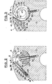
- a housing delimited by two parallel flat faces 29, 31 of which one, 29, forms with the adjacent surface 4 of the cylinder an acute angle corner whose point defines an edge 32 which practically merges with one of the edges of the slot 6 (fig. 3).
- the inlet opening 33 of the housing 28 is covered by an elastic tongue 34 whose free edge 36 is biased at contact of the edge 32 and which is part of an elastic blade 37 fixed, by means of a plate 38 and screws 39 driven into the body of the cylinder, on the internal surface of the chamber 31.
- This tongue 34 can be pushed back, against its own elasticity, by the tapered part 41 of an adjustment shim 42 inserted in the housing 28.
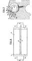
- This adjustment shim 42 shown in perspective in FIG. 5, has a generally prismatic shape resulting from the shaping of a parallelepipedal steel block in which two bevels 43 have been formed, defining the tapered part 41, are located on either side. 'other of the plane XX and which follow a flat face 44 in sliding contact with the face 31 of the housing 28.
- the face 46 of the wedge which is opposite the bevels 43, is a flat face in sliding contact with the face 29 housing 28.
- each bevel 43 is delimited by two bosses 47, 48, respectively central and terminal, each having two flat faces 54, 56, corresponding to the x flat faces 44, 46 and they also in sliding contact with the faces 31 and 29 of the housing 28.
- the end of the bosses 47, 48, which is opposite the edge 45 of the bevels 43, is set back with respect to the corresponding edge of the wedge, owing to the fact that this edge is cut out so as to form a stepped slot 57 or 58 which comprises a wide part 67 or 68 and a narrow and deeper part 77 or 78.
- a flange in T 87 which has in its center a bore 81 through which a threaded rod 82 screwed into a nut 83 embedded in the body of the cylinder, whose head 84 is contained and trapped in the cavity formed by the narrow part 77 of the slot 57.
- a through a bore 86 formed in the boss 47 it is possible to introduce, from the slot 6, a tool, such as a wrench, for tightening or loosening the threaded rod 82, the head of which is preferably hexagonally formed.
- a flange 88 in the form of a square, can be fixed in the wide part 68 of the terminal slot 58 to retain in the corresponding cavity 78 the head 84 of another threaded rod 82.
- the folded end 7 of the plate 9 must obviously have a cutout in line with each of the bosses 47, 48 which, as shown in FIG. 2, penetrate inside the chamber 11.
- FIGS. 6 and 7 represent a plate 9, the end 7 of which has been displaced by the quantity a on the edge A of the plate, while on the edge B the end 7 of the corresponding zone of the wedge 42 is sufficiently retracted into the housing 28 so that the tapered part 41 exerts no action on the tongue 34, the free edge 36 of which coincides consequently with the edge 32 of the cylinder body, in a position which corresponds to the figure 3.
- the shim 42 can be adjusted laterally in the appropriate adjustment position by means of threaded studs 89 screwed through the cylinder body 2, the end of which is tightened in abutment against the corresponding end section 50 of the wedge, and immobilized by a lock nut 90.
Landscapes
- Supply, Installation And Extraction Of Printed Sheets Or Plates (AREA)
Applications Claiming Priority (2)
| Application Number | Priority Date | Filing Date | Title |
|---|---|---|---|
| FR8006317A FR2478538A1 (fr) | 1980-03-21 | 1980-03-21 | Dispositif pour corriger la position d'une plaque portee par un cylindre d'une machine d'impression |
| FR8006317 | 1980-03-21 |
Publications (2)
| Publication Number | Publication Date |
|---|---|
| EP0037754A1 EP0037754A1 (fr) | 1981-10-14 |
| EP0037754B1 true EP0037754B1 (fr) | 1983-06-22 |
Family
ID=9239935
Family Applications (1)
| Application Number | Title | Priority Date | Filing Date |
|---|---|---|---|
| EP19810400386 Expired EP0037754B1 (fr) | 1980-03-21 | 1981-03-13 | Dispositif pour corriger la position d'une plaque portée par un cylindre d'une machine d'impression |
Country Status (3)
| Country | Link |
|---|---|
| EP (1) | EP0037754B1 (enExample) |
| DE (1) | DE3160458D1 (enExample) |
| FR (1) | FR2478538A1 (enExample) |
Families Citing this family (3)
| Publication number | Priority date | Publication date | Assignee | Title |
|---|---|---|---|---|
| US4870901A (en) * | 1988-05-06 | 1989-10-03 | W. R. Grace & Co.-Conn. | Apparatus for attaching a printing blanket to a printing cylinder |
| DE4005093C1 (en) * | 1990-02-17 | 1991-06-20 | Man Roland Druckmaschinen Ag, 6050 Offenbach, De | Forme clamp for printing cylinder - has channel in cylinder with spindle to clamp form eccentrically |
| US5419248A (en) * | 1994-03-09 | 1995-05-30 | Heidelberg Druckmaschinen Ag | Adjustable alignment device for printing plates |
Family Cites Families (6)
| Publication number | Priority date | Publication date | Assignee | Title |
|---|---|---|---|---|
| GB635628A (en) * | 1946-05-20 | 1950-04-12 | R Hoe & Crabtree Ltd | Improvements in plate straining mechanism for use in printing machines |
| FR1223614A (fr) * | 1959-01-30 | 1960-06-17 | Marinoni | Dispositif de mise en tension de plaques d'impression sur le cylindre de machines àimprimer rotatives |
| FR1283031A (fr) * | 1961-03-07 | 1962-01-27 | Miehle Goss Dexter Inc | Mécanisme pour fixer sous tension des plaques d'impression minces |
| FR1523531A (fr) * | 1967-04-07 | 1968-05-03 | Adamovske Strojirny Np | Installation pour le montage et le réglage de plaques stéréotypes flexibles sur machines à imprimer ainsi que machine pourvue de ladite installation |
| DE1945535B2 (de) * | 1969-09-09 | 1970-12-03 | Maschf Augsburg Nuernberg Ag | Vorrichtung zur Umfangsverschiebung biegsamer Druckplatten auf dem Formzylinder von Rotationsdruckmaschinen |
| DE2547481C3 (de) * | 1975-10-23 | 1983-12-15 | M.A.N. Maschinenfabrik Augsburg-Nürnberg AG, 8900 Augsburg | Vorrichtung zum Befestigen und Spannen von biegsamen Druckplatten |
-
1980
- 1980-03-21 FR FR8006317A patent/FR2478538A1/fr active Granted
-
1981
- 1981-03-13 EP EP19810400386 patent/EP0037754B1/fr not_active Expired
- 1981-03-13 DE DE8181400386T patent/DE3160458D1/de not_active Expired
Also Published As
| Publication number | Publication date |
|---|---|
| FR2478538A1 (fr) | 1981-09-25 |
| FR2478538B1 (enExample) | 1983-10-07 |
| EP0037754A1 (fr) | 1981-10-14 |
| DE3160458D1 (en) | 1983-07-28 |
Similar Documents
| Publication | Publication Date | Title |
|---|---|---|
| EP0334913B1 (fr) | Machine a chanfreiner perfectionnee | |
| EP0115724B1 (fr) | Dispositif de bridage notamment pour la fixation de pièces sur une machine-outil | |
| EP0384161B1 (fr) | Dispositif de fixation d'une forme d'usinage sur un cylindre porte-outil dans une machine rotative | |
| EP0037754B1 (fr) | Dispositif pour corriger la position d'une plaque portée par un cylindre d'une machine d'impression | |
| WO2004028236A2 (fr) | Dispositif de fixation de lames a un arbre rotatif et machine agricole equipee d’un tel dispositif | |
| FR2464115A1 (fr) | Outil coupant, par exemple fraise pour rainures de clavettes ou outil de brochage | |
| FR2781017A1 (fr) | Dispositif de fixation pour un composant reglable et devant etre bloque par serrage | |
| EP0049796B1 (fr) | Outil pour usinage à cartouches porte-plaquettes interchangeables | |
| FR2795013A1 (fr) | Outil de centrage et de serrage | |
| EP0916488B1 (fr) | Système de sérigraphie automatique | |
| FR2513166A1 (fr) | Outil a main pour l'enlevement de matiere sur une piece, notamment pour l'ebavurage ou le cassage d'angles | |
| FR2602922A1 (fr) | Outil pour decouper un revetement externe d'un cable, notamment un cable electrique | |
| EP0234171B1 (fr) | Tête d'alésage | |
| EP0099275B1 (fr) | Dispositif de fixation de l'habillage d'un cylindre de machine d'impression | |
| FR2795988A1 (fr) | Dispositif de positionnement d'une plaque sur un cylindre a fixation magnetique | |
| EP0195727B1 (fr) | Encrier à segments doseurs réglés individuellement pour une imprimeuse | |
| FR2844743A1 (fr) | Ensemble comprenant une unite de blanchet et un cylindre a dispositif de fixation de blanchet, cylindre, unite de blanchet et presse offset correspondants | |
| EP0992316B1 (fr) | Dispositif manuel de correction du positionnement du corps d'une électro-broche par rapport à son support | |
| FR2724697A1 (fr) | Goupille elastique creuse | |
| FR2690367A1 (fr) | Dispositif de positionnement d'un outil ou d'une pièce sur une machine-outil. | |
| FR2803264A1 (fr) | Procede de montage d'ouvrant de vehicule automobile et dispositif intervenant dans ce montage | |
| FR2679302A1 (fr) | Ecrou elastique perfectionne. | |
| FR2707202A1 (fr) | Dispositif d'immobilisation pour cylindre de découpe rotatif. | |
| FR2746044A1 (fr) | Outil a plaquettes interchangeables affutables et procede d'affutage des plaquettes de coupe | |
| FR2460183A1 (fr) | Manchon perfectionne de fixation pour mandrins de rodage |
Legal Events
| Date | Code | Title | Description |
|---|---|---|---|
| PUAI | Public reference made under article 153(3) epc to a published international application that has entered the european phase |
Free format text: ORIGINAL CODE: 0009012 |
|
| 17P | Request for examination filed |
Effective date: 19810729 |
|
| AK | Designated contracting states |
Designated state(s): CH DE FR GB IT SE |
|
| ITF | It: translation for a ep patent filed | ||
| GRAA | (expected) grant |
Free format text: ORIGINAL CODE: 0009210 |
|
| AK | Designated contracting states |
Designated state(s): CH DE FR GB IT LI SE |
|
| REF | Corresponds to: |
Ref document number: 3160458 Country of ref document: DE Date of ref document: 19830728 |
|
| PGFP | Annual fee paid to national office [announced via postgrant information from national office to epo] |
Ref country code: DE Payment date: 19840312 Year of fee payment: 4 |
|
| PGFP | Annual fee paid to national office [announced via postgrant information from national office to epo] |
Ref country code: CH Payment date: 19840315 Year of fee payment: 4 |
|
| PGFP | Annual fee paid to national office [announced via postgrant information from national office to epo] |
Ref country code: FR Payment date: 19840316 Year of fee payment: 4 |
|
| PGFP | Annual fee paid to national office [announced via postgrant information from national office to epo] |
Ref country code: SE Payment date: 19840331 Year of fee payment: 4 |
|
| PLBE | No opposition filed within time limit |
Free format text: ORIGINAL CODE: 0009261 |
|
| STAA | Information on the status of an ep patent application or granted ep patent |
Free format text: STATUS: NO OPPOSITION FILED WITHIN TIME LIMIT |
|
| 26N | No opposition filed | ||
| PG25 | Lapsed in a contracting state [announced via postgrant information from national office to epo] |
Ref country code: SE Effective date: 19880314 |
|
| PG25 | Lapsed in a contracting state [announced via postgrant information from national office to epo] |
Ref country code: LI Effective date: 19880331 Ref country code: CH Effective date: 19880331 |
|
| PG25 | Lapsed in a contracting state [announced via postgrant information from national office to epo] |
Ref country code: GB Free format text: LAPSE BECAUSE OF NON-PAYMENT OF DUE FEES Effective date: 19881118 |
|
| GBPC | Gb: european patent ceased through non-payment of renewal fee | ||
| PG25 | Lapsed in a contracting state [announced via postgrant information from national office to epo] |
Ref country code: FR Free format text: LAPSE BECAUSE OF NON-PAYMENT OF DUE FEES Effective date: 19881130 |
|
| REG | Reference to a national code |
Ref country code: CH Ref legal event code: PL Ref country code: CH Ref legal event code: AUV |
|
| PG25 | Lapsed in a contracting state [announced via postgrant information from national office to epo] |
Ref country code: DE Effective date: 19881201 |
|
| REG | Reference to a national code |
Ref country code: FR Ref legal event code: ST |
|
| EUG | Se: european patent has lapsed |
Ref document number: 81400386.9 Effective date: 19881205 |