EP0037747B1 - Spray nozzle, especially for a fertilizer - Google Patents
Spray nozzle, especially for a fertilizer Download PDFInfo
- Publication number
- EP0037747B1 EP0037747B1 EP81400264A EP81400264A EP0037747B1 EP 0037747 B1 EP0037747 B1 EP 0037747B1 EP 81400264 A EP81400264 A EP 81400264A EP 81400264 A EP81400264 A EP 81400264A EP 0037747 B1 EP0037747 B1 EP 0037747B1
- Authority
- EP
- European Patent Office
- Prior art keywords
- nozzle
- liquid
- diameter
- chamber
- nozzle according
- Prior art date
- Legal status (The legal status is an assumption and is not a legal conclusion. Google has not performed a legal analysis and makes no representation as to the accuracy of the status listed.)
- Expired
Links
Images
Classifications
-
- B—PERFORMING OPERATIONS; TRANSPORTING
- B05—SPRAYING OR ATOMISING IN GENERAL; APPLYING FLUENT MATERIALS TO SURFACES, IN GENERAL
- B05B—SPRAYING APPARATUS; ATOMISING APPARATUS; NOZZLES
- B05B1/00—Nozzles, spray heads or other outlets, with or without auxiliary devices such as valves, heating means
- B05B1/14—Nozzles, spray heads or other outlets, with or without auxiliary devices such as valves, heating means with multiple outlet openings; with strainers in or outside the outlet opening
-
- B—PERFORMING OPERATIONS; TRANSPORTING
- B05—SPRAYING OR ATOMISING IN GENERAL; APPLYING FLUENT MATERIALS TO SURFACES, IN GENERAL
- B05B—SPRAYING APPARATUS; ATOMISING APPARATUS; NOZZLES
- B05B1/00—Nozzles, spray heads or other outlets, with or without auxiliary devices such as valves, heating means
Definitions
- these spraying devices consist of rods or booms, generally of metal, pierced with several holes and the size of which varies from one rod to another.
- liquid fertilizers for a given liquid fertilizer inlet pressure.
- Spray nozzles are also known in particular for agriculture, having the same drawbacks as those described above. These nozzles are for example described in patents US-A-4,128,206 and US-A-3,191,871.
- the nozzle 7b is fixed to the barrel 5 for example, using a nut such as 13 screwed onto a threaded outlet such as 15 secured to the barrel 5. Between the threaded outlet 15 and the spray nozzle 7b, can be placed a seal such as 17. This nozzle 7b comprises on each side a flat 19 allowing the orientation of the liquid fertilizer jets.
- This coupling ring is, of course, provided with an opening 39 so as to allow the introduction of liquid fertilizers into the nozzle.
- the calibrated pellet reference 27b can be placed in the chamber 23 of the body of the nozzle 21.
- This chamber 23 comprising on its walls a recess 41 creating a reduction in the diameter of the chamber 23, allows attachment to force of the patch 27b, the diameter of which is greater than the diameter of the chamber 23 defined after the recess 41.
- this recess 41 exists, which allows the farmer to adapt the spray nozzle 7b on the barrel 5 (FIG. 2) according to the diameter of the threaded outlet 15.
Abstract
Description
La présente invention concerne une buse de pulvérisation notamment pour engrais permettant de pulvériser des engrais liquides sous forme de grosses gouttes.The present invention relates to a spray nozzle especially for fertilizers for spraying liquid fertilizers in the form of large drops.
Pour épandre de l'engrais liquide, on utilise un dispositif d'épandage généralement fixé sur un tracteur et comprenant entre autres, un tube de déviation plus ou moins long dans lequel est amené l'engrais liquide. Ce tube est muni de plusieurs barillets ou autres dispositifs similaires, distribués de façon régulière sur toute la longueur du tube de déviation, sur lesquels sont fixés plusieurs dispositifs de pulvérisation d'engrais liquides.To spread liquid fertilizer, a spreading device is generally used, fixed on a tractor and comprising, among other things, a more or less long deflection tube into which the liquid fertilizer is brought. This tube is provided with several barrels or other similar devices, distributed regularly over the entire length of the deflection tube, on which are fixed several liquid fertilizer spraying devices.
Actuellement, ces dispositifs de pulvérisation sont constitués par des tiges ou des rampes, en général métalliques, percées de plusieurs trous et dont la dimension varie d'une tige à l'autre. Les barillets ou autres dispositifs similaires sur lesquels sont montées ces tiges, par exemple, quatre tiges disposées à 90° l'une de l'autre, permettent de sélectionner la tige désirée, donc la dimension des trous permettant ainsi de définir le débit de pulvérisation des engrais liquides, pour une pression d'arrivée des engrais liquides, donnée.Currently, these spraying devices consist of rods or booms, generally of metal, pierced with several holes and the size of which varies from one rod to another. The barrels or other similar devices on which these rods are mounted, for example, four rods arranged at 90 ° from one another, allow the desired rod to be selected, therefore the size of the holes thus making it possible to define the spraying rate. liquid fertilizers, for a given liquid fertilizer inlet pressure.
Ces tiges présentent un certain nombre d'inconvénients et en particulier d'être fragiles, encombrantes, mobiles et souvent coûteuses, car du fait que ces tiges sont constituées en métal, celles-ci sont facilement attaquables chimiquement par les engrais c'est-à-dire qu'elles s'usent rapidement, ce qui nécissite un remplacement assez fréquent de ces tiges.These rods have a certain number of drawbacks and in particular of being fragile, bulky, mobile and often expensive, because the fact that these rods are made of metal, they are easily attackable chemically by fertilizers, that is to say - say that they wear out quickly, which requires a fairly frequent replacement of these rods.
On connaît aussi des buses de pulvérisation notamment pour l'agriculture, présentant les mêmes inconvénients que ceux décrits ci-dessus. Ces buses sont par exemple décrites dans les brevets US-A-4 128 206 et US-A-3 191 871.Spray nozzles are also known in particular for agriculture, having the same drawbacks as those described above. These nozzles are for example described in patents US-A-4,128,206 and US-A-3,191,871.
La présente invention a donc pour objet une buse de pulvérisation pour engrais permettant de remédier à ces inconvénients et, notamment, présentant une plus grande résistance vis-à-vis de l'attaque chimique par les engrais, un encombrement beaucoup plus faible et un prix moins élevé.The present invention therefore relates to a fertilizer spray nozzle which makes it possible to remedy these drawbacks and, in particular, having greater resistance to chemical attack by fertilizers, a much smaller size and a price. lower.
Cette buse de pulvérisation comprenant un corps muni d'une chambre cylindrique de diamètre donné, permettant le passage du liquide dans la buse, une pastille située à l'entrée de liquide dans la buse définissant une restriction pour l'écoulement du liquide dont le diamètre est inférieur au diamètre de ladite chambre, et permettant de limiter le débit du liquide entrant dans la buse, des moyens de fixation permettant de fixer la pastille au corps de la buse, se caractérisé en ce que le corps comporte au niveau de la sortie du liquide de la buse plusieurs trous identiques, disposés à égale distance l'un de l'autre et dont les axes sont inclinés par rapport à l'axe de la buse, en ce que la pastille, réalisée en alumine, comporte en amont une face concave et en ce que le liquide s'écoule directement (c'est-à-dire sans déflection ou chicane) de la restriction aux trous.This spray nozzle comprising a body provided with a cylindrical chamber of given diameter, allowing the passage of the liquid in the nozzle, a pellet located at the entry of liquid into the nozzle defining a restriction for the flow of the liquid whose diameter is less than the diameter of said chamber, and making it possible to limit the flow of liquid entering the nozzle, fixing means making it possible to fix the patch to the body of the nozzle, characterized in that the body comprises at the outlet of the nozzle liquid several identical holes, arranged at equal distance from each other and whose axes are inclined relative to the axis of the nozzle, in that the pellet, made of alumina, has upstream one face concave and in that the liquid flows directly (i.e. without deflection or baffle) from the hole restriction.
Selon un mode de réalisation préféré de l'invention, le corps de la buse est réalisé en matière plastique rigide.According to a preferred embodiment of the invention, the body of the nozzle is made of rigid plastic.
De plus, selon l'invention, le corps de la buse présente sur sa surface de sortie du fluide, une forme conique de sorte que les axes des trous soient perpendiculaires à ladite face.In addition, according to the invention, the body of the nozzle has on its fluid outlet surface, a conical shape so that the axes of the holes are perpendicular to said face.
En plus, des avantages cités ci-dessus, la buse de pulvérisation peut être facilement démontée et facilement nettoyée, ce qui est, pour l'agriculteur, un gros avantage du fait de la présence de dépôts importants et fréquents lors de la pulvérisation d'engrais liquides.In addition to the advantages mentioned above, the spray nozzle can be easily disassembled and easily cleaned, which is, for the farmer, a big advantage due to the presence of large and frequent deposits during spraying. liquid fertilizers.
D'autres caractéristiques et avantages de l'invention resortiront mieux de la description qui va suivre, donnée à titre purement illustratif et non limitatif, en référence aux figures annexées dans lesquelles:
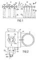
- - la figure 1 représente schématiquement une vue d'ensemble d'un dispositif d'épandage d'engrais liquides: le côté A représentant un dispositif selon l'art antérieur, le côté B représentant un dispositif selon l'invention;
- - la figure 2 représente une coupe selon la ligne II-II de la figure;
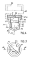
- - la figure 3 représente une vue de dessous de la buse de pulvérisation selon l'invention;
- - la figure 4 représente une coupe selon la ligne III-III de la figure 3;
- - la figure 1 représente schématiquement une vue d'ensemble d'un dispositif d'épandage d'engrais liquides. Ce dispositif comprend une conduite d'arrivée 1 des engrais liquides, relié à un tube de
déviation 3 pouvant être plus ou moins long et muni, par exemple, de plusieurs barillets tels que 5, distribués de façon régulière sur toute la longueur dutube 3 sur lesquels sont fixés plusieurs dispositifs de pulvérisation tels que 7.
- - Figure 1 schematically shows an overview of a liquid fertilizer spreading device: side A representing a device according to the prior art, side B representing a device according to the invention;
- - Figure 2 shows a section along line II-II of the figure;
- - Figure 3 shows a bottom view of the spray nozzle according to the invention;
- - Figure 4 shows a section along line III-III of Figure 3;
- - Figure 1 schematically shows an overview of a liquid fertilizer spreading device. This device comprises an inlet pipe 1 for liquid fertilizers, connected to a
deflection tube 3 which may be more or less long and provided, for example, with several barrels such as 5, distributed regularly over the entire length of thetube 3 to which several spraying devices such as 7 are attached.
Dans l'art antérieur, représente sur le côté A de la figure 1, les dispositifs de pulvérisation 7 sont constitués par des tiges 7a, en général métalliques, percées de plusieurs trous tels que 9a, par exemple, au nombre de trois, dont la dimension varie d'une tige à l'autre, pour des tiges 7a fixées sur un même barillet 5.In the prior art, shown on side A of FIG. 1, the spraying devices 7 consist of rods 7a, generally metallic, pierced with several holes such as 9a, for example, three in number, the dimension varies from one rod to another, for rods 7a fixed on the
Ces tiges 7a peuvent être, par exemple, disposées à 90° l'une de l'autre, pour un même barillet 5. Sur le côté B de la figure 1 représentant le dispositif selon l'invention, les dispositifs de pulvérisation 7 sont constitués par des buses de pulvérisation 7b percées de petits trous 9b.These rods 7a can be, for example, arranged at 90 ° from one another, for the
Dans les deux cas, les barillets 5 sur lesquels sont montés les dispositifs de pulvérisation 7, permettent de sélectionner les dispositifs de pulvérisation désirés, donc la dimension des trous 9 permettant ainsi de définir le débit de pulvérisation des engrais liquides que l'on souhaite. En se référant aux deux parties A et B de la figure, on constate que les dispositifs de pulvérisation selon l'invention, c'est-à-dire les buses 7b, sont nettement moins encombrants que les dispositifs de pulvérisation 7a de l'art antérieur, ce qui permet pour un tube de déviation 3 de longueur donnée de fixer un plus grand nombre de dispositifs de pulvérisation. Cet encombrement plus faible, lié au poids des buses 7b qui sont plus légères que les tiges métalliques 7a, permet de diminuer considérablement l'effet de ballant dû aux tiges 7a, ce qui contribue à la rigidité et à la solidité du dispositif d'épandage, selon l'invention.In both cases, the
De plus, du fait même de la forme des buses de pulverisation 7b qui sera décrite de façon plus détaillée ultérieurement et de la position des trous 9b, les jets de liquide référencés Fb sortent avec un certain axe d'inclinaison par rapport à l'axe de la buse 7b, ce qui permet d'épandre des engrais liquides sur une plus grande surface et ce de façon uniforme, tandis que dans l'art antérieur, les jets de liquide references Fa arrivent, perpendiculairement au sol.
- - la figure 2 représente une coupe selon la ligne II-II de la figure 1. Ce schéma permet de mieux voir la disposition des
buses 7b sur lebarillet 5, relié au tube dedéviation 3 au moyen d'unsupport 11.
- FIG. 2 represents a section along line II-II of FIG. 1. This diagram allows a better view of the arrangement of the
nozzles 7b on thebarrel 5, connected to thedeflection tube 3 by means of asupport 11.
La buse 7b est fixée sur le barillet 5 par example, à l'aide d'un écrou tel que 13 vissé sur une sortie filetée telle que 15 solidaire du barillet 5. Entre la sortie filetée 15 et la buse de pulvérisation 7b, peut être placé un joint d'étanchéité tel que 17. Cette buse 7b comprend de chaque côté un méplat 19 permettant l'orientation des jets d'engrais liquides.The
Cette buse représentée de façon plus détaillée sur les figures 3 et 4, est munie de trous tels que 9b identiques, disposés à égale distance l'un de l'autre et permettant la sortie du liquide. Lorsque ces trous sont au nombre de trois, l'angle entre deux trous voisins 9b est de 120°. Bien entendu, ceci n'est qu'un exemple, car les buses de pulvérisation peuvent comporter 2, 3, 4, 5 trous 9b de sortie, répartis sur une couronne, ce qui assure un écoulement identique pour chacun des trous 9b quelle que soit la pression d'arrivée des engrais liquides.This nozzle shown in more detail in Figures 3 and 4, is provided with holes such as 9b identical, arranged at equal distance from each other and allowing the exit of the liquid. When these holes are three in number, the angle between two neighboring
De plus, les axes de ces trous 9b sont inclinés par rapport à l'axe de la buse 7b d'un angle de préférence égal à 25°.In addition, the axes of these
La buse 7b est constituée d'un corps 21, muni d'une chambre cylindrique 23, de diamètre donné, permettant le passage des engrais liquides dans la buse. Ce corps 21 réalisé de préférence en matière plastique rigide, présente sur sa face 25 de sortie du fluide, une forme conique de sortie que les axes des trous 9b sont perpendiculaires à ladite face 25.The
Cette buse 7b comprend, de plus, une pastille calibrée 27, réalisée de préférence en alumine présentant une pureté de 99,5%, située à l'entrée du liquide dans la buse 7b et définissant un passage 29 pour permettre l'écoulement du liquide dont le diamètre est inférieur au diamètre de la chambre 23. Cette pastille 27 comporte une face concave 31 permettant de limiter le débit du liquide entrant dans la buse 7b et de canaliser celui-ci. En effet, le liquide arrivant sur cette face concave 31, rencontre une restriction 33 du passage 29 créant une perte de charge importante. Ceci permet, ainsi que l'existence d'un passage 29 de diamètre plus petit que le diamètre de la chambre 23, de diminuer le débit de liquide sortant de la buse.This
De plus cette restriction 33 du passage 29 possède un diamètre dont l'ordre de grandeur est situé entre 0,7 mm et 1,8 mm et inférieur au diamètre des trous 9b, dont l'ordre de grandeur est situé entre 1,4 mm et 2,5 mm. Une restriction 33, et des trous 9b plus petits conduiraient à un bouchage de la buse, tandis qu'une restriction 33 et des trous 9b plus grands conduiraient à un débit d'épandage des engrais trop important.In addition, this
Cette pastille 27 peut être placée sur le dessus du corps de la buse 21 et sa section est alors égale à la section de l'extrémité 35 du corps de la buse 21. Dans ces conditions, la pastille 27 est représentée par la référence 27a. Les moyens de fixation de la pastille 27a sont constitués par une bague d'accouplement 37 réalisée de préférence en matière plastique couple, emprisonnant la pastille 27a et venant prendre appui sur l'extrémité 35 du corps de la buse 21, constituant un décrochement.This pad 27 can be placed on top of the body of the
Cette bague d'accouplement est, bien entendu, munie d'une ouverture 39 de façon à permettre l'introduction des engrais liquides dans la buse.This coupling ring is, of course, provided with an
Dans un autre mode de réalisation, la pastille calibrée référence 27b peut être placée dans la chambre 23 du corps de la buse 21. Cette chambre 23 comprenant sur ses parois un décrochement 41 créant une diminution du diamètre de la chambre 23, permet la fixation à force de la pastille 27b dont le diamètre est supérieur au diamètre de la chambre 23 défini après le décrochement 41. De toute façon, quels que soient les moyens de fixation de la pastille 27 sur le corps de la buse 21, ce décrochement 41 existe, ce qui permet à l'agriculteur d'adapter la buse de pulvérisation 7b sur le barillet 5 (figure 2) suivant le diamètre de la sortie filetée 15.In another embodiment, the calibrated
Cette buse suivant la dimension de la restriction 33 du passage 29 et des trous 9b peut délivrer les engrais liquides sous la forme de gouttelettes de 0,5 à 2 mm de diamètre pour une pression d'arrivée des engrais liquides allant de 0,5 à 10 bar, car le débit de pulvérisation des engrais liquides dépend on seulement de la dimension de la restriction 33 et des trous 9b, mais aussi de la pression sous laquelle arrivent les liquides dans la buse.This nozzle, depending on the dimension of the
Le tableau ci-après permet de donner une idée des débits de pulvérisation que l'on peut obtenir suivant la dimension de la restriction et la pression des engrais liquides. Les cas de l'eau de densité 1 et d'un engrais liquide contenant 40% d'azote et de densité 1,28 y sont illustrés. Tableau de debits par buse en litres par minute

Claims (11)
Priority Applications (1)
| Application Number | Priority Date | Filing Date | Title |
|---|---|---|---|
| AT81400264T ATE13390T1 (en) | 1980-02-28 | 1981-02-20 | SPRAY NOZZLE, ESPECIALLY FOR FERTILIZER. |
Applications Claiming Priority (2)
| Application Number | Priority Date | Filing Date | Title |
|---|---|---|---|
| FR8004438A FR2477039A1 (en) | 1980-02-28 | 1980-02-28 | SPRAY NOZZLE, IN PARTICULAR FOR FERTILIZERS |
| FR8004438 | 1980-02-28 |
Publications (2)
| Publication Number | Publication Date |
|---|---|
| EP0037747A1 EP0037747A1 (en) | 1981-10-14 |
| EP0037747B1 true EP0037747B1 (en) | 1985-05-22 |
Family
ID=9239105
Family Applications (1)
| Application Number | Title | Priority Date | Filing Date |
|---|---|---|---|
| EP81400264A Expired EP0037747B1 (en) | 1980-02-28 | 1981-02-20 | Spray nozzle, especially for a fertilizer |
Country Status (13)
| Country | Link |
|---|---|
| US (1) | US4372494A (en) |
| EP (1) | EP0037747B1 (en) |
| AT (1) | ATE13390T1 (en) |
| AU (1) | AU537320B2 (en) |
| BR (1) | BR8101144A (en) |
| CA (1) | CA1167885A (en) |
| DE (1) | DE3170575D1 (en) |
| DK (1) | DK150094C (en) |
| ES (1) | ES264755Y (en) |
| FR (1) | FR2477039A1 (en) |
| IE (1) | IE50818B1 (en) |
| NO (1) | NO156887C (en) |
| ZA (1) | ZA811220B (en) |
Families Citing this family (8)
| Publication number | Priority date | Publication date | Assignee | Title |
|---|---|---|---|---|
| FR2568445B1 (en) * | 1984-08-03 | 1987-07-03 | Desmarquest Ceramiques Tech | SPRAY NOZZLE, ESPECIALLY FOR FERTILIZER. |
| US5003646A (en) * | 1987-04-14 | 1991-04-02 | Hydro Air Industries, Inc. | Hydrotherapy apparatus |
| DE3834670A1 (en) * | 1987-10-14 | 1989-04-27 | Spraying Systems Deutschland G | Nozzle for the discharge of liquid fertiliser |
| DE3914551C1 (en) * | 1989-05-03 | 1990-11-15 | Lechler Gmbh & Co Kg, 7012 Fellbach, De | |
| US4998359A (en) * | 1989-10-02 | 1991-03-12 | The Rhymer Company | Automatic wax lubricator for flatwork ironer |
| DE4230056A1 (en) * | 1992-09-08 | 1994-03-10 | Man Nutzfahrzeuge Ag | Atomizer device |
| ATE298191T1 (en) * | 2001-08-13 | 2005-07-15 | Hardi Int As | JET |
| US11305142B2 (en) * | 2018-01-12 | 2022-04-19 | Carrier Corporation | End cap agent nozzle |
Citations (1)
| Publication number | Priority date | Publication date | Assignee | Title |
|---|---|---|---|---|
| EP0014670A1 (en) * | 1979-02-09 | 1980-08-20 | Berthoud S.A. | Improvements in or relating to sprinkling apparatus |
Family Cites Families (12)
| Publication number | Priority date | Publication date | Assignee | Title |
|---|---|---|---|---|
| US659843A (en) * | 1900-04-26 | 1900-10-16 | George Bray | Construction of gas-burners. |
| US2256729A (en) * | 1937-10-18 | 1941-09-23 | Thompson Mfg Company | Multiple jet sprinkler |
| US2495346A (en) * | 1946-04-06 | 1950-01-24 | Charles H Ramsdell | Sprinkler head |
| US2650132A (en) * | 1950-11-03 | 1953-08-25 | Helen A Reinecke | Sprinkler type irrigating device |
| FR1140623A (en) * | 1956-01-27 | 1957-07-31 | Improvements to sprinklers under water pressure, like sprinklers | |
| US2933259A (en) * | 1958-03-03 | 1960-04-19 | Jean F Raskin | Nozzle head |
| US3191871A (en) * | 1962-05-16 | 1965-06-29 | Golden Arrow Mfg Ltd | Crop sprayers |
| US3130919A (en) * | 1963-02-14 | 1964-04-28 | Baker Res And Dev Corp | Adjustable plastic spray device |
| FR2184247A5 (en) * | 1972-05-08 | 1973-12-21 | Berthoud Sa | |
| GB1376591A (en) * | 1972-06-26 | 1974-12-04 | Franz N C | Nozzle assemblies for use at extremely high fluid pressures |
| DE2437025A1 (en) * | 1974-08-01 | 1976-02-19 | Lechler Apparatebau Kg | DEVICE FOR FASTENING A NOZZLE IN A PIPE |
| US4128206A (en) * | 1977-05-31 | 1978-12-05 | Delavan Corporation | Low drift flat spray nozzle and method |
-
1980
- 1980-02-28 FR FR8004438A patent/FR2477039A1/en active Granted
-
1981
- 1981-02-19 US US06/235,939 patent/US4372494A/en not_active Expired - Fee Related
- 1981-02-20 CA CA000371386A patent/CA1167885A/en not_active Expired
- 1981-02-20 AT AT81400264T patent/ATE13390T1/en active
- 1981-02-20 EP EP81400264A patent/EP0037747B1/en not_active Expired
- 1981-02-20 DE DE8181400264T patent/DE3170575D1/en not_active Expired
- 1981-02-23 NO NO810611A patent/NO156887C/en unknown
- 1981-02-24 ZA ZA00811220A patent/ZA811220B/en unknown
- 1981-02-24 AU AU67573/81A patent/AU537320B2/en not_active Ceased
- 1981-02-25 BR BR8101144A patent/BR8101144A/en not_active IP Right Cessation
- 1981-02-25 IE IE383/81A patent/IE50818B1/en not_active IP Right Cessation
- 1981-02-26 DK DK086281A patent/DK150094C/en not_active IP Right Cessation
- 1981-02-27 ES ES1981264755U patent/ES264755Y/en not_active Expired
Patent Citations (1)
| Publication number | Priority date | Publication date | Assignee | Title |
|---|---|---|---|---|
| EP0014670A1 (en) * | 1979-02-09 | 1980-08-20 | Berthoud S.A. | Improvements in or relating to sprinkling apparatus |
Also Published As
| Publication number | Publication date |
|---|---|
| DE3170575D1 (en) | 1985-06-27 |
| DK86281A (en) | 1981-08-29 |
| IE810383L (en) | 1981-08-28 |
| AU537320B2 (en) | 1984-06-14 |
| BR8101144A (en) | 1981-09-01 |
| NO156887C (en) | 1987-12-16 |
| ES264755Y (en) | 1983-06-01 |
| DK150094B (en) | 1986-12-08 |
| ZA811220B (en) | 1982-03-31 |
| ATE13390T1 (en) | 1985-06-15 |
| IE50818B1 (en) | 1986-07-23 |
| EP0037747A1 (en) | 1981-10-14 |
| NO810611L (en) | 1981-08-31 |
| CA1167885A (en) | 1984-05-22 |
| FR2477039A1 (en) | 1981-09-04 |
| DK150094C (en) | 1987-06-15 |
| US4372494A (en) | 1983-02-08 |
| FR2477039B1 (en) | 1984-12-07 |
| ES264755U (en) | 1982-12-01 |
| NO156887B (en) | 1987-09-07 |
| AU6757381A (en) | 1981-09-03 |
Similar Documents
| Publication | Publication Date | Title |
|---|---|---|
| BE1006591A6 (en) | Distribution system fluid spray jets. | |
| EP0037747B1 (en) | Spray nozzle, especially for a fertilizer | |
| FR2516892A1 (en) | FUEL TANK | |
| FR2511971A1 (en) | OUTPUT TUBING FOR LIQUID FILLING DEVICES | |
| CH615606A5 (en) | ||
| FR2928567A1 (en) | LIQUID SPRAY NOZZLE AND LIQUID SPRAYER COMPRISING SUCH A NOZZLE | |
| FR2486499A1 (en) | DOSING DEVICE WITH BALL VALVE AND METHOD FOR OPERATING THE SAME | |
| EP1032464B1 (en) | Liquid dispenser for non-vertical distilling column, and distilling column equipped therewith | |
| EP1804926A1 (en) | Low-pressure flow-controlled powder spreader | |
| FR3016302A1 (en) | STATIC MIXER FOR HOMOGENIZING A MIXTURE OF AT LEAST TWO LIQUIDS AND DOSING DEVICE EQUIPPED WITH SUCH A MIXER | |
| FR2477038A1 (en) | Fungicide liquid spray nozzle - has throttle disc with concave inlet face fixed to two-part nozzle | |
| FR2540405A3 (en) | Spray boom for agriculture | |
| FR2785770A1 (en) | Suspended nozzle column for spraying fence-trained crops, e.g. vines, comprises hollow vertical casing, supporting nozzles at variable heights, hanging from vehicle-borne rack | |
| BE1000264A6 (en) | Machine for producing atomised jet of liquid - has row of nozzles with each nozzle inlet fitted with grid | |
| EP0284512B1 (en) | Feeding device by gravity for a paint spray gun | |
| FR2892893A1 (en) | Treatment product spray gun for e.g. vineyard, has hollow tubular shaped arm with insert having housing in which spreading nozzles are fixed in order to withdraw nozzles with respect to external surface of arm | |
| FR2551318A1 (en) | IMPACT DRIVING WATERING APPARATUS | |
| EP0014670A1 (en) | Improvements in or relating to sprinkling apparatus | |
| FR2789852A1 (en) | Bait device has container with inlet for water, second inlet for bait and outlet for mixture of bait and water, taps connected to water inlet and outlet, and hose attached to outlet tap with clip | |
| EP0124672A1 (en) | Device for treating cultures by moistening | |
| FR2568445A1 (en) | Spray nozzle especially for fertilizers | |
| EP0117863B1 (en) | Method and apparatus for spraying a liquid | |
| FR2552462A1 (en) | Injection tube for soil strengthening products | |
| FR2737232A1 (en) | APPARATUS FOR TRACING LINES ON THE GROUND | |
| FR2641201A1 (en) | Device for creating a water curtain |
Legal Events
| Date | Code | Title | Description |
|---|---|---|---|
| PUAI | Public reference made under article 153(3) epc to a published international application that has entered the european phase |
Free format text: ORIGINAL CODE: 0009012 |
|
| AK | Designated contracting states |
Designated state(s): AT BE CH DE GB IT LU NL SE |
|
| ITCL | It: translation for ep claims filed |
Representative=s name: JACOBACCI CASETTA & PERANI S.P.A. |
|
| TCNL | Nl: translation of patent claims filed | ||
| 17P | Request for examination filed |
Effective date: 19820322 |
|
| TCAT | At: translation of patent claims filed | ||
| RAP1 | Party data changed (applicant data changed or rights of an application transferred) |
Owner name: LAFARGE REFRACTAIRES SOCIETE ANONYME |
|
| DET | De: translation of patent claims | ||
| RAP1 | Party data changed (applicant data changed or rights of an application transferred) |
Owner name: LAFARGE REFRACTAIRES SOCIETE ANONYME |
|
| DET | De: translation of patent claims | ||
| REG | Reference to a national code |
Ref country code: DE Ref legal event code: 8580 Free format text: DER HINWEIS IST ZU STREICHEN. DER DEUTSCHE VEROEFFENTLICHUNGSTAG LAUTET RICHTIG: 02.09.82 |
|
| ITF | It: translation for a ep patent filed |
Owner name: JACOBACCI & PERANI S.P.A. |
|
| GRAA | (expected) grant |
Free format text: ORIGINAL CODE: 0009210 |
|
| AK | Designated contracting states |
Designated state(s): AT BE CH DE GB IT LI LU NL SE |
|
| REF | Corresponds to: |
Ref document number: 13390 Country of ref document: AT Date of ref document: 19850615 Kind code of ref document: T |
|
| REF | Corresponds to: |
Ref document number: 3170575 Country of ref document: DE Date of ref document: 19850627 |
|
| BECA | Be: change of holder's address |
Free format text: 850522 *CERAMIQUES TECHNIQUES DESMARQUEST23 RUE BALZAC, F-75008 PARIS |
|
| BECH | Be: change of holder |
Free format text: 850522 *CERAMIQUES TECHNIQUES DESMARQUEST |
|
| PLBE | No opposition filed within time limit |
Free format text: ORIGINAL CODE: 0009261 |
|
| STAA | Information on the status of an ep patent application or granted ep patent |
Free format text: STATUS: NO OPPOSITION FILED WITHIN TIME LIMIT |
|
| 26N | No opposition filed | ||
| REG | Reference to a national code |
Ref country code: CH Ref legal event code: PUE Owner name: CERAMIQUES TECHNIQUES DESMARQUEST |
|
| REG | Reference to a national code |
Ref country code: GB Ref legal event code: 732 |
|
| NLS | Nl: assignments of ep-patents |
Owner name: CERAMIQUES TECHNIQUES DESMARQUEST TE PARIJS, FRANK |
|
| ITPR | It: changes in ownership of a european patent |
Owner name: CESSIONE;CERAMIQUES TECHNIQUES DESMARQUEST |
|
| PGFP | Annual fee paid to national office [announced via postgrant information from national office to epo] |
Ref country code: LU Payment date: 19930127 Year of fee payment: 13 |
|
| PGFP | Annual fee paid to national office [announced via postgrant information from national office to epo] |
Ref country code: SE Payment date: 19930129 Year of fee payment: 13 |
|
| PGFP | Annual fee paid to national office [announced via postgrant information from national office to epo] |
Ref country code: AT Payment date: 19930212 Year of fee payment: 13 |
|
| ITTA | It: last paid annual fee | ||
| EPTA | Lu: last paid annual fee | ||
| PG25 | Lapsed in a contracting state [announced via postgrant information from national office to epo] |
Ref country code: LU Free format text: LAPSE BECAUSE OF NON-PAYMENT OF DUE FEES Effective date: 19940220 Ref country code: AT Effective date: 19940220 |
|
| PG25 | Lapsed in a contracting state [announced via postgrant information from national office to epo] |
Ref country code: SE Effective date: 19940221 |
|
| EUG | Se: european patent has lapsed |
Ref document number: 81400264.8 Effective date: 19940910 |
|
| PGFP | Annual fee paid to national office [announced via postgrant information from national office to epo] |
Ref country code: NL Payment date: 19980228 Year of fee payment: 18 |
|
| PGFP | Annual fee paid to national office [announced via postgrant information from national office to epo] |
Ref country code: GB Payment date: 19980303 Year of fee payment: 18 |
|
| PGFP | Annual fee paid to national office [announced via postgrant information from national office to epo] |
Ref country code: CH Payment date: 19980324 Year of fee payment: 18 |
|
| PGFP | Annual fee paid to national office [announced via postgrant information from national office to epo] |
Ref country code: BE Payment date: 19980416 Year of fee payment: 18 |
|
| PGFP | Annual fee paid to national office [announced via postgrant information from national office to epo] |
Ref country code: DE Payment date: 19980425 Year of fee payment: 18 |
|
| PG25 | Lapsed in a contracting state [announced via postgrant information from national office to epo] |
Ref country code: GB Free format text: LAPSE BECAUSE OF NON-PAYMENT OF DUE FEES Effective date: 19990220 |
|
| PG25 | Lapsed in a contracting state [announced via postgrant information from national office to epo] |
Ref country code: LI Free format text: LAPSE BECAUSE OF NON-PAYMENT OF DUE FEES Effective date: 19990228 Ref country code: CH Free format text: LAPSE BECAUSE OF NON-PAYMENT OF DUE FEES Effective date: 19990228 Ref country code: BE Free format text: LAPSE BECAUSE OF NON-PAYMENT OF DUE FEES Effective date: 19990228 |
|
| BERE | Be: lapsed |
Owner name: CERAMIQUES TECHNIQUES DESMARQUEST Effective date: 19990228 |
|
| PG25 | Lapsed in a contracting state [announced via postgrant information from national office to epo] |
Ref country code: NL Free format text: LAPSE BECAUSE OF NON-PAYMENT OF DUE FEES Effective date: 19990901 |
|
| GBPC | Gb: european patent ceased through non-payment of renewal fee |
Effective date: 19990220 |
|
| REG | Reference to a national code |
Ref country code: CH Ref legal event code: PL |
|
| PG25 | Lapsed in a contracting state [announced via postgrant information from national office to epo] |
Ref country code: DE Free format text: LAPSE BECAUSE OF NON-PAYMENT OF DUE FEES Effective date: 19991201 |