EP0284512B1 - Feeding device by gravity for a paint spray gun - Google Patents
Feeding device by gravity for a paint spray gun Download PDFInfo
- Publication number
- EP0284512B1 EP0284512B1 EP19880400714 EP88400714A EP0284512B1 EP 0284512 B1 EP0284512 B1 EP 0284512B1 EP 19880400714 EP19880400714 EP 19880400714 EP 88400714 A EP88400714 A EP 88400714A EP 0284512 B1 EP0284512 B1 EP 0284512B1
- Authority
- EP
- European Patent Office
- Prior art keywords
- gun
- connector
- paint
- coupling element
- reservoir
- Prior art date
- Legal status (The legal status is an assumption and is not a legal conclusion. Google has not performed a legal analysis and makes no representation as to the accuracy of the status listed.)
- Expired - Lifetime
Links
Images

Classifications
-
- B—PERFORMING OPERATIONS; TRANSPORTING
- B05—SPRAYING OR ATOMISING IN GENERAL; APPLYING FLUENT MATERIALS TO SURFACES, IN GENERAL
- B05B—SPRAYING APPARATUS; ATOMISING APPARATUS; NOZZLES
- B05B7/00—Spraying apparatus for discharge of liquids or other fluent materials from two or more sources, e.g. of liquid and air, of powder and gas
- B05B7/24—Spraying apparatus for discharge of liquids or other fluent materials from two or more sources, e.g. of liquid and air, of powder and gas with means, e.g. a container, for supplying liquid or other fluent material to a discharge device
- B05B7/2402—Apparatus to be carried on or by a person, e.g. by hand; Apparatus comprising containers fixed to the discharge device
- B05B7/2405—Apparatus to be carried on or by a person, e.g. by hand; Apparatus comprising containers fixed to the discharge device using an atomising fluid as carrying fluid for feeding, e.g. by suction or pressure, a carried liquid from the container to the nozzle
- B05B7/2408—Apparatus to be carried on or by a person, e.g. by hand; Apparatus comprising containers fixed to the discharge device using an atomising fluid as carrying fluid for feeding, e.g. by suction or pressure, a carried liquid from the container to the nozzle characterised by the container or its attachment means to the spray apparatus
- B05B7/2413—Apparatus to be carried on or by a person, e.g. by hand; Apparatus comprising containers fixed to the discharge device using an atomising fluid as carrying fluid for feeding, e.g. by suction or pressure, a carried liquid from the container to the nozzle characterised by the container or its attachment means to the spray apparatus with means for changing the position or the orientation of the container relative to the spray apparatus
-
- B—PERFORMING OPERATIONS; TRANSPORTING
- B05—SPRAYING OR ATOMISING IN GENERAL; APPLYING FLUENT MATERIALS TO SURFACES, IN GENERAL
- B05B—SPRAYING APPARATUS; ATOMISING APPARATUS; NOZZLES
- B05B7/00—Spraying apparatus for discharge of liquids or other fluent materials from two or more sources, e.g. of liquid and air, of powder and gas
- B05B7/24—Spraying apparatus for discharge of liquids or other fluent materials from two or more sources, e.g. of liquid and air, of powder and gas with means, e.g. a container, for supplying liquid or other fluent material to a discharge device
- B05B7/2402—Apparatus to be carried on or by a person, e.g. by hand; Apparatus comprising containers fixed to the discharge device
- B05B7/2478—Gun with a container which, in normal use, is located above the gun
Definitions
- the invention relates to paint or similar material spray guns and, more particularly, it relates to the system for supplying such guns with paint or other material to be sprayed.
- Spray guns of this type currently known are generally supplied with paint from a reservoir cup which is disposed under the spray gun while being connected to the spray orifice thereof by a duct oriented perpendicular to the axis of the spray gun. .
- This arrangement of the paint reservoir cup sometimes proves to be impractical when the configuration of the parts to be painted requires orienting the spray gun in certain positions.
- Document FR-A-2363375 discloses a compressed air gun for spraying fluid substances such as paint, which in its embodiment of FIGS. 2 and 3, is equipped with a gravity feed device .
- the paint container is connected laterally by means of a sleeve which is mounted for free rotation on a hollow shaft opening into the gun.
- An annular chamber is formed between the sleeve and the hollow shaft, and communicates with an internal channel of the latter.
- the object of the present invention is to remedy the drawbacks presented by known supply devices for spray guns for painting or the like, and for this purpose it proposes a gravity supply device which, while being of a great simplicity and low cost, ensures a perfect supply of paint to the gun regardless of the inclination given to it, with an excellent seal without the use of seals and which allows the gun to be perfectly balanced in the hand regardless of its position of use.
- the gun is supplied from a connector which projects laterally with respect to the body of the gun, being oriented in a direction practically perpendicular to the plane of the latter.
- This hollow connection engages the hollow interior part of a connecting piece into which opens, via a rigid conduit, the open lower end of the bucket forming a paint reservoir.
- the body of the fitting On its intermediate part, has a groove profile with radial openings allowing the paint to flow. inside the fitting.
- Conical surfaces on the opposite faces of the connecting piece are designed which, in the device's position of use, are clamped against parts of conjugated conical shape presented on the one hand by one end of the body of the fitting and, on the other hand, by a blind clamping nut screwing onto the threaded free end of the fitting.
- the device thus achieves, by tightening the nut, an excellent seal that does not require the use of seals and that it allows, depending on the position of use of the gun, to adjust the inclination of the bucket by pivot around the fitting, and fix the bucket in the position thus chosen, so as to always allow a good flow by gravity of the paint out of the bucket and a good balancing of the device in the hand of the user.
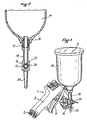
- a spray gun for spraying paint with at 2 a compressed air inlet pipe extending the butt 3, at 4 the spray nozzle and at 5 the control trigger.
- a tubular connector 6 projects from the front part of the gun 1, the inner end 7 of this connector opening into a supply chamber (not shown in the drawing) located upstream of the spray nozzle 4.
- the body of the connector 6 has, from its inner end 7, a portion 8 of larger diameter continuing with a conical portion 9 itself extended by a cylindrical portion 10.
- the cylindrical portion 10 has a groove peripheral 11 radially pierced with four openings 12 communicating with the interior of the fitting. The body of the latter ends outwards by a threaded part 13.
- the bucket 14, forming a paint reservoir is made of a rigid plastic material and has a cylindrical body continuing at its base by a conical part in the form of a funnel.
- the bucket 14 is closed at its upper part by a screwable cover 15 and it has at its lower end an outlet orifice 16 which is screwed into the upper part 17 of a rigid conduit 18 having at its intermediate part a connecting piece 19.
- the part 19 has, oriented perpendicular to the axis of the rod 18, a bore 20 of circular section at the upper part of which opens, through an opening 21, the end of the hollow rod 18.
- the part 19 has a conical bearing surface respectively 22, 23 and it continues, at its lower part, with a support leg 24.
- the part 19 is designed to receive, in its bore 20, the body of the connector 6, the conical surface 22 of the part 19 coming to apply in sealed manner against the conjugate conical part 9 of the connector 6.
- a cap nut 25, having at its open end a conical part 26 is screwed onto the threaded end 13 of the body of the connector 6 so that this conical part 26 comes engage the conjugate conical bearing surface 23 of the connecting piece 19.
- the lengths of the connector 6 and of the conduit 18 are provided such that the cup 14 projects laterally above the gun 1 while being disposed in a vertical plane very close to it so as not to unbalance the gun in use .
- the mounting of the cup 14 on the connector 6 allows, before tightening the nut 25, to orient the inclination of the cup at will in a plane parallel to that of the gun, so, according to the position of use gun, on the one hand to permanently ensure a good supply of paint and, on the other hand, good balancing of the gun in the hand of the user.
- the bucket 14 is then immobilized in this position by tightening the nut 25.
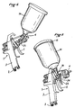
- the gun has been shown in a position suitable for painting a horizontal surface, the bucket 14 then being inclined widely backwards allowing good flow of the paint by gravity out of the bucket and good balancing. of the spray gun whereas, in this position, a traditional gravity feed spray gun would be unbalanced forwards by the weight of the paint contained in the bucket.
- the spray gun is shown in a position suitable for painting a vertical surface, the cup 14 then being in an intermediate position slightly inclined towards the rear, and in FIG. 6, the spray gun 1 is shown in a suitable position. to paint from below a surface inside, the bucket 14 then being in a very forward tilted position.
- the position shown in FIG. 1 also corresponds to a position for laying the gun when it is not in use and it can then be seen that the cup 14 can advantageously be oriented so that the end of the leg d 'support 24 engages the support surface by constituting a stand which ensures stable positioning of the gun.
Description
L'invention concerne les pistolets de pulvérisation de peinture ou de matière analogue et, plus particulièrement, elle est relative au système d'alimentation de tels pistolets en peinture ou autre matière à pulvériser.The invention relates to paint or similar material spray guns and, more particularly, it relates to the system for supplying such guns with paint or other material to be sprayed.
Les pistolets de ce type actuellement connus sont généralement alimentés en peinture à partir d'un godet formant réservoir qui est disposé sous le pistolet en étant relié à l'orifice de pulvérisation de celui-ci par un conduit orienté perpendiculairement à l'axe du pistolet. Cette disposition du godet formant réservoir de peinture se révèle parfois peu pratique lorsque la configuration des pièces à peindre oblige à orienter le pistolet dans certaines positions. De plus, il est nécessaire de prévoir un système d'aspiration pour assurer la montée de la peinture contenue dans le godet jusqu'à l'orifice de pulvérisation, ce qui complique la structure de l'appareil.Spray guns of this type currently known are generally supplied with paint from a reservoir cup which is disposed under the spray gun while being connected to the spray orifice thereof by a duct oriented perpendicular to the axis of the spray gun. . This arrangement of the paint reservoir cup sometimes proves to be impractical when the configuration of the parts to be painted requires orienting the spray gun in certain positions. In addition, it is necessary to provide a suction system to ensure the rise of the paint contained in the bucket to the spray orifice, which complicates the structure of the device.
On a aussi proposé d'alimenter le pistolet par gravité en plaçant le godet formant réservoir de peinture au-dessus du pistolet, selon une orientation pratiquement perpendiculaire à l'axe de celui-ci, l'orifice inférieur de sortie du godet venant se fixer rigidement sur un raccord disposé dans le plan vertical médian du pistolet, au voisinage de l'orifice de pulvérisation de celui-ci. Ces pistolets connus à alimentation par gravité ont l'avantage de dispenser l'appareil d'un système d'alimentation par aspiration mais ils présentent l'inconvénient que, lorsque l'utilisateur doit incliner le pistolet dans certaines positions nécessaires par exemple pour peindre des surfaces horizontales ou la face intérieure de certaines pièces, d'une part l'alimentation du pistolet peut être perturbée et, d'autre part, le pistolet se trouve déséquilibré par le poids de la peinture contenue dans le godet ce qui est un obstacle à une bonne utilisation de l'appareil.It has also been proposed to feed the gun by gravity by placing the bucket forming a paint tank. above the gun, in an orientation practically perpendicular to the axis of the latter, the lower outlet opening of the cup rigidly fixing itself on a fitting arranged in the vertical vertical plane of the gun, in the vicinity of the orifice spraying it. These known spray guns with gravity feed have the advantage of dispensing the device from a suction feed system but they have the disadvantage that when the user has to tilt the gun in certain positions necessary for example for painting horizontal surfaces or the inside of certain parts, on the one hand the gun supply can be disturbed and, on the other hand, the gun is unbalanced by the weight of the paint contained in the bucket which is an obstacle to proper use of the device.
Par le document FR-A-2363375 est connu un pistolet à air comprimé pour la projection de substances fluides telles que de la peinture, qui dans sa forme de réalisation des figures 2 et 3, est équipé d'un dispositif d'alimentation par gravité. A cet effet le récipient à peinture est branché latéralement au moyen d'un manchon qui est monté à rotation libre sur un arbre creux débouchant dans le pistolet. Une chambre annulaire est ménagée entre le manchon et l'arbre creux, et communique avec un canal interne de ce dernier. Par son montage à rotation libre le récipient peut osciller pour rester constamment vertical quelle que soit l'inclinaison du canon de pistolet par rapport à l'horizontale. Pour un fonctionnement par gravité il est prévu de fixer sous le manchon un contrepoids plus lourd que le récipient chargé.Document FR-A-2363375 discloses a compressed air gun for spraying fluid substances such as paint, which in its embodiment of FIGS. 2 and 3, is equipped with a gravity feed device . For this purpose the paint container is connected laterally by means of a sleeve which is mounted for free rotation on a hollow shaft opening into the gun. An annular chamber is formed between the sleeve and the hollow shaft, and communicates with an internal channel of the latter. By its assembly with free rotation the container can oscillate to remain constantly vertical whatever the inclination of the pistol barrel with respect to the horizontal. For gravity operation it is planned to fix a heavier counterweight under the sleeve than the loaded container.
La présente invention a pour objet de remédier aux inconvénients présentés par les dispositifs d'alimentation connus pour pistolets de pulvérisation de peinture ou de matière analogue, et elle propose à cet effet un dispositif d'alimentation par gravité qui, tout en étant d'une grande simplicité et d'un faible coût, assure une parfaite alimentation en peinture du pistolet quelle que soit l'inclinaison donnée à celui-ci, avec une excellente étanchéité sans utilisation de joints et qui permet au pistolet d'être parfaitement équilibré dans la main de l'utilisateur, quelle que soit sa position d'utilisation.The object of the present invention is to remedy the drawbacks presented by known supply devices for spray guns for painting or the like, and for this purpose it proposes a gravity supply device which, while being of a great simplicity and low cost, ensures a perfect supply of paint to the gun regardless of the inclination given to it, with an excellent seal without the use of seals and which allows the gun to be perfectly balanced in the hand regardless of its position of use.
Selon l'invention, l'alimentation du pistolet s'effectue à partir d'un raccord qui fait saillie latéralement par rapport au corps du pistolet en étant orienté dans une direction pratiquement perpendiculaire au plan de celui-ci. Sur ce raccord vient s'engager la partie intérieure creuse d'une pièce de liaison dans laquelle débouche, par l'intermédiaire d'un conduit rigide, l'extrémité inférieure ouverte du godet formant réservoir de peinture. Sur sa partie intermédiaire, le corps du raccord présente un profil de gorge avec des ouvertures radiales permettant l'écoulement de la peinture à l'intérieur du raccord. Sur les faces opposées de la pièce de liaison sont pratiquées des portées coniques qui sont destinées, en position d'utilisation du dispositif, à être serrées contre des parties de forme conique conjuguées présentées d'une part par une extrémité du corps du raccord et, d'autre part, par un écrou de serrage borgne se vissant sur l'extrémité libre filetée du raccord.According to the invention, the gun is supplied from a connector which projects laterally with respect to the body of the gun, being oriented in a direction practically perpendicular to the plane of the latter. This hollow connection engages the hollow interior part of a connecting piece into which opens, via a rigid conduit, the open lower end of the bucket forming a paint reservoir. On its intermediate part, the body of the fitting has a groove profile with radial openings allowing the paint to flow. inside the fitting. Conical surfaces on the opposite faces of the connecting piece are designed which, in the device's position of use, are clamped against parts of conjugated conical shape presented on the one hand by one end of the body of the fitting and, on the other hand, by a blind clamping nut screwing onto the threaded free end of the fitting.
On comprend que le dispositif réalise ainsi, par serrage de l'écrou, une excellente étanchéité ne nécessitant pas l'utilisation de joints et qu'il permet, suivant la position d'utilisation du pistolet, d'adapter l'inclinaison du godet par pivotement autour du raccord, et de fixer le godet dans la position ainsi choisie, de façon à toujours permettre un bon écoulement par gravité de la peinture hors du godet et un bon équilibrage de l'appareil dans la main de l'utilisateur.It is understood that the device thus achieves, by tightening the nut, an excellent seal that does not require the use of seals and that it allows, depending on the position of use of the gun, to adjust the inclination of the bucket by pivot around the fitting, and fix the bucket in the position thus chosen, so as to always allow a good flow by gravity of the paint out of the bucket and a good balancing of the device in the hand of the user.
Pour bien faire comprendre le dispositif selon la présente invention, on en décrira ci-après, à titre d'exemple sans caractère limitatif, une forme d'exécution préférée en référence au dessin schématique annexé dans lequel:
- la figure 1 est une vue de côté d'un pistolet pulvérisateur équipé d'un système d'alimentation par gravité selon l'invention, le pistolet étant représenté dans une position adaptée pour peindre une surface horizontale;
- la figure 2 est une vue en coupe verticale longitudinale du conduit d'alimentation fixé à la sortie du godet formant réservoir et du raccord avec lequel il coopère;
- la figure 3 est une coupe verticale transversale montrant la fixation du conduit d'alimentation en peinture sur le raccord;
- la figure 4 est une vue éclatée montrant le dispositif d'alimentation selon l'invention; et
- les figures 5 et 6 montrent le pistolet de la figure 1 dans deux autres positions de travail correspondant respectivement au traitement d'une surface verticale et d'une surface intérieure.
- Figure 1 is a side view of a spray gun equipped with a gravity feed system according to the invention, the gun being shown in a position suitable for painting a horizontal surface;
- Figure 2 is a longitudinal vertical sectional view of the supply duct fixed at the outlet of the reservoir cup and the connector with which it cooperates;
- Figure 3 is a vertical cross section showing the attachment of the paint supply conduit on the connector;
- Figure 4 is an exploded view showing the feed device according to the invention; and
- Figures 5 and 6 show the gun of Figure 1 in two other working positions corresponding respectively to the treatment of a vertical surface and an interior surface.
Au dessin on a représenté en 1 un pistolet pour la pulvérisation de peinture, avec en 2 une tubulure d'arrivée d'air comprimé prolongeant la crosse 3, en 4 la buse de pulvérisation et en 5 la gâchette de commande.In the drawing, there is shown at 1 a spray gun for spraying paint, with at 2 a compressed air inlet pipe extending the
Un raccord tubulaire 6 fait saillie à partir de la partie avant du pistolet 1, l'extrémité intérieure 7 de ce raccord débouchant dans une chambre d'alimentation (non représentée au dessin) située en amont de la buse de pulvérisation 4. Extérieurement, le corps du raccord 6 présente, à partir de son extrémité intérieure 7, une partie 8 de plus grand diamètre se poursuivant par une partie conique 9 prolongée elle-même par une portion cylindrique 10. A sa partie centrale, la portion cylindrique 10 comporte une gorge périphérique 11 percée radialement de quatre ouvertures 12 communiquant avec l'intérieur du raccord. Le corps de ce dernier se termine vers l'extérieur par une partie filetée 13.A
Le godet 14, formant réservoir de peinture, est réalisé en une matière plastique rigide et présente un corps cylindrique se poursuivant à sa base par une partie conique en forme d'entonnoir. Le godet 14 est fermé à sa partie supérieure par un couvercle vissable 15 et il présente à son extrémité inférieure un orifice de sortie 16 qui vient se visser dans la partie supérieure 17 d'un conduit rigide 18 présentant à sa partie intermédiaire une pièce de liaison 19. La pièce 19 présente, orientée perpendiculairement à l'axe de la tige 18, un perçage 20 à section circulaire à la partie supérieure duquel débouche, par une ouverture 21, l'extrémité de la tige creuse 18. A chacune de ses extrémités, la pièce 19 comporte une portée conique respectivement 22, 23 et elle se poursuit, à sa partie inférieure, par une jambe d'appui 24.The
La pièce 19 est conçue pour recevoir, dans son perçage 20, le corps du raccord 6, la portée conique 22 de la pièce 19 venant s'appliquer de façon étanche contre la partie conique conjuguée 9 du raccord 6. Un écrou borgne 25, présentant à son extrémité ouverte une partie conique 26, se visse sur l'extrémité filetée 13 du corps du raccord 6 de façon que cette partie conique 26 vienne engager la portée conique conjuguée 23 de la pièce de liaison 19. Par serrage de l'écrou 25, on obtient ainsi, sans utilisation de joints susceptibles d'être détériorés par la peinture, une fixation parfaitement étanche du godet 14 sur le raccord 6 du pistolet 1.The
En position de fixation du godet 14 l'ouverture 21, par laquelle s'écoule par gravité la peinture contenue dans le godet 14, vient en regard de la gorge 11 du raccord 6, en permettant le passage de la peinture par les ouvertures 12 vers l'intérieur du pistolet 1.In the
Les longueurs du raccord 6 et du conduit 18 sont prévues telles que le godet 14 déborde latéralement au-dessus du pistolet 1 en étant disposé dans un plan vertical très proche de celui-ci de façon à ne pas déséquilibrer le pistolet en cours d'utilisation.The lengths of the
On comprend que le montage du godet 14 sur le raccord 6 permet, avant serrage de l'écrou 25, d'orienter à volonté l'inclinaison du godet dans un plan parallèle à celui du pistolet, de façon, selon la position d'utilisation du pistolet, d'une part à assurer en permanence une bonne alimentation en peinture et, d'autre part, un bon équilibrage du pistolet dans la main de l'utilisateur. Lorsque l'orientation désirée est atteinte, on immobilise alors le godet 14 dans cette position par serrage de l'écrou 25.It is understood that the mounting of the
A la figure 1 on a représenté le pistolet dans une position adaptée à la peinture d'une surface horizontale, le godet 14 étant alors largement incliné vers l'arrière en permettant un bon écoulement par gravité de la peinture hors du godet et un bon équilibrage du pistolet alors que, dans cette position, un pistolet traditionnel à alimentation par gravité serait déséquilibré vers l'avant par le poids de la peinture contenue dans le godet. A la figure 5, le pistolet est représenté dans une position appropriée pour peindre une surface verticale, le godet 14 étant alors dans une position intermédiaire légèrement inclinée vers l'arrière, et à la figure 6 on a représenté le pistolet 1 dans une position adaptée pour peindre par en dessous une surface intérieure, le godet 14 se trouvant alors dans une position très inclinée vers l'avant.In FIG. 1, the gun has been shown in a position suitable for painting a horizontal surface, the
La position représentée à la figure 1 correspond également à une position de pose du pistolet lorsque celui-ci n'est pas utilisé et l'on voit alors qu'on peut avantageusement orienter le godet 14 de façon que l'extrémité de la jambe d'appui 24 engage la surface de support en constituant une béquille qui assure un positionnement stable du pistolet.The position shown in FIG. 1 also corresponds to a position for laying the gun when it is not in use and it can then be seen that the
On comprendra que la description ci-dessus a été donnée à simple titre d'exemple, sans caractère limitatif, et que des adjonctions ou des modifications constructives pourraient y être apportées sans sortir du cadre de l'invention définie par les revendications qui suivent.It will be understood that the above description has been given by way of example, without limitation, and that additions or constructive modifications could be made without departing from the scope of the invention defined by the claims which follow.
Claims (3)
Applications Claiming Priority (2)
| Application Number | Priority Date | Filing Date | Title |
|---|---|---|---|
| FR8704048 | 1987-03-24 | ||
| FR8704048A FR2612810B1 (en) | 1987-03-24 | 1987-03-24 | GRAVITY FEEDING DEVICE FOR A SPRAY GUN FOR PAINT OR THE LIKE |
Publications (2)
| Publication Number | Publication Date |
|---|---|
| EP0284512A1 EP0284512A1 (en) | 1988-09-28 |
| EP0284512B1 true EP0284512B1 (en) | 1991-08-07 |
Family
ID=9349349
Family Applications (1)
| Application Number | Title | Priority Date | Filing Date |
|---|---|---|---|
| EP19880400714 Expired - Lifetime EP0284512B1 (en) | 1987-03-24 | 1988-03-24 | Feeding device by gravity for a paint spray gun |
Country Status (3)
| Country | Link |
|---|---|
| EP (1) | EP0284512B1 (en) |
| DE (1) | DE3864047D1 (en) |
| FR (1) | FR2612810B1 (en) |
Families Citing this family (2)
| Publication number | Priority date | Publication date | Assignee | Title |
|---|---|---|---|---|
| DE4416939A1 (en) * | 1994-05-13 | 1995-11-16 | Bruno Jesswein Kunststofftechn | Spray gun |
| FR2784314B1 (en) * | 1998-10-09 | 2001-09-21 | Patrick Martinez | DEVICE FOR THE GRAVITY FEEDING OF A SPRAYER, PARTICULARLY PAINT |
Family Cites Families (4)
| Publication number | Priority date | Publication date | Assignee | Title |
|---|---|---|---|---|
| DE325593C (en) * | 1918-11-17 | 1920-09-15 | Karl Schwarz | Pipe joint |
| US3219366A (en) * | 1962-02-20 | 1965-11-23 | Imp Eastman Corp | Reinforced fluid control fitting |
| FR1337432A (en) * | 1962-08-01 | 1963-09-13 | Universal spray gun | |
| FR2363375A1 (en) * | 1976-09-01 | 1978-03-31 | Boulot Annic | Spray pistol for fluids or powders - has adjustable spray width with feed by gravity, suction or through pressure pot |
-
1987
- 1987-03-24 FR FR8704048A patent/FR2612810B1/en not_active Expired
-
1988
- 1988-03-24 EP EP19880400714 patent/EP0284512B1/en not_active Expired - Lifetime
- 1988-03-24 DE DE8888400714T patent/DE3864047D1/en not_active Expired - Fee Related
Also Published As
| Publication number | Publication date |
|---|---|
| FR2612810B1 (en) | 1989-06-16 |
| DE3864047D1 (en) | 1991-09-12 |
| FR2612810A1 (en) | 1988-09-30 |
| EP0284512A1 (en) | 1988-09-28 |
Similar Documents
| Publication | Publication Date | Title |
|---|---|---|
| CA2332472C (en) | Adjustable gripping device for the transportation or the machining of parts of different shapes | |
| FR2900583A1 (en) | TEXTURE SPRAYER | |
| FR2576225A1 (en) | MANUALLY OPERATED SPRAYER WITH ADJUSTMENT OF THE CONFIGURATION OF THE SPRAYED LIQUID | |
| FR2565130A1 (en) | MANUAL SPRAYER AND DIAPHRAGM PUMP FOR SPRAYER | |
| FR2481955A1 (en) | ATOMIZING DISC LIQUID SPRAY APPARATUS | |
| EP3827902B1 (en) | Kit for a spray gun, method of use and associated gun | |
| FR2669560A1 (en) | HAND SPRAYER MOUNTED ON A CONTAINER WITH INCLINED NECK. | |
| FR2526681A1 (en) | ROTARY WATER IRRIGATION APPARATUS | |
| FR2567752A3 (en) | JET FOR HYDRO-MASSAGE | |
| CH663964A5 (en) | POWDER FEEDING APPARATUS FOR THERMAL SPRAYING DEVICE. | |
| FR2543024A1 (en) | DISPENSING DEVICE IN THE FORM OF A SUCTION PISTOL | |
| FR2624408A1 (en) | DEVICE FOR CLEANING THE INTERIOR OF A CONTAINER WITH A LIQUID JET | |
| EP0284512B1 (en) | Feeding device by gravity for a paint spray gun | |
| FR2600914A1 (en) | SPRAY GUN FOR LIQUIDS, ESPECIALLY PAINTS | |
| FR2493418A1 (en) | ||
| EP1641567A1 (en) | Powder diffuser nozzle for an electrostatic dusting device with oriented jet | |
| FR2587631A1 (en) | DEVICE FOR ADJUSTING THE FLOW OF AIR IN A PAINT GUN | |
| FR2525183A2 (en) | DEVICE FOR ADJUSTING ADJUSTABLE PROPORTION OF TWO PULP SUBSTANCES | |
| EP0122832A1 (en) | Applicator roller and liquid applicator assembly including such a roller | |
| FR2551318A1 (en) | IMPACT DRIVING WATERING APPARATUS | |
| FR2540405A3 (en) | Spray boom for agriculture | |
| FR2568145A1 (en) | DISPENSER FOR STEAM SPRAYER | |
| FR2529102A1 (en) | SPRAY, ESPECIALLY FOR HEADLIGHTS OF VEHICLES | |
| FR2561545A1 (en) | Hose-nozzle, especially for fire fighting | |
| FR2784314A1 (en) | Gravity feed for paint atomizer has paint cup mounted on pivot joint above spray gun |
Legal Events
| Date | Code | Title | Description |
|---|---|---|---|
| PUAI | Public reference made under article 153(3) epc to a published international application that has entered the european phase |
Free format text: ORIGINAL CODE: 0009012 |
|
| AK | Designated contracting states |
Kind code of ref document: A1 Designated state(s): DE ES GB IT |
|
| 17P | Request for examination filed |
Effective date: 19881226 |
|
| 17Q | First examination report despatched |
Effective date: 19890825 |
|
| GRAA | (expected) grant |
Free format text: ORIGINAL CODE: 0009210 |
|
| AK | Designated contracting states |
Kind code of ref document: B1 Designated state(s): DE ES GB IT |
|
| PG25 | Lapsed in a contracting state [announced via postgrant information from national office to epo] |
Ref country code: GB Effective date: 19910807 Ref country code: ES Free format text: THE PATENT HAS BEEN ANNULLED BY A DECISION OF A NATIONAL AUTHORITY Effective date: 19910807 |
|
| REF | Corresponds to: |
Ref document number: 3864047 Country of ref document: DE Date of ref document: 19910912 |
|
| ITF | It: translation for a ep patent filed |
Owner name: FIAMMENGHI - DOMENIGHETTI |
|
| GBV | Gb: ep patent (uk) treated as always having been void in accordance with gb section 77(7)/1977 [no translation filed] | ||
| PLBE | No opposition filed within time limit |
Free format text: ORIGINAL CODE: 0009261 |
|
| STAA | Information on the status of an ep patent application or granted ep patent |
Free format text: STATUS: NO OPPOSITION FILED WITHIN TIME LIMIT |
|
| 26N | No opposition filed | ||
| PGFP | Annual fee paid to national office [announced via postgrant information from national office to epo] |
Ref country code: DE Payment date: 19930402 Year of fee payment: 6 |
|
| PG25 | Lapsed in a contracting state [announced via postgrant information from national office to epo] |
Ref country code: DE Effective date: 19941201 |
|
| PG25 | Lapsed in a contracting state [announced via postgrant information from national office to epo] |
Ref country code: IT Free format text: LAPSE BECAUSE OF NON-PAYMENT OF DUE FEES;WARNING: LAPSES OF ITALIAN PATENTS WITH EFFECTIVE DATE BEFORE 2007 MAY HAVE OCCURRED AT ANY TIME BEFORE 2007. THE CORRECT EFFECTIVE DATE MAY BE DIFFERENT FROM THE ONE RECORDED. Effective date: 20050324 |