EP0035948A1 - Dispositif de traitement d'éléments allongés, tels que des fils, tubes, feuillards ou profilés, notamment pour l'application d'un revêtement protecteur - Google Patents
Dispositif de traitement d'éléments allongés, tels que des fils, tubes, feuillards ou profilés, notamment pour l'application d'un revêtement protecteur Download PDFInfo
- Publication number
- EP0035948A1 EP0035948A1 EP81400372A EP81400372A EP0035948A1 EP 0035948 A1 EP0035948 A1 EP 0035948A1 EP 81400372 A EP81400372 A EP 81400372A EP 81400372 A EP81400372 A EP 81400372A EP 0035948 A1 EP0035948 A1 EP 0035948A1
- Authority
- EP
- European Patent Office
- Prior art keywords
- treatment
- elongated element
- elongated
- aforementioned
- station
- Prior art date
- Legal status (The legal status is an assumption and is not a legal conclusion. Google has not performed a legal analysis and makes no representation as to the accuracy of the status listed.)
- Withdrawn
Links
- 239000011253 protective coating Substances 0.000 title claims abstract description 74
- 239000012530 fluid Substances 0.000 claims abstract description 73
- 238000000034 method Methods 0.000 claims abstract description 38
- 238000000576 coating method Methods 0.000 claims description 30
- 239000011248 coating agent Substances 0.000 claims description 29
- 239000000853 adhesive Substances 0.000 claims description 24
- 238000010438 heat treatment Methods 0.000 claims description 23
- 230000001070 adhesive effect Effects 0.000 claims description 20
- 239000007788 liquid Substances 0.000 claims description 18
- 238000005554 pickling Methods 0.000 claims description 18
- 239000000843 powder Substances 0.000 claims description 16
- 238000001816 cooling Methods 0.000 claims description 13
- 238000004140 cleaning Methods 0.000 claims description 12
- 239000002245 particle Substances 0.000 claims description 9
- 230000001681 protective effect Effects 0.000 claims description 9
- 230000005855 radiation Effects 0.000 claims description 8
- PNEYBMLMFCGWSK-UHFFFAOYSA-N aluminium oxide Inorganic materials [O-2].[O-2].[O-2].[Al+3].[Al+3] PNEYBMLMFCGWSK-UHFFFAOYSA-N 0.000 claims description 7
- 229910052500 inorganic mineral Inorganic materials 0.000 claims description 7
- 239000011707 mineral Substances 0.000 claims description 7
- 230000006698 induction Effects 0.000 claims description 6
- 238000005238 degreasing Methods 0.000 claims description 5
- 230000005484 gravity Effects 0.000 claims description 5
- 229920000915 polyvinyl chloride Polymers 0.000 claims description 5
- 239000004800 polyvinyl chloride Substances 0.000 claims description 5
- 238000002604 ultrasonography Methods 0.000 claims description 5
- 238000004064 recycling Methods 0.000 claims description 4
- 238000011144 upstream manufacturing Methods 0.000 claims description 4
- 239000000203 mixture Substances 0.000 claims description 3
- 239000003973 paint Substances 0.000 claims description 3
- 229920003023 plastic Polymers 0.000 claims description 3
- 239000004033 plastic Substances 0.000 claims description 3
- 238000000746 purification Methods 0.000 claims description 3
- 239000000945 filler Substances 0.000 claims description 2
- 230000001012 protector Effects 0.000 claims description 2
- 238000007873 sieving Methods 0.000 claims 1
- 239000007921 spray Substances 0.000 claims 1
- 238000005507 spraying Methods 0.000 claims 1
- 229910052751 metal Inorganic materials 0.000 abstract description 24
- 239000002184 metal Substances 0.000 abstract description 20
- 229910052755 nonmetal Inorganic materials 0.000 abstract 1
- 238000007605 air drying Methods 0.000 description 4
- 238000002844 melting Methods 0.000 description 4
- 230000008018 melting Effects 0.000 description 4
- 230000000694 effects Effects 0.000 description 3
- 239000000463 material Substances 0.000 description 3
- 230000001464 adherent effect Effects 0.000 description 2
- 239000003365 glass fiber Substances 0.000 description 2
- 239000000779 smoke Substances 0.000 description 2
- 229920003002 synthetic resin Polymers 0.000 description 2
- 239000000057 synthetic resin Substances 0.000 description 2
- 238000004804 winding Methods 0.000 description 2
- 238000005054 agglomeration Methods 0.000 description 1
- 230000002776 aggregation Effects 0.000 description 1
- 230000002301 combined effect Effects 0.000 description 1
- 230000007797 corrosion Effects 0.000 description 1
- 238000005260 corrosion Methods 0.000 description 1
- 230000008021 deposition Effects 0.000 description 1
- 238000010586 diagram Methods 0.000 description 1
- 230000003467 diminishing effect Effects 0.000 description 1
- 239000000428 dust Substances 0.000 description 1
- 238000007590 electrostatic spraying Methods 0.000 description 1
- 230000004927 fusion Effects 0.000 description 1
- 238000000265 homogenisation Methods 0.000 description 1
- 230000001939 inductive effect Effects 0.000 description 1
- 238000009434 installation Methods 0.000 description 1
- 238000012423 maintenance Methods 0.000 description 1
- 238000004519 manufacturing process Methods 0.000 description 1
- 239000012764 mineral filler Substances 0.000 description 1
- 230000003287 optical effect Effects 0.000 description 1
- 210000000056 organ Anatomy 0.000 description 1
- 230000035515 penetration Effects 0.000 description 1
- 239000006223 plastic coating Substances 0.000 description 1
- 239000004014 plasticizer Substances 0.000 description 1
- 238000010791 quenching Methods 0.000 description 1
- 230000000171 quenching effect Effects 0.000 description 1
- 238000000926 separation method Methods 0.000 description 1
- 230000003068 static effect Effects 0.000 description 1
- 239000000126 substance Substances 0.000 description 1
- 238000004381 surface treatment Methods 0.000 description 1
- 229920002994 synthetic fiber Polymers 0.000 description 1
- XLYOFNOQVPJJNP-UHFFFAOYSA-N water Substances O XLYOFNOQVPJJNP-UHFFFAOYSA-N 0.000 description 1
- 229910000859 α-Fe Inorganic materials 0.000 description 1
Images

Classifications
-
- B—PERFORMING OPERATIONS; TRANSPORTING
- B05—SPRAYING OR ATOMISING IN GENERAL; APPLYING FLUENT MATERIALS TO SURFACES, IN GENERAL
- B05D—PROCESSES FOR APPLYING FLUENT MATERIALS TO SURFACES, IN GENERAL
- B05D7/00—Processes, other than flocking, specially adapted for applying liquids or other fluent materials to particular surfaces or for applying particular liquids or other fluent materials
- B05D7/20—Processes, other than flocking, specially adapted for applying liquids or other fluent materials to particular surfaces or for applying particular liquids or other fluent materials to wires
Definitions
- the present invention essentially relates to a method and a device for treating elongated elements such as wires, tubes, strips, profiles or the like, in particular for applying a protective coating which is advantageously insulating on said elements.
- a protective coating advantageously insulating, there is . may for example cite a plasticizing product such as polyvinyl chloride, but other products with specific properties can of course be used.
- One of these known methods and devices comprises passing the elongated metal elements, after preheating, with the possible application of an adhesive product, in a vibrated bed of synthetic resin powder for a relatively long time of the order of a few seconds so as to coat or coat said elongated metal elements with said synthetic resin. Then, one can operate a hardening treatment in an oven before cooling the elongated coated elements by quenching in a water bath for example.
- the elongated element after preheating to a temperature above the melting point of the coating product passes through a mass of this powder coating product contained in a receptacle having an outlet in its background.
- the present invention therefore aims to remedy the aforementioned drawbacks by providing a solution which allows better flexibility in carrying out the coating operation, by obtaining at the same time a passage of the elongated elements much faster, of the order of 5 to 6 m / s, while maintaining or even improving the quality, in particular the uniformity of the coating with the use of a device of dimensions more reasonable without diminishing its performance.
- the present invention provides a device of simple and substantially homogeneous design allowing continuous treatment of elongated elements.
- This solution consists, according to the present invention, in a process for treating elongated elements, such as wires, tubes, strips, profiles or the like, in particular with a liquid or pulverulent fluid, of the type comprising the passage of each elongated element, in a treatment zone supplied with treatment fluid, preferably powder or liquid, characterized in that the treatment fluid is circulated in a homogeneous and regular manner in a direction not parallel to the direction of passage of said elongated element in said treatment zone in order to obtain a continuous and uniform treatment all around each elongated element by continuous renewal of the treatment fluid all around each elongated element.
- a liquid or pulverulent fluid of the type comprising the passage of each elongated element, in a treatment zone supplied with treatment fluid, preferably powder or liquid, characterized in that the treatment fluid is circulated in a homogeneous and regular manner in a direction not parallel to the direction of passage of said elongated element in said treatment zone in order to obtain a continuous and uniform treatment all around each
- each elongated element is carried out substantially horizontally, while the treatment fluid is advantageously circulated substantially perpendicular to the direction of passage of said elongated element.
- a continuous circulation of the treatment fluid is carried out, at a predetermined substantially constant speed, by causing it to drop freely. by gravity through the treatment area on and beyond each elongated element.
- this method preferably consists in heating the elongated element before it passes through an aforementioned treatment zone, and then in cooling said elongated element when it exits from said treatment zone, the treatment of the elongated element consisting in applying an advantageously insulating protective coating to said elongated element, by circulation of a protective coating product in said treatment zone.
- this protective product is either a plasticizing product, for example polyvinyl chloride, a plastic paint or the like with self-adhesive properties or not and advantageously comprising a filler of mineral powder with protective properties such as for example the alumina or the like, or only a mineral powder with specific properties, such as, for example, alumina or the like.
- a plasticizing product for example polyvinyl chloride, a plastic paint or the like with self-adhesive properties or not and advantageously comprising a filler of mineral powder with protective properties such as for example the alumina or the like, or only a mineral powder with specific properties, such as, for example, alumina or the like.
- each elongated element is heated before entering the area of application of the p rotector coating, the elongated element is maintained or heated to a high and predetermined temperature over at least part of its path in the area of application of protective coating, which allows to act at will on the temperature inside and especially to allow a passage of the elongated elements much faster in this area of application and to obtain a coating adherent.
- the elongated element is subjected to a rotation about its longitudinal axis over its entire path, which makes it possible to obtain uniformity in the treatment of said elongated element, while accelerating its speed of passage through the corresponding treatment area.
- a cleaning or pickling of the elongated element is carried out in a said treatment zone, situated before preheating and the zone for applying a protective coating if they exist, by circulation of a fluid with abrasive and / or pickling and / or degreasing properties advantageously constituted by a liquid, in particular pickling and / or degreasing, flowing in a fluidized abrasive powder, which makes it possible to prepare the surface state of the elongated element for subsequent treatment such as for example the application of a protective coating, while maintaining a high speed of passage of the elongated element in said treatment zone.
- a finishing treatment is carried out on the surface state of said elongated element, advantageously by maintaining the aforementioned heating of said element.
- the elongated elements are heated at each aforementioned step by induction, or infrared radiation or the like.
- a layer of suitable adhesive product is deposited on each elongated element, before the above-mentioned preheating of the elongated element, by circulation of an adhesive product in a new treatment zone of said elongated element.
- the treatment fluid is subjected, at least in the treatment zone for the application of a protective coating, to electrostatic forces and / or in particular sonic vibrations induced by ultrasound, making it possible to obtain a homogeneous continuous and regular circulation of the treatment fluid in said treatment zone and around said elongated element.
- the combined effect of maintaining the temperature of the elongated element, for example sonic vibrations and electrostatic forces makes it possible to significantly increase the efficiency of the treatment of the elongated element, for example of the application of the coating.
- protective or stripping of the surface of the elongated element while improving the uniformity of said treatment and therefore makes it possible to substantially increase the speed of passage of said elongated element in the treatment zone.
- the present invention also relates to a device for the treatment with a pulverulent or liquid fluid, of elongated elements such as wires, tubes, strips or profiles, of the type comprising at least one treatment station, characterized in that said treatment station comprises at least one chute or preferably vertical hopper with open bottom over its entire length in the substantially horizontal direction of passage of the elongated element, means disposed near the elongated element to define a treatment zone for said elongated element with uniform circulation , regular and continuous treatment fluid, and means for supplying treatment fluid opening into the hopper substantially above each elongated element.
- a device for the treatment with a pulverulent or liquid fluid, of elongated elements such as wires, tubes, strips or profiles
- said treatment station comprises at least one chute or preferably vertical hopper with open bottom over its entire length in the substantially horizontal direction of passage of the elongated element, means disposed near the elongated element to define a treatment zone for said elongated element with uniform circulation , regular and continuous treatment fluid,
- the direction of passage of the elongated element being substantially horizontal
- the hopper is arranged vertically and the means for supplying the abovementioned treatment fluid comprise a circuit for supplying the treatment fluid opening into the hopper above each elongated element, and advantageously a member for receiving said fluid falling out of the hopper, located below the aforementioned open bottom of said hopper, in order to allow recycling of the treatment fluid, advantageously after purification to remove the particles of the product physically modified by passing through said treatment station.
- this device successively and preferably comprising a preheating station for each elongated element, a treatment station and a cooling station for said elongated element, is characterized in that said treatment station is a station for applying a protective coating of a liquid or powdery coating product to said elongated member.
- the device according to the invention comprises a treatment station for pickling or cleaning the surface of the elongated element, by circulation of a pickling fluid, advantageously a mixture of abrasive powder and liquid , said pickling treatment station being located upstream from the aforementioned treatment station for applying a protective coating, or for preheating if they exist.
- a pickling fluid advantageously a mixture of abrasive powder and liquid
- the device according to the invention comprising several treatment stations for an elongated element has a great homogeneity of structure making it possible to envisage automation of the entire treatment device and thus to obtain a yield and a quality of treatment. greatly improved.
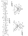
- a first embodiment of a device for treating one or more elongated elements such as wires 1, tubes, strips or profiles, metallic, made of glass fibers or any other material, successively comprises preferably a preheating station 2, a processing station for the elongated element 3, for example for the application of an advantageously insulating protective coating 4, and a cooling station symbolized at 5.
- This treatment station is characterized according to the present invention in that it comprises at least one chute or hopper 6 with bottom 7 open at 8 over its entire length in the direction of passage of the elongate element 1, as illustrated in Figure 3.
- This device also comprises means 10 for supplying treatment fluid 4, in this case a powdery protective coating product such as a plasticizing product, for example polyvinyl chloride or a plastic paint, circulating the coating product. protector in a direction not parallel to the direction of passage of the elongated element 1, as can be seen in FIG. 2.
- a powdery protective coating product such as a plasticizing product, for example polyvinyl chloride or a plastic paint
- the protective coating product 4 may advantageously be a plasticizing product loaded with a powder, in particular mineral, such as alumina or the like, or simply a mineral powder such as alumina, or a liquid, these various coating products having either thermally, electrically insulating properties or anticorrosive or other properties.
- this coating product advantageously has adhesive properties on the elongated element 1.
- the circuit 11 for supplying treatment fluid 4 comprises, below the bottom 7 open at 8 of the hopper 6, a member 14 for receiving the protective coating product 4 falling out of the hopper 6 in order to allow recycling of the protective coating product 4 by any suitable means such as a pump, as seen in FIG. 2.
- the receiving member 14 may comprise a screen 15 for separating the particles of treatment fluid 4 physically modified by passing through the protective coating application station 3.
- the screen 15 can advantageously be at its inclined and / or vibrated surface to facilitate the separation of said physically modified product particles 4.
- the hopper 6 of the treatment station comprises three sections.
- a first section 6a of inclined wall to form a funnel receiving the treatment fluid 4 this first section 6a is extended in its lower part by a second elongated section of substantially constant section, itself extended by a third section 25 of inclined wall .
- the elongated element 1 is disposed substantially in the center of said second section 6b, which thus defines a zone for processing the wire 1 in which the treatment fluid 4 has a continuous and regular homogeneous circulation.
- heating means 22, 23 for holding or elevation in high temperature of each elongated element.
- These heating means 22, 23 are advantageously constituted by inductors, emitters of infrared radiation, or the like.
- the spacing of the heating means 22 and 23 can be different at each station in order to modulate the temperature of the elongated element 1., which makes it possible to obtain better flexibility in the treatment of the elongated element, with a view to obtaining a better quality, for example of the protective coating.
- the heating means 22, 23 of the protective coating application station 3 are preferably arranged outside of the hopper 6, thus the hopper is made of a material not sensitive to induction, such as synthetic materials. or the like. It should be noted in this regard that the inductors 22 and 23 may be constituted by plates as seen in Figures 2 and 3, - or bars with ferrite cores.
- the third section 25 with an inclined wall of the hopper 6 with adjustable opening 8 makes it possible to partially cut off the stream of treatment fluid 4 falling on either side of the elongated element 1 or of the group of elongated elements. 1 in order to direct it under said elongated element 1 so as to completely surround it as symbolized by the arrows F in FIG. 2.
- a second embodiment of a treatment station according to the invention of an elongated element comprises a hopper 46 for supplying a treatment fluid 4, with the bottom 47 open at 48 on its entire length in the direction of passage of the elongated element 1.
- the elongated element 1 is located below the opening 48 of the hopper, the treatment fluid 4 freely falling by gravity from said opening 48 around the elongated element 1, this fluid 4 being recovered in a receiving member 44, substantially identical to the receiving member 14 described above and forming part of means (not shown) d supply of treatment fluid 4, similar to the supply means 10 described above.
- this embodiment comprises two elements 43, 42 arranged on either side of the elongate element 1, below the opening 48 of the hopper, defining between them the zone of treatment of the elongated element.
- these elements 42 and 43 may be heating means, such as inductors or emitters of infrared radiation, for heating or keeping the elongated element 1 at a high temperature during its journey under the hopper 46 of treatment, or as the case of vibration emitters.
- elements 45 and 49 are arranged on at least part of the opening 48 of the hopper, on either side of the elongated element 1 and are located above the opening 48 of said hopper 46, and between the elongated element 1 and the receiving member 44, as shown in FIG. 4.
- these elements are either ultrasonic transmitters , or ionizing means, the effects of which and their role will be described later.
- the third embodiment of a treatment station for an elongated element similarly comprises the second embodiment, a hopper 46, a member 44 for receiving the treatment fluid 4, and elements 43, 42 placed on either side of the elongate element 1 under the opening 48 of the hopper 46.
- the station treatment does not include means 45 and 49.
- this embodiment is used when the treatment fluid is in the liquid state, in this case, the width of the opening 48 is determined to have a flow of fluid suitable treatment, the elements 42, 43 advantageously being means for heating or maintaining the high temperature of the elongate element 1 in at least part of the treatment station.
- the flow of treatment fluid 4 in a treatment zone is controlled and determined by the adjustable positions of the various elements 42, 43, 45, 49 active or not.
- a treatment station for an elongated element in accordance with the invention and described above, can be used either for cleaning, pickling the elongated element 1, or for the application of a protective coating product on said elongated element 1, or for the application of an adhesive product, hereinafter called "primer-adhesive", or also for the cooling of said elongated element 1 or generally for any treatment of an elongated element with a fluid.
- a suitable treatment fluid for example a pickling fluid in the case of a cleaning treatment station or a protective coating product in the case of a station application of a protective coating, and to have in the treatment zone of the elongated element 1 elements 42, 43, 45, 49 or 22, 23 suitable.
- the wire 1 being for example wound on a basket or a support, this wire is unwound for example at a speed varying according to the various operating parameters such as the ambient temperature, the diameter of the wire, the melting temperature of the protective coating product used, in a reeling unit shown diagrammatically at 61.
- the method and the device of the invention makes it possible to obtain a perfectly adherent plastic coating 25/100 mm thick on the metal wire with a diameter of 2 mm with a speed of unwinding and passage of the wire in the processing device varying between about 300 m / min and 400 m / min.
- the wire 1 is passed through a first degreasing and cleaning treatment station 62 to obtain a surface condition of the wire 1 in order to promote the adhesion of the protective coating. later applied.
- this cleaning treatment station 62 advantageously has a structure in accordance with the three embodiments described above and represented in FIGS. 1 to 5.
- the treatment fluid 4 used advantageously consisting of a pickling liquid flowing in a fluidized abrasive powder.
- the cleaning efficiency is ensured, in such a treatment station, in particular by the homogenization of the treatment fluid by the ultrasound, as well as the increase of the cavitation pressure by adjusting the frequency of the ultrasound in depending on the diameter of the wire to be treated.
- the effect of ultrasound is favored by the liquid and depending on the treatment, it may be advantageous to preheat and / or maintain the elongated element at a predetermined temperature in the treatment zone.
- the metal wire 1 is then advantageously dried by, for example, a forced air drying 63 ′ allowing in particular to remove all the dust deposited on the wire 1.
- the concentric forced air drying stations allow, in the case of small diameter wire to maintain it in the axis of the device.
- other means for holding the elongated element in the axis of the device without contact are provided to avoid any deflection of this element in the different treatment zones.
- the protective coating product is not itself self-adhesive, passing the wire 1 preheated or not in a processing station 64 for the application of an appropriate adhesive product.
- This treatment station can be in accordance with one of the three embodiments shown in FIGS. 1 to 5. However, it is possible to apply said adhesive product by electrostatic spraying on the wire, previously polarized.
- the heating of the metal wire 1 is carried out by induction at medium frequency or high frequency, or by emitters of infrared radiation constituted by the elements 22 and 23 as shown in FIG. 1.
- a smoke extractor at this preheating station 26.
- the temperature of the wire 1 is of the order of approximately 250 ° C., in the case where a protective coating consisting of polyvinyl chloride is applied.
- the metal wire or group of metal wires 1 After having passed through the preheating station 65, the metal wire or group of metal wires 1 passes through the treatment station 66 for the application of protective coating at a speed identical to the speed of unwinding of the wire.
- This treatment station which is the essential organ of the treatment device of the invention, in the case of the application of a protective coating on an elongated wire, has a of the structures shown in FIGS. 1 to 5.
- the treatment fluid 4 in this case the protective coating product, is circulated in a homogeneous and regular manner in a direction not parallel to the direction of passage of the elongated element in the area of application of said protective coating, which is defined according to the embodiment either by the hopper 6 or by the elements 42,43,45,49, in order to provide a continuous renewal of the coating product 4 all around the metal wire 1.
- the continuous circulation of the coating product 4 is carried out substantially perpendicular to the direction of passage of the elongated element 1, advantageously at a predetermined speed substantially constant by causing it to fall by gravity from the end 12 of the supply circuit 11 ( FIG. 2) through the area of application of protective coating on each metal wire 1 and beyond it as can be seen in FIGS. 2, 4 and 5.
- each metal wire 1 is maintained over at least part of its path in the area of application of protective coating, which makes it possible to increase the speed of passage of the wire.
- the purpose of this heating is to maintain or bring each metal wire 1 to a high temperature, this temperature being of course predetermined and which may be different from the temperature of the metal wire 1 before entering the protective coating application zone and after its passage in said zone.
- means 30 for preheating the pulverulent product 4 disposed on the supply circuit 11 see FIG. 2.
- the treatment fluid 4 advantageously collected falling from the treatment zone is collected, using the receiving member 14 which is recycled by the supply circuit 11 substantially at the top of the hopper 6 for a new passage. It should be noted that this recycling generally facilitates the maintenance of the aforementioned temperature of the treatment fluid 4.
- the stream of treatment fluid 4 falling from the treatment zone is purified in order, for example, to separate the particles of product physically modified therefrom by passage in the vicinity of the heated metal wire 1, said modified particles being collected in a separate tank (not shown) and of course not recycled.
- the circulation of the treatment fluid in the treatment area is advantageously homogenized and promoted, by ultrasonic emitters 42, 43, 45, 49 arranged in the vicinity of the element 1 and from the lower opening of the hopper.
- the coated metal wire 1 passes through a finishing station 67, 20 where it is kept at a high temperature by the heating means 22, 23, 42, 43 by varying the spacing of said inductors 22, 23, 42, 43 or emitters of infrared radiation, which further accelerates the operation of applying the coating rotec- p tor and to regulate the surface finish.
- this post also includes a smoke extractor 27.
- the metal wire coated with a finished surface state is cooled in a cooling station 5, 72 by placing it in a refrigerating fluid, for example thermoregulated, which can be any known refrigerated system, and advantageously the treatment method of the invention. .
- a refrigerating fluid for example thermoregulated, which can be any known refrigerated system, and advantageously the treatment method of the invention.
- the cooling system chosen must not limit the speed of passage of the wire 1 in the device.
- the coated wire is wound on a reel on baskets or supports in a winding unit 68, for example.
- the elongate element 1 is subjected over the entire path of the device, to a rotation about its longitudinal axis, illustrated by the arrow R, for example, essentially caused by an appropriate winding of the element. elongated 1 and by a possibly static reeling thereof.
- the hopper 6, 46 which is substantially vertical as described and illustrated in the figures, can also be in an inclined position, in particular at 45 °.
- the method and device according to the invention make it possible to achieve a reduction in the length of the complete installation. Indeed, one can obtain an adhesive protective coating with a complete device of about twenty meters in length instead of 60 meters compared to the devices previous, with significantly superior productive, qualitative and economic performances.
- the invention makes it possible to produce a homogeneous elongated wire treatment device making it possible to control the temperature of the wire for example by infrared temperature detectors 69, and the thickness of the coating deposited, by optical control 70, and thus automating the entire device by slaving by appropriate electronic devices the elements 22, 23, 42, 43, 45, 49 to obtain the desired speed of travel of the wire 1 as well as the desired thickness and quality of coating.
- the method and device of the present invention can use any treatment fluid, for example liquid or pulverulent, and adapt to all protective coating products and especially as mentioned previously to the self-adhesive powders , which allows to remove in this case the adhesive product deposition station, or primer-adhesive.
- any treatment fluid for example liquid or pulverulent
- the self-adhesive powders which allows to remove in this case the adhesive product deposition station, or primer-adhesive.
- the method and the device of the invention make it possible to treat elongated wires of any kind, for example metallic, made of glass fibers or other materials.
- the process and the device of the invention make it possible to use as protective coating plasticizers advantageously containing a mineral filler such as for example alumina, or a mineral powder, or a liquid thus making it possible to obtain a protective insulating coating also electrically, whether against corrosion or thermally or otherwise, by an appropriate determination of the temperature of the elongated element in the treatment zone, as well as a judicious choice of the different elements 22, 23, 42, 43, 45, 49 .
- a mineral filler such as for example alumina, or a mineral powder, or a liquid
Landscapes
- Life Sciences & Earth Sciences (AREA)
- Engineering & Computer Science (AREA)
- Wood Science & Technology (AREA)
- Application Of Or Painting With Fluid Materials (AREA)
- Coating Apparatus (AREA)
Applications Claiming Priority (5)
| Application Number | Priority Date | Filing Date | Title |
|---|---|---|---|
| FR8005342 | 1980-03-10 | ||
| FR8005342A FR2477433A1 (fr) | 1980-03-10 | 1980-03-10 | Procede et dispositif d'application d'un revetement protecteur isolant notamment sur des elements allonges metalliques tels que des fils, tubes ou feuillards, et elements allonges revetus |
| AU74908/81A AU7490881A (en) | 1980-03-10 | 1981-09-03 | Device for coating elongate elements |
| ZA816184A ZA816184B (en) | 1980-03-10 | 1981-09-07 | Method and device for processing elongate elements such as wires,tubes,straps or sections,particularly for applying a protective coating on such elongate elements and elongate elements thus coated |
| BR8105763A BR8105763A (pt) | 1980-03-10 | 1981-09-09 | Processo e dispositivo para tratameno de elementos alongados e os elementos alongados |
Publications (1)
| Publication Number | Publication Date |
|---|---|
| EP0035948A1 true EP0035948A1 (fr) | 1981-09-16 |
Family
ID=32913052
Family Applications (1)
| Application Number | Title | Priority Date | Filing Date |
|---|---|---|---|
| EP81400372A Withdrawn EP0035948A1 (fr) | 1980-03-10 | 1981-03-10 | Dispositif de traitement d'éléments allongés, tels que des fils, tubes, feuillards ou profilés, notamment pour l'application d'un revêtement protecteur |
Country Status (5)
| Country | Link |
|---|---|
| EP (1) | EP0035948A1 (enExample) |
| AU (1) | AU7490881A (enExample) |
| BR (1) | BR8105763A (enExample) |
| FR (1) | FR2477433A1 (enExample) |
| ZA (1) | ZA816184B (enExample) |
Citations (1)
| Publication number | Priority date | Publication date | Assignee | Title |
|---|---|---|---|---|
| FR1426803A (fr) * | 1964-03-25 | 1966-01-28 | United States Steel Corp | Procédé et appareil pour former un revêtement sur un corps de forme allongée |
Family Cites Families (5)
| Publication number | Priority date | Publication date | Assignee | Title |
|---|---|---|---|---|
| US3019126A (en) * | 1959-03-24 | 1962-01-30 | United States Steel Corp | Method and apparatus for coating metal strip and wire |
| US3299853A (en) * | 1964-01-16 | 1967-01-24 | Amsted Ind Inc | Apparatus for coating elongated objects |
| US3361111A (en) * | 1964-07-30 | 1968-01-02 | Minnesota Mining & Mfg | Apparatus for cooling articles with particulate material |
| FR1445887A (fr) * | 1964-08-27 | 1966-07-15 | Gen Motors Corp | Procédé de revêtement des fils ou objets similaires au moyen d'une matière thermoplastique |
| FR1488904A (fr) * | 1965-10-15 | 1967-07-13 | Anchor Post Prod | Procédé de revêtement de fils métalliques par une matière plastique |
-
1980
- 1980-03-10 FR FR8005342A patent/FR2477433A1/fr active Granted
-
1981
- 1981-03-10 EP EP81400372A patent/EP0035948A1/fr not_active Withdrawn
- 1981-09-03 AU AU74908/81A patent/AU7490881A/en not_active Abandoned
- 1981-09-07 ZA ZA816184A patent/ZA816184B/xx unknown
- 1981-09-09 BR BR8105763A patent/BR8105763A/pt unknown
Patent Citations (1)
| Publication number | Priority date | Publication date | Assignee | Title |
|---|---|---|---|---|
| FR1426803A (fr) * | 1964-03-25 | 1966-01-28 | United States Steel Corp | Procédé et appareil pour former un revêtement sur un corps de forme allongée |
Also Published As
| Publication number | Publication date |
|---|---|
| ZA816184B (en) | 1982-08-25 |
| BR8105763A (pt) | 1983-04-19 |
| AU7490881A (en) | 1983-03-10 |
| FR2477433A1 (fr) | 1981-09-11 |
| FR2477433B1 (enExample) | 1983-07-29 |
Similar Documents
| Publication | Publication Date | Title |
|---|---|---|
| EP0367661B1 (fr) | Procédé et dispositif de fabrication d'un fil ou d'un ruban formé de fibres de renforcement et d'une matière organique thermoplastique | |
| EP0561720B1 (fr) | Procédé et appareil de traitement de particules | |
| FR2687095A1 (fr) | Procede de fabrication d'un fil composite et produits composites obtenus a partir dudit fil. | |
| FR2516441A1 (fr) | Procede de fabrication de profiles en resine thermoplastique chargee de fibres, installation pour la mise en oeuvre, profiles obtenus et leur utilisation | |
| EP0579821B1 (fr) | Dispositif de gainage d'un materiau filiforme par une matiere a l'etat fondu | |
| CH653602A5 (fr) | Procede et installation pour redensifier des dechets de mousse de resine thermoplastique. | |
| EP0273812A1 (fr) | Procédé et dispositif de fabrication d'un fil de verre simple obtenu directement sous filière | |
| FR2602226A1 (fr) | Equipement pour l'application d'email sous forme granulaire sur des carreaux a haute temperature | |
| EP0035948A1 (fr) | Dispositif de traitement d'éléments allongés, tels que des fils, tubes, feuillards ou profilés, notamment pour l'application d'un revêtement protecteur | |
| EP1230425A1 (fr) | Procede et dispositif d'application d'un revetement anti-corrosion | |
| EP0963260A1 (fr) | Procede et machine d'encollage superficiel de pieces souples a surface poreuse | |
| EP0956909B1 (fr) | Procédé et dispositif pour l'application électrostatique en continu d'une substance en poudre sur un substrat | |
| EP0027777A1 (fr) | Procédé et dispositif pour fabriquer simultanément une pluralité de filaments par voie électrostatique et application du procédé à la fabrication de produits non tissés et de revêtements | |
| FR2628014A1 (fr) | Procede et dispositif pour enrober des particules solides d'un film continu d'une matiere protectrice | |
| EP0200700A2 (fr) | Procédé de revêtement d'un support par une couche continue de granulats et installation pour la mise en oeuvre de ce procédé | |
| MC649A1 (fr) | Procédé et installation pour la fabrication de produits en matière synthétique avec produits de charge répartis dans la masse ainsi que produits conformes à ceux obtenus | |
| BE897613A (fr) | Procede et appareil en vue d'appliquer une poudre finement divisee sur une tole metallique | |
| EP0077733B1 (fr) | Procédé de préparation de matériaux composés de fibres de carbone et d'une matière thermoplastique, lesdits matériaux et leurs applications | |
| BE906117A (fr) | Procede de fabrication d'un support revetu de granulat, installation pour la mise en oeuvre du procede et support revetu. | |
| EP1144745B1 (fr) | Procede de fabrication d'un mat et produits obtenus | |
| EP0403002B1 (fr) | Procédé de poudrage électrostatique en vue de revêtir un objet de particules pulvérulentes ou granuleuses, et dispositif pour la mise en oeuvre de ce procédé | |
| FR2627404A1 (fr) | Procede et dispositif pour enrober des particules solides d'un film continu d'une matiere protectrice | |
| FR2653701A1 (fr) | Procede d'application d'une couche en matiere plastique sur un conducteur metallique. | |
| FR2784931A1 (fr) | Procede de fabrication d'un ruban composite forme de fibres de renforcement et de matiere organique thermoplastique | |
| JPH06206246A (ja) | 押出しにより細長い物体を被覆するための方法及び装置 |
Legal Events
| Date | Code | Title | Description |
|---|---|---|---|
| PUAI | Public reference made under article 153(3) epc to a published international application that has entered the european phase |
Free format text: ORIGINAL CODE: 0009012 |
|
| AK | Designated contracting states |
Designated state(s): AT BE DE FR GB IT SE |
|
| 17P | Request for examination filed |
Effective date: 19820310 |
|
| STAA | Information on the status of an ep patent application or granted ep patent |
Free format text: STATUS: THE APPLICATION IS DEEMED TO BE WITHDRAWN |
|
| 18D | Application deemed to be withdrawn |
Effective date: 19861001 |