EP0035934B1 - Bande d'éléments de contact à tenue en rive pour dispositif de connexion, et procédé de mise en oeuvre de tels éléments de contact - Google Patents
Bande d'éléments de contact à tenue en rive pour dispositif de connexion, et procédé de mise en oeuvre de tels éléments de contact Download PDFInfo
- Publication number
- EP0035934B1 EP0035934B1 EP81400321A EP81400321A EP0035934B1 EP 0035934 B1 EP0035934 B1 EP 0035934B1 EP 81400321 A EP81400321 A EP 81400321A EP 81400321 A EP81400321 A EP 81400321A EP 0035934 B1 EP0035934 B1 EP 0035934B1
- Authority
- EP
- European Patent Office
- Prior art keywords
- contact
- edge member
- apex
- contact elements
- edge
- Prior art date
- Legal status (The legal status is an assumption and is not a legal conclusion. Google has not performed a legal analysis and makes no representation as to the accuracy of the status listed.)
- Expired
Links
Images

Classifications
-
- H—ELECTRICITY
- H01—ELECTRIC ELEMENTS
- H01R—ELECTRICALLY-CONDUCTIVE CONNECTIONS; STRUCTURAL ASSOCIATIONS OF A PLURALITY OF MUTUALLY-INSULATED ELECTRICAL CONNECTING ELEMENTS; COUPLING DEVICES; CURRENT COLLECTORS
- H01R43/00—Apparatus or processes specially adapted for manufacturing, assembling, maintaining, or repairing of line connectors or current collectors or for joining electric conductors
- H01R43/16—Apparatus or processes specially adapted for manufacturing, assembling, maintaining, or repairing of line connectors or current collectors or for joining electric conductors for manufacturing contact members, e.g. by punching and by bending
Definitions
- the present invention relates to the field of electrically conductive contact elements used for the connection of electrical circuits, either in connectors, where they are housed in supports made of insulating material, or individually by implantation in circuits on cards, through apertures of suitable diameter.
- Such contact elements have an overall structure consisting of a front part, the function of which is to ensure electrical contact with another external element, a middle part usually carrying fastening elements such as pins or hooks, and a rear part, terminal or "contact tail", for connection with the wires or wiring elements of the circuits to be connected.
- the number presentation best suited for feeding the implantation machine is the fixing of the contact elements on a continuous strip, most often by their posterior end, or contact tail, constituting a temporary support from where they are detached at the time of implantation.
- a frequent embodiment is to constitute, from the same metallic material, the contact elements and the support strip where they are fixed, the separation operation being done by breaking a previously thinned part of the tail by which the contact is fixed on the support strip.
- the assembly is then in the form of a thin and flexible metal band, often called a "bank", on one side of which, in a comb arrangement, a plurality of contact elements are fixed by their shanks, these elements being obtained by cutting using a punch.
- This mode of presentation is advantageous in that it allows the global application to contacts of all manufacturing treatment operations, such as electroplating, for example, as well as their storage and then their implantation, by keeping them on the support strand. rolled on mandrel.
- the contact element is then implanted, either by mounting in a connector body, or directly by mounting in a circuit on a card.
- connection with the wiring wire of the equipment is carried out for example by winding ("wrapping").
- the thinned part of the tail participates in a first function, that of the fixing of the contact element. . It is therefore highly desirable that the thinning is limited to a value which retains a high resistance to folding, in order to avoid at this point any risk of deformation, which may even lead to untimely separation of certain elements.
- the thinned part assumes, after the contact separation operation, a second function, that of the guide tip for mounting and winding, a function which requires thinning a shape allowing the realization of a acute point, in the shape of a pyramid with negligible truncation.
- this condition is contradictory with the first, because it leads to adopt a significant thinning with all the disadvantages explained above, while, from the first function of it, it follows the need to adopt for him a very moderate, but leading, in a harmful way, after detachment of the contact, to a point in the shape of a strongly truncated pyramid, totally unsuitable for the role of guide to the introduction of which the need was shown above.
- the edge-held contact strip forming the object of the present invention does not have these drawbacks.
- the thinning of the contact tail assumes only the second, that is to say the realization of the tip, the contact fixing function being assumed by separate means independent of the thinning .
- This separation of functions provides the simultaneous possibility of a robust fixing of the contact on the shore during all handling operations, chemical and electroplating treatments, and the creation of a pyramid-shaped tip with very low truncation.
- the invention relates to a strip of contacts held at the edge for a connection device, comprising a support constituting the edge, in the form of a ribbon, and a plurality of contact elements in the form of a bar with rectangular section, fixed by one of their ends on one of the ribs of the shore by a fixing means, in a comb arrangement, the shore, the elements and their fixing means being made of the same continuous electrically conductive material, characterized in that said fixing means consists of a bar arranged perpendicular to the axis of the bar along two symmetrical wings, and of a U-shaped stirrup whose common base of the branches is supported by the bank, the respective ends of the wings and of the branches being connected together , and said bar having a triangle-shaped section whose apex is oriented opposite said common base the space enclosed between on the one hand, said apex and on the other hand, the s branches and the base of the stirrup being either open or occupied by a thin metal wall.
- the invention also relates to a method of implementing such a contact element.
- FIG. 1 represents a first embodiment, according to the prior art, of a strip of contacts held on the bank.
- It consists of a support 1 or "strand", and a plurality of contact elements 2 of rectangular section, one side of the rectangle 3 being parallel to the plane of the strand.
- the holding region 4 is of smaller section, and is connected with the contact and its support by two pyramids 5 and 6; that which is situated on the contact side constitutes, after separation as shown in (b), the insertion point.
- the pyramid is fully formed during the manufacture of the contact and it is connected to the bank only by the tip of the pyramid.
- the contacts are separated from the edge by "breaking", obtained for example by an oscillating movement either of the contacts or of the edge, or by shearing.
- FIG. 2 shows two views in elevation, in two perpendicular directions corresponding to the sides of the contact section rectangle, of the contact tip obtained by this first mode.
- this point has the shape of a truncated pyramid 20, the truncation surface 21 of which is large if it is desired to overcome the drawbacks described above in detail.
- this truncation for a pyramid with an angle at the top of 40 ° is a square with a side of 0.4 mm.
- FIG. 3 represents a second embodiment according to the prior art, of a contact strip where the edge holding region comprises a pair of inclined planes.
- the holding region has two inclined planes 31 and 32 constituting a dihedral whose edge is parallel to the plane of the shore; it can be obtained by striking during cutting, in the thickness of the metal of the edge.
- FIG. 4 shows two views in elevation, in two perpendicular directions, of the contact tip obtained by the second known mode, illustrated in FIG. 3.
- the separation of the contact by cutting, perpendicular to the plane of the edge, with a V-shaped tool makes it possible to adopt, without seeking mechanical resistance, a smaller dimension, in the direction perpendicular to the plane of the edge .
- this truncation is in the direction parallel to the shore, 0.3 mm for an angle at the top of the dihedron of 40 °, and, in the perpendicular direction, where it affects the shape of a portion of cylinder 42, with a diameter of 0.3 mm, for an angle of the two corresponding faces of the pyramid of 40 °.
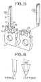
- FIG. 5 represents an embodiment of a strip of contacts held at the edge according to the invention, in two parts (a) (b) corresponding respectively to the strip before and after separation of the contact.
- the contact element 2 is fixed to the bank 1 by means entirely independent of those which define the point to be produced. It is therefore easy on the one hand to impart to the holding on the shore, all of the qualities of robustness whose need was mentioned above in detail, and on the other hand to impart to the tip of the contact a form to truncation as reduced as the striking and cutting processes allow.
- This arrangement thus advantageously transfers the support function to means arranged outside the region of the tip, with the possibility of giving them dimensions adapted to the need for robustness indicated above.
- the realization of the tip is obtained in two stages.
- the first is materialized as soon as it is produced by striking, along a dihedral with two inclined planes 55 and 56, the edge 57 of which is parallel to the plane of the bank 1.
- it is easy to produce , without limitations, a dihedral with reduced truncation, which can go, as shown in FIG. 5, to a sharp edge, with an opening such as 58.
- V-shaped cutout 59 In the direction perpendicular to the plane of the shore, the V-shaped cutout 59, represented in part (b), ensures that, as in the case of the known art of FIG. 4, the separation a point with truncation reduced to a portion of cylinder.
- FIG. 6 represents two views in elevation, in two perpendicular directions, of the contact tip obtained according to the invention.
- the pyramid made with a V-shaped cutting tool has a portion shape of cylinder of small radius.
- the residual truncation has a dimension, in the direction parallel to the shore, of less than 0.15 mm, for an apex angle of 40 °, and in the other affects the shape of a portion of cylinder with a radius of less than 0.15 mm, dimensions considerably smaller than those of the contacts according to the known art.
- the invention uses two lateral wings leaving, as shown in FIG. 5 at 58, an interval with the base 54 of the U-shaped support.
Landscapes
- Engineering & Computer Science (AREA)
- Manufacturing & Machinery (AREA)
- Manufacturing Of Electrical Connectors (AREA)
Applications Claiming Priority (2)
| Application Number | Priority Date | Filing Date | Title |
|---|---|---|---|
| FR8005203 | 1980-03-07 | ||
| FR8005203A FR2477786A1 (fr) | 1980-03-07 | 1980-03-07 | Bande d'elements de contact a tenue en rive pour dispositif de connexion et procede de mise en oeuvre de tels elements de contact |
Publications (2)
| Publication Number | Publication Date |
|---|---|
| EP0035934A1 EP0035934A1 (fr) | 1981-09-16 |
| EP0035934B1 true EP0035934B1 (fr) | 1984-02-15 |
Family
ID=9239457
Family Applications (1)
| Application Number | Title | Priority Date | Filing Date |
|---|---|---|---|
| EP81400321A Expired EP0035934B1 (fr) | 1980-03-07 | 1981-03-02 | Bande d'éléments de contact à tenue en rive pour dispositif de connexion, et procédé de mise en oeuvre de tels éléments de contact |
Country Status (5)
| Country | Link |
|---|---|
| US (1) | US4395087A (cg-RX-API-DMAC7.html) |
| EP (1) | EP0035934B1 (cg-RX-API-DMAC7.html) |
| CA (1) | CA1150380A (cg-RX-API-DMAC7.html) |
| DE (1) | DE3162196D1 (cg-RX-API-DMAC7.html) |
| FR (1) | FR2477786A1 (cg-RX-API-DMAC7.html) |
Families Citing this family (13)
| Publication number | Priority date | Publication date | Assignee | Title |
|---|---|---|---|---|
| GB8315211D0 (en) * | 1983-06-03 | 1983-07-06 | Molex Europ Management Ltd | Manufacturing moulded articles |
| IT1181253B (it) * | 1984-11-20 | 1987-09-23 | Arcotronics Italia Spa | Dispositivo per la recisione dei reofori di componenti elettrici e/o elettronici secondo un profilo prefissato |
| JPS62205653A (ja) * | 1986-03-06 | 1987-09-10 | Mitsui Haitetsuku:Kk | リ−ドフレ−ムおよび半導体装置の製造方法 |
| US4992056A (en) * | 1989-02-27 | 1991-02-12 | Amp Incorporated | Surface mount electrical connector and an electrical terminal therefor |
| US5240442A (en) * | 1991-05-17 | 1993-08-31 | Amp Incorporated | Electrical connector with posts having improved tip geometry |
| WO1994026006A1 (de) * | 1993-05-04 | 1994-11-10 | Vasile Ifrim | Verfahren zur herstellung einer spitze an einem kontaktstift |
| DE69426344T2 (de) * | 1993-09-14 | 2001-08-09 | Zierick Mfg. Corp., Mount Kisco | Oberflächenmontierter elektrischer Verbinder |
| GB2298530A (en) * | 1995-02-28 | 1996-09-04 | Zierick Mfg Corp | Surface mount electrical contacts |
| GB2298529A (en) * | 1995-02-28 | 1996-09-04 | Zierick Mfg Corp | Surface mount electrical tabs |
| US5816868A (en) * | 1996-02-12 | 1998-10-06 | Zierick Manufacturing Corp. | Capillary action promoting surface mount connectors |
| US6620002B1 (en) * | 2002-07-03 | 2003-09-16 | Hon Hai Precision Ind. Co., Ltd. | Contact strip for electrical connector |
| TW565025U (en) * | 2003-01-22 | 2003-12-01 | Speed Tech Corp | Connector terminal structure |
| JP2012064506A (ja) * | 2010-09-17 | 2012-03-29 | Yazaki Corp | 連鎖端子 |
Citations (3)
| Publication number | Priority date | Publication date | Assignee | Title |
|---|---|---|---|---|
| US3975072A (en) * | 1974-04-15 | 1976-08-17 | Elfab Corporation | Low profile integrated circuit connector and method |
| FR2386916A1 (fr) * | 1977-04-08 | 1978-11-03 | Gen Motors Corp | Ensemble de bornes de contact electrique en forme de douille |
| FR2424689A1 (fr) * | 1978-04-28 | 1979-11-23 | Comatel | Perfectionnements apportes aux contacts a souder |
Family Cites Families (5)
| Publication number | Priority date | Publication date | Assignee | Title |
|---|---|---|---|---|
| US2995617A (en) * | 1958-11-03 | 1961-08-08 | Malco Mfg Co | Self-locking terminal |
| US3601890A (en) * | 1969-11-04 | 1971-08-31 | Federal Tool Eng Co | Method of and apparatus for fabricating contacts and assembling them in groups with connector blocks |
| US3795889A (en) * | 1972-06-05 | 1974-03-05 | Amp Inc | Pin and socket type electrical contact terminals |
| US4021095A (en) * | 1974-02-21 | 1977-05-03 | Amp Incorporated | Stacked carrier strip assembly |
| US4037915A (en) * | 1976-04-29 | 1977-07-26 | Comatel - Comptoir Europeen De Materiel Electronique | Electrical connector strips |
-
1980
- 1980-03-07 FR FR8005203A patent/FR2477786A1/fr active Granted
-
1981
- 1981-03-02 DE DE8181400321T patent/DE3162196D1/de not_active Expired
- 1981-03-02 EP EP81400321A patent/EP0035934B1/fr not_active Expired
- 1981-03-04 US US06/240,482 patent/US4395087A/en not_active Expired - Fee Related
- 1981-03-05 CA CA000372375A patent/CA1150380A/en not_active Expired
Patent Citations (3)
| Publication number | Priority date | Publication date | Assignee | Title |
|---|---|---|---|---|
| US3975072A (en) * | 1974-04-15 | 1976-08-17 | Elfab Corporation | Low profile integrated circuit connector and method |
| FR2386916A1 (fr) * | 1977-04-08 | 1978-11-03 | Gen Motors Corp | Ensemble de bornes de contact electrique en forme de douille |
| FR2424689A1 (fr) * | 1978-04-28 | 1979-11-23 | Comatel | Perfectionnements apportes aux contacts a souder |
Also Published As
| Publication number | Publication date |
|---|---|
| CA1150380A (en) | 1983-07-19 |
| FR2477786A1 (fr) | 1981-09-11 |
| US4395087A (en) | 1983-07-26 |
| DE3162196D1 (en) | 1984-03-22 |
| EP0035934A1 (fr) | 1981-09-16 |
| FR2477786B1 (cg-RX-API-DMAC7.html) | 1982-01-29 |
Similar Documents
| Publication | Publication Date | Title |
|---|---|---|
| EP0035934B1 (fr) | Bande d'éléments de contact à tenue en rive pour dispositif de connexion, et procédé de mise en oeuvre de tels éléments de contact | |
| EP1170824B1 (fr) | Procédé de fabrication d'une bande de lamelles de contact électrique et bande de lamelles de contact électrique | |
| EP1202299A1 (fr) | Dispositif d'accumulation d'énergie électrique constitué par enroulement de rubans superposés et procédé de fabrication | |
| FR2784238A1 (fr) | Ensemble electrique du type comprenant un dispositif de connexion relie a une gaine de blindage d'un cable | |
| US3896535A (en) | Contact terminal extraction tool | |
| EP2846412B1 (fr) | Connecteur électrique à effort d'insertion réduit | |
| EP0717420B1 (fr) | Procédé pour la réalisation d'une gaine de blindage sur un faisceau de conducteurs électriques, et faisceau ainsi obtenu | |
| CA2043580C (fr) | Procede pour relier un conducteur electrique a une broche d'un connecteur, et liaison electrique obtenue par mise en oeuvre de ce procede | |
| FR2782194A1 (fr) | Dispositif de connexion auto-denudant | |
| CN1530965A (zh) | 扁形电缆 | |
| FR2460553A1 (fr) | Organe de contact electrique | |
| EP1677317B1 (fr) | Outil, procédé et dispositif de fabrication de harnais électriques | |
| CA1296788C (fr) | Raccord pour connexion de zones de contact electrique en materiau a memoire de forme | |
| FR2503463A1 (fr) | Dispositif de connexion | |
| EP0545841B1 (fr) | Procédé de préparation de coupe et de pré-dénudage pour câble ou fil conducteur et appareil pour sa mise en oeuvre | |
| FR2819348A1 (fr) | Connexion autodenudante a fente convergente | |
| CN105594068B (zh) | 一种电触头及其制造方法 | |
| FR2475805A1 (fr) | Dispositif de decoupe de gaines pour plaques d'accumulateurs | |
| FR2805667A1 (fr) | Dispositif pour etablir une connexion electrique, notamment sur des gaines de blindage | |
| EP0099384B1 (fr) | Connecteur electrique plat a trois broches | |
| JPH0536458A (ja) | 部分めつきされたポストコンタクトの製造方法 | |
| EP3656439B1 (fr) | Sonde implantable | |
| FR2766018A1 (fr) | Dispositif de connection auto-denudant pour cables electriques multi-conducteurs et en particulier pour cables courant faible multi-paires a haut debit | |
| EP4233131A1 (fr) | Connecteur pour la connexion d'une terminaison electrique sur un circuit imprime, procedes d'assemblage correspondants | |
| FR2691296A1 (fr) | Câble coaxial à extrémité d'âme centrée, son procédé de réalisation, et dispositif pour la mise en Óoeuvre dudit procédé. |
Legal Events
| Date | Code | Title | Description |
|---|---|---|---|
| PUAI | Public reference made under article 153(3) epc to a published international application that has entered the european phase |
Free format text: ORIGINAL CODE: 0009012 |
|
| AK | Designated contracting states |
Designated state(s): BE DE GB IT NL |
|
| 17P | Request for examination filed |
Effective date: 19820206 |
|
| ITF | It: translation for a ep patent filed | ||
| GRAA | (expected) grant |
Free format text: ORIGINAL CODE: 0009210 |
|
| AK | Designated contracting states |
Designated state(s): BE DE GB IT NL |
|
| PGFP | Annual fee paid to national office [announced via postgrant information from national office to epo] |
Ref country code: DE Payment date: 19840316 Year of fee payment: 4 |
|
| REF | Corresponds to: |
Ref document number: 3162196 Country of ref document: DE Date of ref document: 19840322 |
|
| PGFP | Annual fee paid to national office [announced via postgrant information from national office to epo] |
Ref country code: BE Payment date: 19840331 Year of fee payment: 4 |
|
| PLBE | No opposition filed within time limit |
Free format text: ORIGINAL CODE: 0009261 |
|
| STAA | Information on the status of an ep patent application or granted ep patent |
Free format text: STATUS: NO OPPOSITION FILED WITHIN TIME LIMIT |
|
| 26N | No opposition filed | ||
| PGFP | Annual fee paid to national office [announced via postgrant information from national office to epo] |
Ref country code: NL Payment date: 19850220 Year of fee payment: 5 |
|
| PG25 | Lapsed in a contracting state [announced via postgrant information from national office to epo] |
Ref country code: NL Effective date: 19861001 |
|
| NLV4 | Nl: lapsed or anulled due to non-payment of the annual fee | ||
| BERE | Be: lapsed |
Owner name: SOCAPEX Effective date: 19880331 |
|
| GBPC | Gb: european patent ceased through non-payment of renewal fee | ||
| PG25 | Lapsed in a contracting state [announced via postgrant information from national office to epo] |
Ref country code: GB Free format text: LAPSE BECAUSE OF NON-PAYMENT OF DUE FEES Effective date: 19881118 |
|
| PG25 | Lapsed in a contracting state [announced via postgrant information from national office to epo] |
Ref country code: DE Effective date: 19881201 |
|
| PG25 | Lapsed in a contracting state [announced via postgrant information from national office to epo] |
Ref country code: BE Effective date: 19890331 |