EP0034860A1 - Verschlusspfropfen für Akkumulatoren mit einem aufklappbaren Deckel - Google Patents
Verschlusspfropfen für Akkumulatoren mit einem aufklappbaren Deckel Download PDFInfo
- Publication number
- EP0034860A1 EP0034860A1 EP81200177A EP81200177A EP0034860A1 EP 0034860 A1 EP0034860 A1 EP 0034860A1 EP 81200177 A EP81200177 A EP 81200177A EP 81200177 A EP81200177 A EP 81200177A EP 0034860 A1 EP0034860 A1 EP 0034860A1
- Authority
- EP
- European Patent Office
- Prior art keywords
- plug
- cover
- liquid
- accumulators
- tube
- Prior art date
- Legal status (The legal status is an assumption and is not a legal conclusion. Google has not performed a legal analysis and makes no representation as to the accuracy of the status listed.)
- Withdrawn
Links
- 239000007788 liquid Substances 0.000 claims description 19
- 239000007789 gas Substances 0.000 claims description 12
- 238000007789 sealing Methods 0.000 claims description 2
- 239000011148 porous material Substances 0.000 abstract description 4
- 101100327917 Caenorhabditis elegans chup-1 gene Proteins 0.000 description 4
- 239000011324 bead Substances 0.000 description 2
- 238000004880 explosion Methods 0.000 description 2
- 239000000463 material Substances 0.000 description 2
- 238000009529 body temperature measurement Methods 0.000 description 1
- 229910010293 ceramic material Inorganic materials 0.000 description 1
- 238000003780 insertion Methods 0.000 description 1
- 230000037431 insertion Effects 0.000 description 1
- 239000000289 melt material Substances 0.000 description 1
- 238000000034 method Methods 0.000 description 1
- 238000012544 monitoring process Methods 0.000 description 1
- 229920003023 plastic Polymers 0.000 description 1
- 239000004033 plastic Substances 0.000 description 1
- 229920002620 polyvinyl fluoride Polymers 0.000 description 1
- 230000000630 rising effect Effects 0.000 description 1
- HBMJWWWQQXIZIP-UHFFFAOYSA-N silicon carbide Chemical compound [Si+]#[C-] HBMJWWWQQXIZIP-UHFFFAOYSA-N 0.000 description 1
- 229910010271 silicon carbide Inorganic materials 0.000 description 1
- 229920001169 thermoplastic Polymers 0.000 description 1
- 239000004416 thermosoftening plastic Substances 0.000 description 1
- 239000012780 transparent material Substances 0.000 description 1
Images
Classifications
-
- H—ELECTRICITY
- H01—ELECTRIC ELEMENTS
- H01M—PROCESSES OR MEANS, e.g. BATTERIES, FOR THE DIRECT CONVERSION OF CHEMICAL ENERGY INTO ELECTRICAL ENERGY
- H01M10/00—Secondary cells; Manufacture thereof
- H01M10/42—Methods or arrangements for servicing or maintenance of secondary cells or secondary half-cells
- H01M10/48—Accumulators combined with arrangements for measuring, testing or indicating the condition of cells, e.g. the level or density of the electrolyte
- H01M10/484—Accumulators combined with arrangements for measuring, testing or indicating the condition of cells, e.g. the level or density of the electrolyte for measuring electrolyte level, electrolyte density or electrolyte conductivity
-
- H—ELECTRICITY
- H01—ELECTRIC ELEMENTS
- H01M—PROCESSES OR MEANS, e.g. BATTERIES, FOR THE DIRECT CONVERSION OF CHEMICAL ENERGY INTO ELECTRICAL ENERGY
- H01M50/00—Constructional details or processes of manufacture of the non-active parts of electrochemical cells other than fuel cells, e.g. hybrid cells
- H01M50/30—Arrangements for facilitating escape of gases
- H01M50/308—Detachable arrangements, e.g. detachable vent plugs or plug systems
-
- H—ELECTRICITY
- H01—ELECTRIC ELEMENTS
- H01M—PROCESSES OR MEANS, e.g. BATTERIES, FOR THE DIRECT CONVERSION OF CHEMICAL ENERGY INTO ELECTRICAL ENERGY
- H01M50/00—Constructional details or processes of manufacture of the non-active parts of electrochemical cells other than fuel cells, e.g. hybrid cells
- H01M50/30—Arrangements for facilitating escape of gases
- H01M50/383—Flame arresting or ignition-preventing means
-
- H—ELECTRICITY
- H01—ELECTRIC ELEMENTS
- H01M—PROCESSES OR MEANS, e.g. BATTERIES, FOR THE DIRECT CONVERSION OF CHEMICAL ENERGY INTO ELECTRICAL ENERGY
- H01M50/00—Constructional details or processes of manufacture of the non-active parts of electrochemical cells other than fuel cells, e.g. hybrid cells
- H01M50/30—Arrangements for facilitating escape of gases
- H01M50/394—Gas-pervious parts or elements
-
- Y—GENERAL TAGGING OF NEW TECHNOLOGICAL DEVELOPMENTS; GENERAL TAGGING OF CROSS-SECTIONAL TECHNOLOGIES SPANNING OVER SEVERAL SECTIONS OF THE IPC; TECHNICAL SUBJECTS COVERED BY FORMER USPC CROSS-REFERENCE ART COLLECTIONS [XRACs] AND DIGESTS
- Y02—TECHNOLOGIES OR APPLICATIONS FOR MITIGATION OR ADAPTATION AGAINST CLIMATE CHANGE
- Y02E—REDUCTION OF GREENHOUSE GAS [GHG] EMISSIONS, RELATED TO ENERGY GENERATION, TRANSMISSION OR DISTRIBUTION
- Y02E60/00—Enabling technologies; Technologies with a potential or indirect contribution to GHG emissions mitigation
- Y02E60/10—Energy storage using batteries
Definitions
- the present invention relates to a plug for accumulators, which has a lid attached to it with a hinge.
- This lid has openings for the passage of gases and can be opened for filling and / or removing liquids.
- Such a plug which, in addition to filling and removing liquids, also allows the liquid level in the cell to be determined without unscrewing the plug or opening the lid, has become known, for example, from Swiss Patent 452,623, in particular FIG. 4. Grafting with such a hinged lid thus allows substantial labor savings when monitoring and maintaining batteries.
- Patent 3'907'605 has become known to arrange a gas-permeable, porous body instead of the usual openings in the plug, which allows channel gas to pass through, but prevents a flame from kicking back due to the relatively long and thin channels that cool the gas.
- Silicon carbide, polyvinyl fluoride and other sintered or foamed materials are used as the material for the porous body.
- the porous body is firmly connected to the remaining parts of the plug, and it is therefore necessary to remove the plug when checking or when refilling the liquid in the cell concerned.
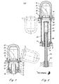
- FIG. 1 shows a longitudinal section through the first embodiment. It is a plug that allows the filling and removal of liquid and the temperature measurement without unscrewing.
- Figure 2 shows a longitudinal section through the second embodiment. It is a Grafting which, in addition to the properties of the first exemplary embodiment, also has features which indicate the level of the liquid.
- the plug shown in Fig. 1 has a cup 1 with a thread 2.
- the cup is preferably made of opaque plastic and is screwed into the cover 3 of a battery cell with the thread, with the insertion of a sealing ring 4.
- the cup 1 has in its interior a concentrically arranged tube 5 which penetrates the bottom of the cup and is fastened in the cup in a manner not shown in such a way that channels 6 are present between the pipe and the cup.
- the upper edge of the tube 5 lies below the edge of the cup.
- a cover 7 On the upper edge of the cup 1, a cover 7 is placed, which touches the inner wall of the cup on its outer wall and closes the interior of the cup and thus the interior of the cell in a gas-tight manner.
- the lid On its upper side, the lid carries two concentric annular beads 9 and 10. In the circular groove running between these two beads, the edge of a hood 11 made of porous, refractory or difficult to melt material is inserted and glued to the lid.
- the lid 7 is connected via a hinge 12 to a ring 13, this ring enclosing the outer edge of the cup 1.
- the ring, cover and hinge preferably consist of a single piece of thermoplastic, the hinge 12 being designed as a thin band. Thanks to this hinge, it is possible to lift the lid on the tongue 14 and put it in the ge dashed drawn position to spend. Then it is possible to take liquid samples with a hose inserted through the tube 5, to immerse a thermometer in the liquid or to fill in liquid.
- the holes 15 in the cover which are arranged outside the region of the opening of the tube 5, allow the oxyhydrogen gas formed when the cell is being charged to pass from the space below into the space above the cover.
- the gases flow through the porous hood 11 from the upper space and reach the surroundings. Liquid droplets entrained and rising through the tube 5 bounce off the cover and flow back through the channels 6 into the cell.
- the hood 11 is preferably made of a sintered ceramic material, but can also consist of another porous material known in connection with the intended use in question.
- the dimensions and the thickness of the hood must of course be such that, with the highest possible amount of gas being developed, the overpressure inside the hood is only small, so that the lid does not open. If such an opening were to occur, the entire protection against the backlash of flames into the cell space would of course be obsolete.
- the porous material can be attached in the form of a disc. It is also possible to combine the openings 15 into a single large opening in such a way that the cover 7 only forms one ring.
- the stopper according to FIG. 2 has the same cover as the stopper according to FIG. 1.
- the difference between the two stoppers is that the hollow cylinder 21 shown in FIG Mug.
- a tube 22 which has almost the length of the hollow cylinder.
- a further movable tube 23 which carries a float 24 floating on the liquid in the cell at the lower end.
- the tube 23 has a colored ring 25.
- the hollow cylinder 21 and the tube 22 are made of transparent material, so that the ring 25, which indicates the position of the float and thus the level of the liquid, is visible from the outside and without opening the lid.
- the movement of the tube 23 is limited on both sides by the closure 27 of the tube 22, which has an opening 26, and the shoulder 28.
Landscapes
- Chemical & Material Sciences (AREA)
- Chemical Kinetics & Catalysis (AREA)
- Electrochemistry (AREA)
- General Chemical & Material Sciences (AREA)
- Engineering & Computer Science (AREA)
- Manufacturing & Machinery (AREA)
- Filling, Topping-Up Batteries (AREA)
Abstract
An einem Akkumulatorpfropfen mit einem aufklappbaren Deckel (7) ist der Deckel (7) mit einer Haube (11) aus porösem, den Rückschlag von Flammen verhindernden Material abgeschlossen. Die Vorteile eines Pfropfens mit aufklappbarem Deckel und eines solchen mit einem den Rückschlag von Flammen hindernden Abschluss sind somit vereinigt.
Description
- Die vorliegende Erfindung betrifft einen Verschlusspfropfen für Akkumulatoren, welcher einen mit einem Scharnier daran befestigten Deckel aufweist. Dieser Deckel besitzt Oeffnungen zum Durchtritt von Gasen und ist zum Einfüllen und/oder Entnahme von Flüssigkeiten aufklappbar. Ein solcher Verschlusspfropfen, welcher neben dem Einfüllen und der Entnahme von Flüssigkeiten noch die Feststellung des Flüssigkeitsspiegels in der Zelle ohne Abschrauben des Pfropfens oder Oeffnen des Deckels erlaubt, ist beispielsweise aus der schweizerischen Patentschrift 452'623, insbesondere Figur 4, bekannt geworden. Pfropfen mit einem solchen aufklappbaren Deckel erlauben somit eine wesentliche Arbeitsersparnis bei der Ueberwachung und dem Unterhalt von Akkumulatoren.
- Da bei den Akkumulatoren gegen das Ende des Aufladevorgangs Knallgas durch die Oeffnungen des Pfropfens hindurch nach aussen abgegeben wird, besteht die Gefahr, dass sich dieses Gas irgendwo entzündet und die entstehende Flamme durch die genannten Oeffnungen hindurch in das Innere der betreffenden Zelle zurückschlägt und in dem oberhalb der Flüssigkeit befindlichen Raum der Zelle eine Explosion bewirkt. Um solchen Explosionen vorzubeugen, ist es beispielsweise aus der amerikanischen Patentschrift 3'907'605 bekannt geworden, anstelle von gewöhnlichen Oeffnungen im Pfropfen einen gasdurchlässigen, porösen Körper anzuordnen, welcher zwar Kanallgas durchtreten lässt, infolge der verhältnismässig langen und dünnen, das Gas abkühlenden Kanäle jedoch eine Flamme am Zurückschlagen hindert. Als Material für den porösen Körper werden Siliziumkarbid, Polyvinylfluorid und andere gesinterte oder geschäumte Materialien verwendet. Bei allen bekannten Pfropfen, welche mit einem Gasauslass aus porösem Material versehen sind, ist der poröse Körper mit den übrigen Teilen des Pfropfens fest verbunden, und es ist daher notwendig, bei der Ueberprüfung oder beim Nachfüllen der Flüssigkeit der betreffenden Zelle den Pfropfen zu entfernen.
- Dank der vorliegenden Erfindung ist es nun möglich, die Vorteile der Pfropfen mit einem aufklappbaren Deckel und der Pfropfen mit Mitteln zur Verhinderung des Uebertritts einer Flamme in das Innere der Zelle miteinander zu'kombinieren. Sie betrifft einen Verschlusspfropfen der eingangs beschriebenen Art, welcher durch die im kennzeichnenden Teil des Patentanspruchs angegebenen Merkmale gekennzeichnet ist.
- Die Erfindung wird nun anhand von zwei Ausführungsbeispielen erklärt.
- Die Figur 1 zeigt einen Längsschnitt durch das erste Ausführungsbeispiel. Es handelt sich dabei um einen Pfropfen, welcher das Auffüllen und die Entnahme von Flüssigkeit und die Temperaturmessung ohne Ausschrauben erlaubt.
- Die Figur 2 zeigt einen Längsschnitt durch das zweite Ausführungsbeispiel. Es handelt sich dabei um einen Pfropfen, welcher neben den Eigenschaften des ersten Ausführungsbeispiels noch Merkmale aufweist, welche die Höhe des Flüssigkeitsstandes erkennen lassen.
- Der in Fig. 1 dargestellte Pfropfen weist einen Becher 1 mit einem Gewinde 2 auf. Der Becher besteht vorzugsweise aus undurchsichtigem Kunststoff und ist mit dem Gewinde, unter Einfügung eines Dichtungsrings 4, in den Deckel 3 einer Akkumulatorzelle eingeschraubt. Der Becher 1 weist in seinem Innern ein konzentrisch angeordnetes Rohr 5 auf, das den Boden des Bechers durchdringt und in nicht dargestellter Weise im Becher derart befestigt ist, dass zwischen Rohr und Becher Kanäle 6 vorhanden sind. Der obere Rand des Rohrs 5 liegt unterhalb des Randes des Bechers.
- Auf den obern Rand des Bechers 1 ist ein Deckel 7 aufgesetzt, welcher auf seiner Aussenwand die Innenwand des Bechers berührt und den Innenraum des Bechers und damit den Innenraum der Zelle gasdicht abschliesst. Auf seiner oberen Seite trägt der Deckel zwei konzentrische ringförmige Wulste 9 und 10. In die zwischen diesen beiden Wulsten verlaufende kreisförmige Rinne ist der Rand einer Haube 11 aus porösem, feuerfestem oder schwer schmelzbarem Material eingesetzt und am Deckel angeklebt.
- Der Deckel 7 ist über ein Schranier 12 mit einem Ring 13 verbunden, wobei dieser Ring den äussern Rand des Bechers 1 umschliesst. Ring, Deckel und Scharnier bestehen vorzugsweise aus einem einzigen Stück Thermoplast, wobei das Scharnier 12 als dünnes Band ausgebildet ist. Dank diesem Scharnier ist es möglich, den Deckel an der Zunge 14 abzuheben und ihn in die gestrichelt gezeichnete Lage zu verbringen. Alsdann ist es möglich, mit einem durch das Rohr 5 hindurchgesteckten Schlauch Flüssigkeitsproben zu entnehmen, ein Thermometer in die Flüssigkeit zu tauchen oder Flüssigkeit einzufüllen.
- Die Löcher 15 im Deckel, welche aüsserhalb des Bereichs der Oeffnung des Rohrs 5 angeordnet sind, erlauben den Uebertritt des bei der Ladung der Zelle gebildeten Knallgases vom Raum unterhalb in den Raum oberhalb des Deckels. Vom obern Raum aus durchströmen die Gase die poröse Haube 11 und gelangen in die Umgebung. Mitgerissene und durch das Rohr 5 aufsteigende Flüssigkeitströpfchen prallen dabei am Deckel ab und fliessen durch die Kanäle 6 wieder in die Zelle zurück. Die Haube 11 besteht vorzugsweise aus einem gesinterten keramischen Material, kann aber auch aus einem andern im Zusammenhang mit dem in Frage stehenden Verwendungszweck bekannten porösen Material bestehen. Die Abmessungen und die Dicke der Haube müssen natürlich derart bemessen sein, dass bei der höchstmöglichen sich entwickelnden Gasmenge der Ueberdruck im Innern der Haube nur klein ist, so dass sich der Deckel nicht öffnet. Würde ein solches Oeffnen eintreten, wäre natürlich der ganze Schutz gegen das Zurückschlagen von Flammen in den Zellenraum hinfällig.
- Sofern der Pfropfen für eine kleine Zelle bestimmt ist, deren grösstmöglicher Ladestrom und damit auch die Gasentwicklung klein ist, kann das poröse Material in der Form einer Scheibe angebracht werden. Es ist auch möglich, die Oeffnungen 15 derart zu einer einzigen grossen Oeffnung zu vereinigen, dass der Deckel 7 nur noch einen Rinq bildet.
- Der Pfropfen gemäss Figur 2 weist einen gleichen Deckel auf wie der Pfropfen gemäss Figur 1. Der Unterschied zwischen den beiden Pfropfen liegt darin, dass bei dem in Figur 2 dargestellten anstelle des Bechers ein Hohlzylinder 21 vorhanden ist, dessen Länge wesentlich qrösser ist als diejenige des Bechers. Auch hier ist ein Rohr 22 vorhanden, welches nahezu die Länge des Hohlzylinders aufweist. Im Innern dieses Rohres 22 ist ein weiteres bewegliches Rohr 23 angebracht, welches am untern Ende einen auf der Flüssigkeit in der Zelle schwimmenden Schwimmer 24 trägt. Das Rohr 23 weist einen farbigen Ring 25 auf. Der Hohlzylinder 21 und das Rohr 22 sind aus durchsichtigem Material angefertigt, so dass der Ring 25, der die Lage des Schwimmers und damit den Stand der Flüssigkeit anzeigt, von aussen und ohne Offnen des Deckels sichtbar ist. Durch den eine Oeffnung 26 aufweisenden Verschluss 27 des Rohres 22 einerseits und durch den Absatz 28 ist die Bewegung des Rohres 23 beidseitig begrenzt.
- Nach dem Aufklappen des Deckels 7 ist es ohne das Entfernen des Pfropfens möglich, mit einem durch die Oeffnung 26 und die Rohre 22 und 25 hindurchgesteckten dünnen Saugschlauch eine Flüssigkeitsprobe zu entnehmen oder mit einem dünnen Thermometer die Temperatur der Flüssigkeit zu messen. Das Auffüllen von Flüssigkeit erfolgt durch Eingiessen in die Oeffnung des Hohlzylinders, worauf die Flüssigkeit zum Teil durch die Kanäle 6 und zum Teil durch die Rohre 22 und 23 fliesst. Am Ring 25 kann während des Füllens der Flüssigkeitsstand ständig beobachtet werden. t
Claims (1)
- Verschlusspfropfen für Akkumulatoren, mit einem mit einem Scharnier daran befestigten, zum Einfüllen und/oder zur Entnahme von Flüssigkeit aufklappbaren, Oeffnungen zum Durchtritt von Gasen aufweisenden Deckel, gekennzeichnet durch einen ausserhalb der genannten Oeffnungen (15) auf dem Deckel (7) angebrachten und diesen Teil des Deckels (7) gegenüber der Umgebung abschliessenden.gasdurchlässigen, jedoch den Durchtritt von Flammen verhindernden Körper (11), welcher von sämtlichen bei der Ladung des Akkumulators entstehenden und durch die genannten Oeffnungen tretenden Gase auf ihrem Weg in die Umgebung durchströmt wird.
Applications Claiming Priority (2)
| Application Number | Priority Date | Filing Date | Title |
|---|---|---|---|
| CH1430/80A CH653177A5 (de) | 1980-02-22 | 1980-02-22 | Verschlusspfropfen fuer akkumulatoren mit einem aufklappbaren deckel. |
| CH1430/80 | 1980-02-22 |
Publications (1)
| Publication Number | Publication Date |
|---|---|
| EP0034860A1 true EP0034860A1 (de) | 1981-09-02 |
Family
ID=4210277
Family Applications (1)
| Application Number | Title | Priority Date | Filing Date |
|---|---|---|---|
| EP81200177A Withdrawn EP0034860A1 (de) | 1980-02-22 | 1981-02-16 | Verschlusspfropfen für Akkumulatoren mit einem aufklappbaren Deckel |
Country Status (2)
| Country | Link |
|---|---|
| EP (1) | EP0034860A1 (de) |
| CH (1) | CH653177A5 (de) |
Cited By (2)
| Publication number | Priority date | Publication date | Assignee | Title |
|---|---|---|---|---|
| DE3232056A1 (de) * | 1982-08-28 | 1984-03-01 | CEAG Licht- und Stromversorgungstechnik GmbH, 4600 Dortmund | Batteriegehaeuse |
| EP0389769A1 (de) * | 1989-03-25 | 1990-10-03 | VARTA Batterie Aktiengesellschaft | Entgasungsstopfen für einen Bleiakkumulator |
Citations (4)
| Publication number | Priority date | Publication date | Assignee | Title |
|---|---|---|---|---|
| DE7133811U (de) * | 1973-02-08 | Bosch R Gmbh | Fahrzeug-Akkumulatoren-Batterie mit automatischer Wassernachfulleinnchtung | |
| FR2374748A1 (fr) * | 1976-12-20 | 1978-07-13 | Europ Accumulateurs | Obturateur pour orifice de remplissage d'un accumulateur electrique |
| DE7706828U1 (de) * | 1977-03-05 | 1978-08-31 | Varta Batterie Ag, 3000 Hannover | Verschlusstopfen fuer akkumulatoren |
| GB2016798A (en) * | 1978-03-15 | 1979-09-26 | Chloride Group Ltd | Vented filling plugs for electric storage cells |
-
1980
- 1980-02-22 CH CH1430/80A patent/CH653177A5/de not_active IP Right Cessation
-
1981
- 1981-02-16 EP EP81200177A patent/EP0034860A1/de not_active Withdrawn
Patent Citations (4)
| Publication number | Priority date | Publication date | Assignee | Title |
|---|---|---|---|---|
| DE7133811U (de) * | 1973-02-08 | Bosch R Gmbh | Fahrzeug-Akkumulatoren-Batterie mit automatischer Wassernachfulleinnchtung | |
| FR2374748A1 (fr) * | 1976-12-20 | 1978-07-13 | Europ Accumulateurs | Obturateur pour orifice de remplissage d'un accumulateur electrique |
| DE7706828U1 (de) * | 1977-03-05 | 1978-08-31 | Varta Batterie Ag, 3000 Hannover | Verschlusstopfen fuer akkumulatoren |
| GB2016798A (en) * | 1978-03-15 | 1979-09-26 | Chloride Group Ltd | Vented filling plugs for electric storage cells |
Cited By (2)
| Publication number | Priority date | Publication date | Assignee | Title |
|---|---|---|---|---|
| DE3232056A1 (de) * | 1982-08-28 | 1984-03-01 | CEAG Licht- und Stromversorgungstechnik GmbH, 4600 Dortmund | Batteriegehaeuse |
| EP0389769A1 (de) * | 1989-03-25 | 1990-10-03 | VARTA Batterie Aktiengesellschaft | Entgasungsstopfen für einen Bleiakkumulator |
Also Published As
| Publication number | Publication date |
|---|---|
| CH653177A5 (de) | 1985-12-13 |
Similar Documents
| Publication | Publication Date | Title |
|---|---|---|
| DE3843610A1 (de) | Trenn- oder reaktionssaeuleneinheit | |
| EP0226118B1 (de) | Behälter für aggressive Flüssigkeiten | |
| DE1115320B (de) | Akkumulatorenbehaelter | |
| EP0680104A1 (de) | Akkumulator mit Entgasungskanal | |
| EP0034860A1 (de) | Verschlusspfropfen für Akkumulatoren mit einem aufklappbaren Deckel | |
| EP0715891A1 (de) | Flasche, insbesondere für Standard-Lösungen | |
| EP0211160B1 (de) | Verfahren und Einrichtung zur nachprüfbaren Freisetzung von Gasen | |
| US3512648A (en) | Filtration column | |
| DE3825575A1 (de) | Absperrventil, insbesondere fuer gefaehrliche gase oder fluessigkeiten | |
| DE2558092C2 (de) | Keramikform zur Entnahme einer Probe aus einem blasenden Stahl-Konverter | |
| DE2734720C2 (de) | Trennröhrchen für die Zentrifugaltrennung | |
| DE19642238C1 (de) | Blei-Säure-Akkumulator mit Entgasungseinrichtung | |
| DE2249526C3 (de) | Leitfähigkeits-MeBzelle | |
| EP0468183A2 (de) | Probenbehältnis für die Entnahme von Gasproben und/oder Flüssigproben, insbesondere aus dem Sicherheitsbehälter eines Kernkraftwerks | |
| DE1227796B (de) | Nichtnachtropfender Giessverschluss fuer Flaschen und aehnliche Vorratsbehaelter | |
| DE1617511C3 (de) | Verschlußstopfen für Schott'sche Rollrandflaschen, Schott'sche Kulturflaschen und bakteriologische Reagenzgläser | |
| DE1404104C (de) | Isoherflasche | |
| DE2922208A1 (de) | Zentrifugenbehaelter | |
| DE1632687C (de) | Gasfeuerzeug | |
| DE588937C (de) | Verschluss fuer zusammendrueckbare Tuben | |
| AT153528B (de) | Brennstoffülleinrichtung für Feuerzeuge. | |
| DE867878C (de) | Sammlerbatterie | |
| DE2013102A1 (de) | Brennzunder fur Feststoffraketen | |
| DE2602427A1 (de) | Kartusche als brennstoffbehaelter | |
| DE7438680U (de) | Filtervorrichtung zum Trennen von Blutfraktionen |
Legal Events
| Date | Code | Title | Description |
|---|---|---|---|
| PUAI | Public reference made under article 153(3) epc to a published international application that has entered the european phase |
Free format text: ORIGINAL CODE: 0009012 |
|
| AK | Designated contracting states |
Designated state(s): AT BE CH DE FR GB IT LU NL SE |
|
| 17P | Request for examination filed |
Effective date: 19810810 |
|
| STAA | Information on the status of an ep patent application or granted ep patent |
Free format text: STATUS: THE APPLICATION IS DEEMED TO BE WITHDRAWN |
|
| 18D | Application deemed to be withdrawn |
Effective date: 19830111 |
|
| RIN1 | Information on inventor provided before grant (corrected) |
Inventor name: AUSDERAU, ALBERT |