EP0034082A2 - Vorrichtung zur Alarmauslösung im Falle eines ungenügenden Übertragungspegels für den Empfängermodul eines Übertragungssystems mit optischen Fasern - Google Patents
Vorrichtung zur Alarmauslösung im Falle eines ungenügenden Übertragungspegels für den Empfängermodul eines Übertragungssystems mit optischen Fasern Download PDFInfo
- Publication number
- EP0034082A2 EP0034082A2 EP81400109A EP81400109A EP0034082A2 EP 0034082 A2 EP0034082 A2 EP 0034082A2 EP 81400109 A EP81400109 A EP 81400109A EP 81400109 A EP81400109 A EP 81400109A EP 0034082 A2 EP0034082 A2 EP 0034082A2
- Authority
- EP
- European Patent Office
- Prior art keywords
- output
- alarm triggering
- filter
- amplifier
- triggering device
- Prior art date
- Legal status (The legal status is an assumption and is not a legal conclusion. Google has not performed a legal analysis and makes no representation as to the accuracy of the status listed.)
- Granted
Links
Images

Classifications
-
- H—ELECTRICITY
- H04—ELECTRIC COMMUNICATION TECHNIQUE
- H04B—TRANSMISSION
- H04B10/00—Transmission systems employing electromagnetic waves other than radio-waves, e.g. infrared, visible or ultraviolet light, or employing corpuscular radiation, e.g. quantum communication
- H04B10/60—Receivers
- H04B10/66—Non-coherent receivers, e.g. using direct detection
- H04B10/69—Electrical arrangements in the receiver
- H04B10/691—Arrangements for optimizing the photodetector in the receiver
- H04B10/6911—Photodiode bias control, e.g. for compensating temperature variations
Definitions
- the present invention relates generally to optical fiber transmission systems and relates more particularly to an alarm triggering device for an insufficient level of transmission on the line, for receiver module of a simplified transmission system for single fiber bond.
- a fiber optic transmission system consists of a transmitter module, a receiver module and a fiber arranged between these modules.
- the transmitter module comprises a transmitter base consisting of a laser diode, a control photodiode and a laser-fiber coupling optic inserted in a connector plug for the connection of said base to the fiber optic cable, and a control electronics ensuring inter alia regulation of the optical power emitted.
- the receiver module includes a detector base consisting of a photodetector, such as an avalanche photodiode, and a photodiode-fiber coupling optic inserted in a connector plug for the connection of said base to the fiber optic cable, and control electronics ensuring inter alia automatic gain regulation of the avalanche photodiode.
- the passband of the filter is external to the frequency band used for transmission over optical fiber.
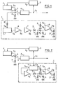
- the alarm triggering device 1 is connected at A to a photodetector, such as for example an avalanche photodiode 2, provided in the receiver module a transmission system using a single optical fiber.
- a photodetector such as for example an avalanche photodiode 2
- the input E of an amplifier A is connected at A to the avalanche photodiode 2, and said amplifier A delivers at output s 1 pulses having an amplitude, for example, of 1 volt peak to peak.
- a peak-to-peak detector 3 On the output S 1 of the amplifier A I is connected a peak-to-peak detector 3 ensuring the automatic gain regulation of the avalanche photodiode 2, and whose output S 2 is connected to a bias circuit 4 of the photodiode at avalanche 2, the output S 3 of this bias circuit being connected to said avalanche photodiode.
- the avalanche photodiode 2 is connected at A to earth via a resistor R.
- This alarm triggering device 1 comprises a filter 5, the input E4 of which is connected to the avalanche photodiode 2 by means of a resistor R 'whose value is clearly greater than that of the resistor R.
- the filter 5 has a passband external to the frequency band used for transmission by the pulse code. More specifically, the average frequency of filter 5 can be either lower (in this case, filter 5 is a low-pass filter), or higher (in this case, filter 5 is a high-pass filter) at the lower or higher of said frequency band used for transmission by the pulse code, respectively.
- the code used is for example the code 3B - 4B / 4E 6S6 OM which is described in the French patent application filed on December 18, 1979 in the name of the Applicant, concerning: “Process for transcoding binary information for transmission over line and trans system mission using it. "
- the output S 4 of the filter 5 is connected to a very low noise amplifier 6, the output S 5 of which is connected to an amplifier 7.
- a rectification circuit comprising a diode D and a resistor R 1 , and in series an integrator circuit comprising a resistor R 2 and a capacitor C.
- the output of this integrator circuit is connected to one of the input terminals E 8 of a threshold comparator amplifier 8, while that the other input terminal E 9 of said amplifier 8 is connected to an adjustable reference voltage source developed at 9.
- At the output S 8 of the comparator amplifier 8 are connected in series a resistor R 3 and a light-emitting diode By commanding an alarm.
- the diode D ′ can be replaced by any other suitable means without departing from the scope of the invention.
- the alarm triggering device 1 is connected to the output S 1 of the amplifier A 1 . More specifically, the input E4 of the filter 5 is connected to the output S 1 of the amplifier A and the output S4 of said filter 5 is directly connected to the input of amplifier 7.
- the alarm triggering device 1 described above is connected between the output S 1 of amplifier A and the bias circuit 4 of the avalanche photodiode 2. More precisely, the output S 8 of the comparator amplifier 8 is connected to the light-emitting diode D 'and to the input of the bias circuit 4. Thus, the automatic gain regulation of the avalanche photodiode 2 is ensured from the comparator amplifier 8.
- the coded electrical pulses produced by the avalanche photodiode 2 are amplified by the amplifier A and they have a constant amplitude at the exit thanks to a control loop.
- the peak-to-peak amplitude of the pulses is measured by the peak-to-peak detector 3 which therefore delivers a proportional direct voltage therefrom.
- This voltage is applied to the bias circuit 4 of the avalanche photodiode 2 and therefore controls the gain, said photodiode also having a temperature drift.
- this servo-control makes it possible to maintain the normalized constant amplitude (for example 1 volt peak to peak) of the output signals despite possible variations in ambient temperature and variations in the incident optical power.
- the servo system described above causes an overpolarization (with respect to normal polarization) of the avalanche photodiode 2 which therefore delivers, at the output of the noise, of the order for example of 1 volt.
- the principle of triggering an alarm lies in the fact that energy is used in an unused frequency band for the transmission of the pulse code; this is obtained by the filter 5, the pass band of which is outside the frequency band used by the pulse code.
- the noise is amplified by the first low noise amplifier 6 and by the second amplifier 7, then rectified by the rectification circuit (D and R 1 ), and integrated by the integrator circuit ( R 2 and C), so as to produce a direct voltage proportional to the effective value of the noise.
- This voltage is then compared to a reference voltage developed at 9, by the amplifier 8. If this threshold voltage is reached, the comparator amplifier 8 supplies a control signal to the light emitting diode Triggering an alarm of any kind.
- the adjustment of said reference voltage makes it possible to determine the minimum alarm optical power; for example, the standard power being - 53 dBm, the alarm power is - 60 dBm.
- the alarm triggering device also has the function of ensuring the automatic gain regulation of the avalanche photodiode.
Landscapes
- Physics & Mathematics (AREA)
- Electromagnetism (AREA)
- Engineering & Computer Science (AREA)
- Computer Networks & Wireless Communication (AREA)
- Signal Processing (AREA)
- Optical Communication System (AREA)
- Light Receiving Elements (AREA)
Applications Claiming Priority (2)
| Application Number | Priority Date | Filing Date | Title |
|---|---|---|---|
| FR8003047 | 1980-02-12 | ||
| FR8003047A FR2475826A1 (fr) | 1980-02-12 | 1980-02-12 | Dispositif de declenchement d'alarme pour une insuffisance du niveau de transmission, pour module recepteur d'un systeme de transmission sur fibre optique |
Publications (3)
| Publication Number | Publication Date |
|---|---|
| EP0034082A2 true EP0034082A2 (de) | 1981-08-19 |
| EP0034082A3 EP0034082A3 (en) | 1981-08-26 |
| EP0034082B1 EP0034082B1 (de) | 1983-11-23 |
Family
ID=9238485
Family Applications (1)
| Application Number | Title | Priority Date | Filing Date |
|---|---|---|---|
| EP81400109A Expired EP0034082B1 (de) | 1980-02-12 | 1981-01-27 | Vorrichtung zur Alarmauslösung im Falle eines ungenügenden Übertragungspegels für den Empfängermodul eines Übertragungssystems mit optischen Fasern |
Country Status (5)
| Country | Link |
|---|---|
| US (1) | US4399565A (de) |
| EP (1) | EP0034082B1 (de) |
| DE (1) | DE3161450D1 (de) |
| FR (1) | FR2475826A1 (de) |
| HU (1) | HU183317B (de) |
Cited By (1)
| Publication number | Priority date | Publication date | Assignee | Title |
|---|---|---|---|---|
| FR2563066A1 (fr) * | 1984-04-12 | 1985-10-18 | Ericsson Telefon Ab L M | Dispositif destine a augmenter la dynamique d'un recepteur optoelectrique integrateur |
Families Citing this family (16)
| Publication number | Priority date | Publication date | Assignee | Title |
|---|---|---|---|---|
| GB2101827B (en) * | 1981-07-07 | 1985-02-13 | Standard Telephones Cables Ltd | Optical receiver |
| JPS5824258A (ja) * | 1981-08-06 | 1983-02-14 | Sumitomo Electric Ind Ltd | 光通信受信回路 |
| US4556875A (en) * | 1981-12-15 | 1985-12-03 | Matsushita Electric Industrial Co., Ltd. | Irradiated power monitoring system for optical fiber |
| US5140636A (en) * | 1985-05-02 | 1992-08-18 | The United States Of America As Represented By The Secretary Of The Navy | Interferometric optical fiber data link |
| US4903339A (en) * | 1988-06-16 | 1990-02-20 | The United States Of America As Represented By The Director, National Security Agency | Locally nulled sine-wave total power alarm for intrusion detecting optical communications systems |
| US4882774A (en) * | 1988-08-25 | 1989-11-21 | Laser Communications, Inc. | Laser beam data verification system |
| EP0360877B1 (de) * | 1988-09-15 | 1994-12-07 | Siemens Aktiengesellschaft | Schaltungsanordnung zur Ermittlung einer empfangenen Lichtleistung |
| JPH02113640A (ja) * | 1988-10-21 | 1990-04-25 | Toshiba Corp | 自動利得制御装置 |
| US4947459A (en) * | 1988-11-25 | 1990-08-07 | Honeywell, Inc. | Fiber optic link noise measurement and optimization system |
| DK142496A (da) * | 1996-12-13 | 1998-06-14 | Dsc Communications As | Optisk modtager samt fremgangsmåde til beskyttelse af en sådan |
| JP3541781B2 (ja) * | 2000-05-26 | 2004-07-14 | 日本電気株式会社 | 信号入力断検出器、光受信器及び信号入力断検出方法 |
| JP3719119B2 (ja) * | 2000-09-27 | 2005-11-24 | 日本電気株式会社 | 光受信装置 |
| JP2003158493A (ja) * | 2001-11-21 | 2003-05-30 | Mitsubishi Electric Corp | 光遮断検出装置、光受信器、光送信器及び光遮断検出方法 |
| US7215883B1 (en) | 2003-01-24 | 2007-05-08 | Jds Uniphase Corporation | Methods for determining the performance, status, and advanced failure of optical communication channels |
| US7002131B1 (en) | 2003-01-24 | 2006-02-21 | Jds Uniphase Corporation | Methods, systems and apparatus for measuring average received optical power |
| US10345157B2 (en) * | 2014-04-16 | 2019-07-09 | Silicon Integrated Systems Corp. | On-chip temperature sensing device |
Citations (1)
| Publication number | Priority date | Publication date | Assignee | Title |
|---|---|---|---|---|
| DE2853353A1 (de) * | 1977-12-29 | 1979-07-05 | Sperry Rand Corp | Schaltungsanordnung zur aufbereitung von verstaerkten, urspruenglich digitalen daten |
Family Cites Families (1)
| Publication number | Priority date | Publication date | Assignee | Title |
|---|---|---|---|---|
| FR2361022A1 (fr) * | 1976-08-06 | 1978-03-03 | Aerospatiale | Procede et dispositif de transmission de signaux par fibres optiques |
-
1980
- 1980-02-12 FR FR8003047A patent/FR2475826A1/fr active Granted
-
1981
- 1981-01-27 DE DE8181400109T patent/DE3161450D1/de not_active Expired
- 1981-01-27 EP EP81400109A patent/EP0034082B1/de not_active Expired
- 1981-02-09 US US06/232,966 patent/US4399565A/en not_active Expired - Fee Related
- 1981-02-09 HU HU81310A patent/HU183317B/hu unknown
Patent Citations (1)
| Publication number | Priority date | Publication date | Assignee | Title |
|---|---|---|---|---|
| DE2853353A1 (de) * | 1977-12-29 | 1979-07-05 | Sperry Rand Corp | Schaltungsanordnung zur aufbereitung von verstaerkten, urspruenglich digitalen daten |
Cited By (3)
| Publication number | Priority date | Publication date | Assignee | Title |
|---|---|---|---|---|
| FR2563066A1 (fr) * | 1984-04-12 | 1985-10-18 | Ericsson Telefon Ab L M | Dispositif destine a augmenter la dynamique d'un recepteur optoelectrique integrateur |
| WO1985004773A1 (en) * | 1984-04-12 | 1985-10-24 | Telefonaktiebolaget Lm Ericsson | Apparatus for increasing the dynamic range in an integrating optoelectric receiver |
| GB2173966A (en) * | 1984-04-12 | 1986-10-22 | Ericsson Telefon Ab L M | Apparatus for increasing the dynamic range in an integrating optoelectric receiver |
Also Published As
| Publication number | Publication date |
|---|---|
| DE3161450D1 (en) | 1983-12-29 |
| EP0034082A3 (en) | 1981-08-26 |
| HU183317B (en) | 1984-04-28 |
| FR2475826A1 (fr) | 1981-08-14 |
| US4399565A (en) | 1983-08-16 |
| EP0034082B1 (de) | 1983-11-23 |
| FR2475826B1 (de) | 1982-10-01 |
Similar Documents
| Publication | Publication Date | Title |
|---|---|---|
| EP0034082B1 (de) | Vorrichtung zur Alarmauslösung im Falle eines ungenügenden Übertragungspegels für den Empfängermodul eines Übertragungssystems mit optischen Fasern | |
| EP0034957B1 (de) | Vorrichtung zur automatischen Regulierung der Ausgangsleistung eines Sendermoduls für ein Übertragungssystem mit optischen Fasern | |
| EP0052536B1 (de) | Sendermodul-Ausgangsleistungsstabilisierungsanordnung für ein Lichtwellenleiter-Übertragungssystem | |
| EP0583186B1 (de) | Vorrichtung zur Leistungsstabilisierung von Laserdioden | |
| EP0709254B1 (de) | Elektronisches Informationsübertragungssystem auf stromführenden Leitungen, insbesonders für ein Kraftfahrzeug | |
| FR2512298A1 (fr) | Systeme et methode de modulation de frequence optique | |
| FR2750552A1 (fr) | Recepteur pour systeme de transmission de signaux numeriques par voie optique | |
| FR2526554A1 (fr) | Procede de regulation de moyens emetteurs d'informations lumineuses et le systeme de mise en oeuvre | |
| FR2716984A1 (fr) | Procédé et dispositif pour empêcher l'apparition d'une surintensité lumineuse transitoire dans un amplificateur/émetteur optique. | |
| FR2756983A1 (fr) | Amplificateur optique et procede et dispositif de controle de gain d'amplificateur optique | |
| CA1266091A (fr) | Dispositif de telecommunication par fibres optiques | |
| FR2571148A1 (fr) | Detecteur de faisceau lumineux a photodiode a circuit de reglage du point de fonctionnement | |
| EP0247940B1 (de) | Überwachungsvorrichtung mit Lichtwellenleiter | |
| FR2520174A1 (fr) | Systeme de transmission de signaux numeriques sur fibre optique | |
| EP3248305B1 (de) | Ethernet-switch für faseroptisches netzwerk | |
| EP0106728A1 (de) | Verfahren und Vorrichtung zur Verstärkungsstabilisierung eines fotoempfindlichen Avalanche-Bauelements | |
| CA2306687A1 (fr) | Dispositif emetteur recepteur optronique a diaphotie reduite | |
| FR2532802A1 (fr) | Systeme de transmission d'informations comportant un dispositif de regulation des niveaux des informations | |
| FR2524230A1 (fr) | Systeme de transmission d'informations sur une voie de service du type fibre optique | |
| FR2500972A1 (fr) | Procede et dispositif de transmission de signaux analogiques rapides sur fibres optiques | |
| EP0027758A1 (de) | Einrichtung zur automatischen Verstärkungsregelung durch optische Mittel in einem System zur Übertragung elektrischer Signale über eine optische Strecke | |
| EP0560659A1 (de) | Verfahren und Vorrichtung zur optischen Übertragung eines Multiplexsignals mit elektrischen Trägern | |
| FR2513399A1 (fr) | Emetteur pour systeme de transmission sur fibre optique comportant un dispositif de stabilisation de la puissance optique emise | |
| FR2490404A1 (fr) | Procede et dispositif de stabilisation du gain d'une photodiode a avalanche | |
| EP0561692B1 (de) | Verfahren und Anordnung zur optischen Nachrichtenübertragung |
Legal Events
| Date | Code | Title | Description |
|---|---|---|---|
| PUAI | Public reference made under article 153(3) epc to a published international application that has entered the european phase |
Free format text: ORIGINAL CODE: 0009012 |
|
| PUAL | Search report despatched |
Free format text: ORIGINAL CODE: 0009013 |
|
| AK | Designated contracting states |
Designated state(s): BE CH DE GB IT NL |
|
| AK | Designated contracting states |
Designated state(s): BE CH DE GB IT NL |
|
| 17P | Request for examination filed |
Effective date: 19811119 |
|
| ITF | It: translation for a ep patent filed |
Owner name: JACOBACCI & PERANI S.P.A. |
|
| GRAA | (expected) grant |
Free format text: ORIGINAL CODE: 0009210 |
|
| AK | Designated contracting states |
Designated state(s): BE CH DE GB IT LI NL |
|
| REF | Corresponds to: |
Ref document number: 3161450 Country of ref document: DE Date of ref document: 19831229 |
|
| PLBE | No opposition filed within time limit |
Free format text: ORIGINAL CODE: 0009261 |
|
| STAA | Information on the status of an ep patent application or granted ep patent |
Free format text: STATUS: NO OPPOSITION FILED WITHIN TIME LIMIT |
|
| 26N | No opposition filed | ||
| PGFP | Annual fee paid to national office [announced via postgrant information from national office to epo] |
Ref country code: GB Payment date: 19930104 Year of fee payment: 13 |
|
| PGFP | Annual fee paid to national office [announced via postgrant information from national office to epo] |
Ref country code: CH Payment date: 19930120 Year of fee payment: 13 |
|
| ITTA | It: last paid annual fee | ||
| PGFP | Annual fee paid to national office [announced via postgrant information from national office to epo] |
Ref country code: NL Payment date: 19930131 Year of fee payment: 13 |
|
| PGFP | Annual fee paid to national office [announced via postgrant information from national office to epo] |
Ref country code: BE Payment date: 19930202 Year of fee payment: 13 |
|
| PGFP | Annual fee paid to national office [announced via postgrant information from national office to epo] |
Ref country code: DE Payment date: 19930217 Year of fee payment: 13 |
|
| PG25 | Lapsed in a contracting state [announced via postgrant information from national office to epo] |
Ref country code: GB Effective date: 19940127 |
|
| PG25 | Lapsed in a contracting state [announced via postgrant information from national office to epo] |
Ref country code: LI Effective date: 19940131 Ref country code: CH Effective date: 19940131 Ref country code: BE Effective date: 19940131 |
|
| BERE | Be: lapsed |
Owner name: LIGNES TELEGRAPHIQUES ET TELEPHONIQUES LTT Effective date: 19940131 |
|
| PG25 | Lapsed in a contracting state [announced via postgrant information from national office to epo] |
Ref country code: NL Effective date: 19940801 |
|
| NLV4 | Nl: lapsed or anulled due to non-payment of the annual fee | ||
| GBPC | Gb: european patent ceased through non-payment of renewal fee |
Effective date: 19940127 |
|
| REG | Reference to a national code |
Ref country code: CH Ref legal event code: PL |
|
| PG25 | Lapsed in a contracting state [announced via postgrant information from national office to epo] |
Ref country code: DE Effective date: 19941001 |