EP0033588A2 - Outil pour usiner des surfaces en forme de spirale - Google Patents
Outil pour usiner des surfaces en forme de spirale Download PDFInfo
- Publication number
- EP0033588A2 EP0033588A2 EP81300133A EP81300133A EP0033588A2 EP 0033588 A2 EP0033588 A2 EP 0033588A2 EP 81300133 A EP81300133 A EP 81300133A EP 81300133 A EP81300133 A EP 81300133A EP 0033588 A2 EP0033588 A2 EP 0033588A2
- Authority
- EP
- European Patent Office
- Prior art keywords
- platform
- socket
- tube
- tool
- cutter
- Prior art date
- Legal status (The legal status is an assumption and is not a legal conclusion. Google has not performed a legal analysis and makes no representation as to the accuracy of the status listed.)
- Withdrawn
Links
Images


Classifications
-
- B—PERFORMING OPERATIONS; TRANSPORTING
- B23—MACHINE TOOLS; METAL-WORKING NOT OTHERWISE PROVIDED FOR
- B23B—TURNING; BORING
- B23B3/00—General-purpose turning-machines or devices, e.g. centre lathes with feed rod and lead screw; Sets of turning-machines
- B23B3/22—Turning-machines or devices with rotary tool heads
- B23B3/26—Turning-machines or devices with rotary tool heads the tools of which perform a radial movement; Rotary tool heads thereof
- B23B3/265—Surfacing or grooving flanges
-
- B—PERFORMING OPERATIONS; TRANSPORTING
- B23—MACHINE TOOLS; METAL-WORKING NOT OTHERWISE PROVIDED FOR
- B23B—TURNING; BORING
- B23B5/00—Turning-machines or devices specially adapted for particular work; Accessories specially adapted therefor
- B23B5/16—Turning-machines or devices specially adapted for particular work; Accessories specially adapted therefor for bevelling, chamfering, or deburring the ends of bars or tubes
- B23B5/161—Devices attached to the workpiece
- B23B5/162—Devices attached to the workpiece with an internal clamping device
-
- Y—GENERAL TAGGING OF NEW TECHNOLOGICAL DEVELOPMENTS; GENERAL TAGGING OF CROSS-SECTIONAL TECHNOLOGIES SPANNING OVER SEVERAL SECTIONS OF THE IPC; TECHNICAL SUBJECTS COVERED BY FORMER USPC CROSS-REFERENCE ART COLLECTIONS [XRACs] AND DIGESTS
- Y10—TECHNICAL SUBJECTS COVERED BY FORMER USPC
- Y10T—TECHNICAL SUBJECTS COVERED BY FORMER US CLASSIFICATION
- Y10T82/00—Turning
- Y10T82/25—Lathe
- Y10T82/2522—Portable
Definitions
- the tool of this invention is especially adapted for carrying out cutting operations in the field on work members having greatly varied configurations.
- a tool for cutting a work member includes a base for fixedly supporting a hollow stationary tube.
- a circular platform is rotatably mounted on the tube.
- a socket is mounted on the face of the platform.
- a cutter is carried by the socket.
- a rotatable planetary shaft extends through the platform.
- Planetary means are coupled between the planetary shaft and the stationary tube for rotating the planetary shaft with the rotation of the platform.
- Transmission means couple a drive shaft to the planetary shaft and with the socket for simultaneously and synchronously moving the cutter in a linear radial direction relative to the center of the platform.
- the socket is movable on a tool box mounted on the drive shaft for adjustable pivotable rotation relative to the platform.
- a rod which is coaxially mounted within the tube.
- a clamp is coupled to the rod.
- a sleeve is concentrically mounted between the rod and the tube. The sleeve is attached to the clamp and is movable in a longitudinal direction to bring the clamp and the work member mounted thereon toward or away from the platform.
- Tool 10 has a base 9 and an upright frame 9a defining holes 9b through which a rope 9c ( Figure 19) can be attached.
- a motor 8 is mounted on frame 9a with its shaft 57 extending horizontally parallel to base 9.
- a cylindrical collar 78 mounts a main stationary support tube 7 on frame 9a. The axis of tube 7 extends in a horizontal direction.
- a circular platform 31 is rotatably mounted about tube 7.
- Platform 31 has a front face 33.
- a pulley 60 is secured to the back of platform 31 by gussets 31a.
- Platform 31 is rotatably mounted about tube 7 on roller bearings 32 held in place by a retainer ring 34.
- a cutter 50 is mounted in a socket 49 which rotates with platform 31. Rotating cutter 50 can be made to simultaneously linearly travel in a radial direction relative to the axis of face 33.
- the movement of socket 49 is controlled by a clutch 53 and a transmission 45' ( Figures 9-13).
- Clutch 53 selectively engages a rotating drive shaft 41 with transmission 45.
- the axis of shaft 41 is parallel to face 33 ( Figure 1) and is perpendicular to the axis of a planetary shaft 71 which carries a pulley 72.
- Shaft 71 is rotatably mounted in a bushing 70 secured to platform 31.
- Bushing 70 extends in a horizontal direction through platform 31.
- Socket 49 is preferably mounted on a cutter box, generally designated as 40. Box 40 can be adjusted within a certain range to any desired'angular position relative to face 33.
- Tool 10 employs a single source of external power which is motor 8 whose shaft 57 ( Figure 4) rotates pulley 60 and hence platform 31.
- the linear radial travel of socket 49 is derived indirectly by planetary action which selectively rotates shaft 71 through a clutch mechanism 76.
- Shafts 41 and 71 are geared through gears 42 and 73, respectively.
- the transmission 45 ( Figure 10) converts the rotation of shaft 41 into linear travel of socket 49 and, hence, of cutter 50.
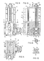
- a rod 11 ( Figure 7) is coaxially mounted within and extends throughout main tube 7.
- Rod 11 can be manually rotated to radially expand or contract a clamp 12.
- a sleeve 61 is concentrically mounted between rod 11 and the inner wall of tube 7.
- Clamp 12 is removably attached to sleeve 61 which can be made to move in an axial direction relative to stationary tube 7.
- Clamp 12 is detachably secured to flange 12b of sleeve 61.
- Clamp 12 can be securely attached to a work member 25.
- socket 49 is manually moved until its cutter 50 is disposed at the desired position relative to work member 25.
- Cutter 50 is then made to rotate in a spiral path across the face 2& of work member 25.
- Valve 25' has a face 26 which it is desired to cut in a plane P-P that is parallel to face 33.
- Clamp 12 is coupled to rod 11.
- One end of rod 11 carries a crank 62.
- the opposite end of rod 11 has oppositely-threaded, spaced portions 17, 17'.
- Discs 13, 14 are threadedly mounted on portions 17, 17', respectively.
- a bushing 16 is disposed between discs 13 and 14.
- a disc 15 is mounted on bushing 16.
- Discs 13, 14 and 15 have longitudinal slots 13', 14', 15', respectively.
- a blade 19 is disposed within each set of aligned slots 13', 14', 15'. Blade 19 has tapered inner walls 20 and a pair of outer gripping jaws 21.
- a shield sleeve 12a ( Figure 7) is slidably mounted on a seal 12a' which is supported by the outer end 7b of tube 7.
- Sleeve 12a protects the bore of tube 7 from collecting metal cuttings.
- Disc 14 is detachably secured to sleeve 61 and to flange 12b.
- Sleeve 61 is disposed .inside tube 7 for axial movement but not rotation relative to rod 11.
- the inner end of sleeve 61 has an external thread 61a and a shoulder 61d.
- a control sleeve 64 has an internal thread 64a which engages thread 61a.
- Control sleeve 64 has an annular groove 64b in which rides a pin 78a which extends through collar 78. Pin 78a prevents the axial movement of sleeve 64 when it is rotated by handle bars 63.
- the maximum.axial displacement of sleeve 61 to the left is limited by a pin 61c riding in a longitudinal slot 61b.
- pin 61c abuts against shoulder 61d.
- the axial displacement of sleeve 61 to the right is limited by wall 64d of sleeve 64.
- Box 40 ( Figures 9-13) has a frame 44 which is provided with a pair of hubs 41a, 41'a that are rotatably supported on brackets 43, 43a, respectively.
- Bolts 43' ( Figure 1) secure brackets 43, 43a to platform 31.
- Shaft 41 extends through and is rotatably mounted in hubs 41a and 41'a.
- Bracket 43a ( Figures 5, 6) has an arcuate slot 41c in which rides an adjusting bolt 41b that can securely fasten box 40 to bracket 43a.
- the transmission 45 ( Figure 10) translates the rotation of shaft 41 into linear travel by socket 49.
- Bevel gear 73 ( Figure 1) on shaft 71 rotates bevel gear 42 on shaft 41.
- Inside frame 44 is a block 45a in which is mounted a worm gear 84 carried by shaft 41.
- Gear 84 meshes with a rotatably mounted pinion gear 85.
- To the lower end of gear 85 is mounted the annular clutch plate 53 having radial recesses 53a therein.
- a transverse pin 46a is carried by screw 46. Pin 46a can selectively engage the recesses 53a in clutch plate 53.
- the portion of lead screw 46 which extends through the top of frame 44 carries a coil spring 52a and a wheel 52. By compressing spring 52a with wheel 52, the lower end of lead screw 46 will move downwardly; pin 46a will disengage from clutch plate 53; and lead screw 46 will disengage from pinion gear 85.
- socket 49 and cutter 50 stop traveling on lead screw 46.
- pin 46a When pin 46a is disengaged from clutch 53 by the exertion of a downward force on wheel 52, lead screw 46 can be hand rotated to allow socket 49 to bring tool 50 to its desired start position opposite to work member 25. If desired, box 40 is first pivoted on brackets 43, 43a relative to platform 31.
- a nut 47 is threadedly coupled to lead screw 46.
- a slide block 48 ( Figure 11) is secured to nut 47 by screws 47a.
- a dovetail slide 51 is formed within the end portions of a pair of opposite sidewalls of frame 44. Block 48 slides in the dovetail 51 and has on its front face a recess 48a for detachably receiving socket 49.
- Socket 49 is adapted to carry conventional cutters 50 which are selected dependent upon the desired cutting operation to be performed on work member 25.
- motor 8 ( Figures 1, 4) is shown as being electrically operated, it can be fluid operated.
- Shaft 57 of motor 8 carries a pulley 58 whose rotation is transmitted by a belt 59 to pulley 60 which rotates . platform 31.
- a pulley 81 is mounted for rotation about tube 7.
- Pulleys 72 and 81 are coupled by a belt 82.
- Pulley 81 is mounted on a sleeve bearing 82' ( Figure 7) between a pair of spaced bearing plates 82a.
- Pulley'81 can be locked to tube 7 through the clutch mechanism 76.
- Clutch 76 includes a rotatable wedge ring 77 and an adjacent wedge ring 79. Rings 77, 79 are mounted on tube 7 and have opposite wedge faces 77'.
- a pin 79a prevents ring 79 from rotating relative to tube 7.
- Pin 79a projects into a recess 7a which limits the axial displacement of ring 79.
- Ring 77 is sandwiched.between ring 79 and the end wall of collar 78. Ring 77 can be -rotated with a handle 80. The rotation-of.ring 77 exerts an axial force to the left (as viewed in Figure 7) against the sloping face 77' of ring 79, thereby locking pulley 81 to stationary tube 7. Thus, when clutch mechanism 76 is engaged, pulley 81 is locked to stationary tube 7.
- tool 10 is clamped to work member 25 with the aid of clamp 12.
- Rotation of crank 62 will rotate rod 11 and move threaded discs 13 and 14 towards each other, thereby expanding clamp 12 and causing jaws 21 to firmly grip work member 25.
- Sleeve 64 is then rotated to cause sleeve 61 to move axially to the right (as viewed in Figure 1), thereby moving work member 25 toward face 33 in the direction of arrow A ( Figure 1).
- Box 40 is pivotably adjusted to the desired angular inclination relative to face 33. For most cutting operations, box 40 will be parallel with face 33. However, to make a bevel cut (Figure 19), box 40 will be inclined relative to face 33.
- Wheel 52 ( Figure 10) is then depressed to disengage clutch 53 from lead screw 46 and from pinion gear 85. While wheel 52 is pressed downwardly, it is also rotated to cause cutter 50 to travel to its start position on face 26 of work member 25. After these preliminary adjustments, tool 10 is ready to become energized by motor 8.
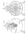
- cutter 50 starts at point 90, and in Figure 18 the starting position of cutter 50 is indicated by the broken line l.
- Cutter 50 will cut a spiral groove G across face 26 of work member 25. Groove G starts at point 90 and ends at point 91.
- Broken lines 2, 3, 4 and 5 indicate the starting points of each successive revolution on spiral groove G. Each such revolution is spaced from its adjacent revolution by a radial distance D ( Figure 17).
- Tool 10 lends itself for use in the field as illustrated in connection with a pipe 25b which is buried in a trench ( Figures 19-20).
- Machine 10 can be lowered into the trench on a winch cable 9c for movement in an axial direction A' so that its clamp 12 fits inside the bore of the buried pipe.
- Cutter 50 is adapted to cut a bevel B on the pipe's flange 26a which has a face F.
- Other cutting operations possible with portable tool 10 will become readily apparent to those skilled in the machining art.
- platform 31 rotates cutter 50 around work member 25, while socket 49 causes the cutter to travel towards the center of platform 31 when both clutches 33 and 76 are engaged.
Landscapes
- Engineering & Computer Science (AREA)
- Mechanical Engineering (AREA)
- Turning (AREA)
- Drilling And Boring (AREA)
Applications Claiming Priority (2)
| Application Number | Priority Date | Filing Date | Title |
|---|---|---|---|
| US06/118,336 US4343207A (en) | 1980-02-04 | 1980-02-04 | Tool for spiral machining |
| US118336 | 1980-02-04 |
Publications (2)
| Publication Number | Publication Date |
|---|---|
| EP0033588A2 true EP0033588A2 (fr) | 1981-08-12 |
| EP0033588A3 EP0033588A3 (fr) | 1983-07-06 |
Family
ID=22377942
Family Applications (1)
| Application Number | Title | Priority Date | Filing Date |
|---|---|---|---|
| EP81300133A Withdrawn EP0033588A3 (fr) | 1980-02-04 | 1981-01-13 | Outil pour usiner des surfaces en forme de spirale |
Country Status (3)
| Country | Link |
|---|---|
| US (1) | US4343207A (fr) |
| EP (1) | EP0033588A3 (fr) |
| JP (1) | JPS56119303A (fr) |
Cited By (6)
| Publication number | Priority date | Publication date | Assignee | Title |
|---|---|---|---|---|
| GB2140729A (en) * | 1983-05-04 | 1984-12-05 | Tube Runner | Portable flange facing and turning machine |
| EP0178103A2 (fr) * | 1984-10-11 | 1986-04-16 | Tube Runner Limited | Dispositif pour profiler des tubes |
| EP0254021A2 (fr) * | 1986-07-24 | 1988-01-27 | Georg Fischer Aktiengesellschaft | Dispositif d'usinage des extrémités de pièces tubulaires |
| WO1998006526A1 (fr) * | 1996-08-12 | 1998-02-19 | Georg Fischer Rohrverbindungstechnik Gmbh | Appareil pour l'usinage des extremites de tubes |
| US6176163B1 (en) | 1998-04-14 | 2001-01-23 | Georg Fischer Rohrverbindungstechnik Gmbh | Pipe end machining unit |
| DE102009040840A1 (de) | 2009-09-09 | 2011-03-10 | Illinois Tool Works Inc., Glenview | Rohrbearbeitungsvorrichtung mit einer Schneideinrichtung |
Families Citing this family (13)
| Publication number | Priority date | Publication date | Assignee | Title |
|---|---|---|---|---|
| FR2517575A1 (fr) * | 1981-12-07 | 1983-06-10 | Skf Cie Applic Mecanique | Machine pour usiner une saignee autour d'un embout de tubulure, notamment lors de l'implantation de cet embout sur une cuve de reacteur nucleaire |
| US4422356A (en) * | 1982-06-15 | 1983-12-27 | Tri Tool Inc. | Cutting tool bit holder |
| US4690592A (en) * | 1983-09-21 | 1987-09-01 | Westinghouse Electric Corp. | Stabilizing attachment for boring head |
| US4543861A (en) * | 1984-05-11 | 1985-10-01 | The E. H. Wachs Company | Portable lathe |
| US4625601A (en) * | 1984-08-15 | 1986-12-02 | Pilot Manufacturing Company | Pipe lathe |
| US4854200A (en) * | 1986-07-02 | 1989-08-08 | Mynhier Charles R | Portable facing and threading machine having an interchangeable taper means |
| US4753143A (en) * | 1986-07-02 | 1988-06-28 | Mynhier Charles R | Portable facing and threading machine |
| US4876931A (en) * | 1988-07-11 | 1989-10-31 | Millo Bertini | Device for machining a sealing groove on an engine block |
| US4981055A (en) * | 1989-03-30 | 1991-01-01 | Tri Tool Inc. | Portable facing tool |
| DE19926829A1 (de) * | 1999-06-12 | 2000-12-14 | Wohlhaupter Gmbh | Vorrichtung zur Bearbeitung von Rohrenden zur Herstellung einer Schweißfuge |
| ITTO20001041A1 (it) * | 2000-11-07 | 2002-05-07 | Goriziane Spa | Macchina cianfrinatrice a teste gemellate per lavorazioni di alta precisione su testate di tubi di grande e medio diametro, particolarmente |
| US7938817B2 (en) * | 2004-09-09 | 2011-05-10 | Plc Medical Systems, Inc. | Patient hydration system and method |
| CN117754010B (zh) * | 2024-02-21 | 2024-06-04 | 江苏久保联实业有限公司 | 一种炉管用镗削直径可变的镗刀装置 |
Citations (3)
| Publication number | Priority date | Publication date | Assignee | Title |
|---|---|---|---|---|
| US2926548A (en) * | 1952-04-11 | 1960-03-01 | D Andrea Marino | Device to impart radial displacements to eccentrically rotating parts |
| US3141365A (en) * | 1961-03-09 | 1964-07-21 | James B Peters | Portable lathe |
| US3772944A (en) * | 1972-01-03 | 1973-11-20 | Dnd Corp | Flange facing machine |
Family Cites Families (8)
| Publication number | Priority date | Publication date | Assignee | Title |
|---|---|---|---|---|
| DE132931C (fr) * | ||||
| US2554207A (en) * | 1942-03-02 | 1951-05-22 | Pegard Marcel | Machine tool |
| US2831386A (en) * | 1952-11-07 | 1958-04-22 | Giddings & Lewis | Continuous feed facing attachment for machine tools |
| US3115055A (en) * | 1961-01-31 | 1963-12-24 | Ismael E Sepulveda | Portable machining tool |
| US3181398A (en) * | 1962-10-29 | 1965-05-04 | John M Rogers | Pipe joint refacing apparatus |
| US3222960A (en) * | 1963-11-19 | 1965-12-14 | John B Gill | Arbor construction for pipe tools |
| GB1526786A (en) * | 1975-09-01 | 1978-09-27 | Gen Electric | Facing machining device |
| US4186630A (en) * | 1978-04-04 | 1980-02-05 | Boise Cascade Corporation | Facing and journal turning machine |
-
1980
- 1980-02-04 US US06/118,336 patent/US4343207A/en not_active Expired - Lifetime
-
1981
- 1981-01-13 EP EP81300133A patent/EP0033588A3/fr not_active Withdrawn
- 1981-02-04 JP JP1447581A patent/JPS56119303A/ja active Pending
Patent Citations (3)
| Publication number | Priority date | Publication date | Assignee | Title |
|---|---|---|---|---|
| US2926548A (en) * | 1952-04-11 | 1960-03-01 | D Andrea Marino | Device to impart radial displacements to eccentrically rotating parts |
| US3141365A (en) * | 1961-03-09 | 1964-07-21 | James B Peters | Portable lathe |
| US3772944A (en) * | 1972-01-03 | 1973-11-20 | Dnd Corp | Flange facing machine |
Cited By (9)
| Publication number | Priority date | Publication date | Assignee | Title |
|---|---|---|---|---|
| GB2140729A (en) * | 1983-05-04 | 1984-12-05 | Tube Runner | Portable flange facing and turning machine |
| EP0178103A2 (fr) * | 1984-10-11 | 1986-04-16 | Tube Runner Limited | Dispositif pour profiler des tubes |
| EP0178103A3 (fr) * | 1984-10-11 | 1986-12-30 | Tube Runner Limited | Dispositif pour profiler des tubes |
| EP0254021A2 (fr) * | 1986-07-24 | 1988-01-27 | Georg Fischer Aktiengesellschaft | Dispositif d'usinage des extrémités de pièces tubulaires |
| EP0254021A3 (fr) * | 1986-07-24 | 1989-11-15 | Georg Fischer Aktiengesellschaft | Dispositif d'usinage des extrémités de pièces tubulaires |
| WO1998006526A1 (fr) * | 1996-08-12 | 1998-02-19 | Georg Fischer Rohrverbindungstechnik Gmbh | Appareil pour l'usinage des extremites de tubes |
| US6176163B1 (en) | 1998-04-14 | 2001-01-23 | Georg Fischer Rohrverbindungstechnik Gmbh | Pipe end machining unit |
| DE102009040840A1 (de) | 2009-09-09 | 2011-03-10 | Illinois Tool Works Inc., Glenview | Rohrbearbeitungsvorrichtung mit einer Schneideinrichtung |
| WO2011031754A1 (fr) | 2009-09-09 | 2011-03-17 | Illinois Tool Works Inc. | Appareil d'usinage de tuyaux avec un dispositif de coupe |
Also Published As
| Publication number | Publication date |
|---|---|
| JPS56119303A (en) | 1981-09-18 |
| EP0033588A3 (fr) | 1983-07-06 |
| US4343207A (en) | 1982-08-10 |
Similar Documents
| Publication | Publication Date | Title |
|---|---|---|
| EP0033588A2 (fr) | Outil pour usiner des surfaces en forme de spirale | |
| US3942248A (en) | Pipe cutting device | |
| CN206356650U (zh) | 管道切割机 | |
| US3651569A (en) | Device for working a cylindrical work-piece | |
| US3733939A (en) | Apparatus for forming precision surfaces on ends of large pipes and like work places | |
| US7578643B1 (en) | Simultaneous pipe cutting and chamfering device | |
| US7811034B1 (en) | Simultaneous pipe cutting, chamfering and grooving device | |
| CN206326182U (zh) | 高效管道切割机 | |
| US4509236A (en) | Boring machines | |
| CA2647050A1 (fr) | Tour conique | |
| SE411107B (sv) | Sett och slipmaskin for bearbetning av flersidiga arbetsstycken, varvid yttre mantelytor av flersidiga kroppar kan bearbetas | |
| CN107737991A (zh) | 一种型钢生产切割机 | |
| US4854200A (en) | Portable facing and threading machine having an interchangeable taper means | |
| EP0100355A1 (fr) | Machine-outil portative pour la preparation au soudage de joints de conduite | |
| US5769575A (en) | Oscillatory motion device for drill press | |
| US4470734A (en) | Portable tube end preparation tool | |
| JP2021534011A (ja) | 溶接切削機および溶接部の切削方法 | |
| CN211464944U (zh) | 一种双工位全自动接管加工装置 | |
| CN1198695A (zh) | 管端加工设备 | |
| US3617143A (en) | Arcuate hole-cutting tool | |
| CN220073954U (zh) | 一种汽车刹车片打孔装置 | |
| US4365528A (en) | Portable lathe | |
| US4116095A (en) | Metal sawing or milling machine | |
| JPH0540881Y2 (fr) | ||
| US4061078A (en) | Device for removing external circular fins from pipe joints |
Legal Events
| Date | Code | Title | Description |
|---|---|---|---|
| PUAI | Public reference made under article 153(3) epc to a published international application that has entered the european phase |
Free format text: ORIGINAL CODE: 0009012 |
|
| AK | Designated contracting states |
Designated state(s): BE DE FR GB IT NL |
|
| 17P | Request for examination filed |
Effective date: 19811216 |
|
| PUAL | Search report despatched |
Free format text: ORIGINAL CODE: 0009013 |
|
| AK | Designated contracting states |
Designated state(s): BE DE FR GB IT NL |
|
| STAA | Information on the status of an ep patent application or granted ep patent |
Free format text: STATUS: THE APPLICATION IS DEEMED TO BE WITHDRAWN |
|
| 18D | Application deemed to be withdrawn |
Effective date: 19840402 |
|
| RIN1 | Information on inventor provided before grant (corrected) |
Inventor name: PAYSINGER, JOSEPH R. |