EP0032333B1 - Dispositif de détection de défauts de combustion dans un moteur à explosions - Google Patents
Dispositif de détection de défauts de combustion dans un moteur à explosions Download PDFInfo
- Publication number
- EP0032333B1 EP0032333B1 EP80401793A EP80401793A EP0032333B1 EP 0032333 B1 EP0032333 B1 EP 0032333B1 EP 80401793 A EP80401793 A EP 80401793A EP 80401793 A EP80401793 A EP 80401793A EP 0032333 B1 EP0032333 B1 EP 0032333B1
- Authority
- EP
- European Patent Office
- Prior art keywords
- engine
- output
- cylinder
- cycle
- detector
- Prior art date
- Legal status (The legal status is an assumption and is not a legal conclusion. Google has not performed a legal analysis and makes no representation as to the accuracy of the status listed.)
- Expired
Links
Images
Classifications
-
- F—MECHANICAL ENGINEERING; LIGHTING; HEATING; WEAPONS; BLASTING
- F02—COMBUSTION ENGINES; HOT-GAS OR COMBUSTION-PRODUCT ENGINE PLANTS
- F02P—IGNITION, OTHER THAN COMPRESSION IGNITION, FOR INTERNAL-COMBUSTION ENGINES; TESTING OF IGNITION TIMING IN COMPRESSION-IGNITION ENGINES
- F02P5/00—Advancing or retarding ignition; Control therefor
- F02P5/04—Advancing or retarding ignition; Control therefor automatically, as a function of the working conditions of the engine or vehicle or of the atmospheric conditions
- F02P5/145—Advancing or retarding ignition; Control therefor automatically, as a function of the working conditions of the engine or vehicle or of the atmospheric conditions using electrical means
- F02P5/15—Digital data processing
- F02P5/152—Digital data processing dependent on pinking
- F02P5/1522—Digital data processing dependent on pinking with particular means concerning an individual cylinder
-
- F—MECHANICAL ENGINEERING; LIGHTING; HEATING; WEAPONS; BLASTING
- F02—COMBUSTION ENGINES; HOT-GAS OR COMBUSTION-PRODUCT ENGINE PLANTS
- F02P—IGNITION, OTHER THAN COMPRESSION IGNITION, FOR INTERNAL-COMBUSTION ENGINES; TESTING OF IGNITION TIMING IN COMPRESSION-IGNITION ENGINES
- F02P5/00—Advancing or retarding ignition; Control therefor
- F02P5/04—Advancing or retarding ignition; Control therefor automatically, as a function of the working conditions of the engine or vehicle or of the atmospheric conditions
- F02P5/145—Advancing or retarding ignition; Control therefor automatically, as a function of the working conditions of the engine or vehicle or of the atmospheric conditions using electrical means
- F02P5/15—Digital data processing
- F02P5/152—Digital data processing dependent on pinking
- F02P5/1523—Digital data processing dependent on pinking with particular laws of return to advance, e.g. step by step, differing from the laws of retard
-
- G—PHYSICS
- G01—MEASURING; TESTING
- G01L—MEASURING FORCE, STRESS, TORQUE, WORK, MECHANICAL POWER, MECHANICAL EFFICIENCY, OR FLUID PRESSURE
- G01L23/00—Devices or apparatus for measuring or indicating or recording rapid changes, such as oscillations, in the pressure of steam, gas, or liquid; Indicators for determining work or energy of steam, internal-combustion, or other fluid-pressure engines from the condition of the working fluid
- G01L23/22—Devices or apparatus for measuring or indicating or recording rapid changes, such as oscillations, in the pressure of steam, gas, or liquid; Indicators for determining work or energy of steam, internal-combustion, or other fluid-pressure engines from the condition of the working fluid for detecting or indicating knocks in internal-combustion engines; Units comprising pressure-sensitive members combined with ignitors for firing internal-combustion engines
- G01L23/221—Devices or apparatus for measuring or indicating or recording rapid changes, such as oscillations, in the pressure of steam, gas, or liquid; Indicators for determining work or energy of steam, internal-combustion, or other fluid-pressure engines from the condition of the working fluid for detecting or indicating knocks in internal-combustion engines; Units comprising pressure-sensitive members combined with ignitors for firing internal-combustion engines for detecting or indicating knocks in internal combustion engines
- G01L23/225—Devices or apparatus for measuring or indicating or recording rapid changes, such as oscillations, in the pressure of steam, gas, or liquid; Indicators for determining work or energy of steam, internal-combustion, or other fluid-pressure engines from the condition of the working fluid for detecting or indicating knocks in internal-combustion engines; Units comprising pressure-sensitive members combined with ignitors for firing internal-combustion engines for detecting or indicating knocks in internal combustion engines circuit arrangements therefor
-
- Y—GENERAL TAGGING OF NEW TECHNOLOGICAL DEVELOPMENTS; GENERAL TAGGING OF CROSS-SECTIONAL TECHNOLOGIES SPANNING OVER SEVERAL SECTIONS OF THE IPC; TECHNICAL SUBJECTS COVERED BY FORMER USPC CROSS-REFERENCE ART COLLECTIONS [XRACs] AND DIGESTS
- Y02—TECHNOLOGIES OR APPLICATIONS FOR MITIGATION OR ADAPTATION AGAINST CLIMATE CHANGE
- Y02T—CLIMATE CHANGE MITIGATION TECHNOLOGIES RELATED TO TRANSPORTATION
- Y02T10/00—Road transport of goods or passengers
- Y02T10/10—Internal combustion engine [ICE] based vehicles
- Y02T10/40—Engine management systems
Definitions
- the present invention relates to the detection of combustion faults in an explosion engine and it relates, more particularly, to the fault known under the name of "knocking".
- Detection of knocking in an engine with one or more cylinders is generally done using an accelerometer-type sensor or a pressure sensor, suitably placed on the cylinder head of the engine.
- the sensor transmits a certain amount of information to a system responsible for processing the signal.
- This information mainly represents the "noise" due to the operation of the engine, noise from which it is necessary to extract the possible information of the existence of clicking.
- An analog detection device is also known according to document DE-A-2 925 770 comprising a sensor placed on the cylinder head of the engine and a system for processing the signals supplied by this sensor, comprising means for temporary storage, during of each cycle, the data collected and relating to each cylinder, as well as means of comparison of this data with that which is collected during the following cycle.
- this system being entirely analog is unreliable and lends itself poorly to an application in the automotive field, where such devices must operate in a relatively difficult environment.
- the invention therefore aims to provide a simple and reliable device capable of delivering reliable information as soon as the knocking appears.
- a device for detecting combustion faults in an explosion engine comprising a sensor placed on the cylinder head of the engine and a system for processing the signals from said sensor, comprising means for temporary storage during each cycle. , data relating to each cylinder of the engine and means for comparing the data relating to each cylinder stored successively during a cycle with the corresponding data obtained during the following cycle, characterized in that the operating system comprises means for converting the analog data supplied by the sensor, into digital data and in that said temporary storage means consist of as many shift registers connected in series as the engine comprises cylinders, said registers being connected to a switching circuit controlled by the output signal of said comparison means and intended to connect the first shift register, so it with the output of the converter, ie with the output of the last shift register in the event of a combustion fault, this latter output being further connected to summation means with a threshold value (A), connected to said comparison means.
- A threshold value
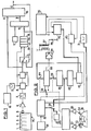
- the device described is supposed to be used for the detection of knocking on an explosion engine M with four cylinders 1, 2, 3, 4.
- This device consists of an analog part and a digital part.
- the analog part includes a knock sensor 5, for example an accelerometer, fixed on the motor M, a charge amplifier 6, a bandpass filter 7, intended to eliminate unwanted frequencies, and a circuit 8 which develops a voltage of maximum peak during each measurement period corresponding to a slot obtained by a decoder 9.
- This decoder can be triggered for example from an electronic ignition system 10.
- the slot makes it possible to measure, for each cylinder, in an angular interval during which the rattling is likely to occur.
- the digital part includes an analog / digital converter 11, a switching circuit 12, a set of four shift registers 13, 14, 15, 16 connected in series, an encoder 17, a summator 18 and a comparator 19 with two inputs A, B and an output C.
- the analog part of the circuit develops a voltage as a function of the maximum peak value given by the knock sensor 5, during the duration of the slot.
- the analog / digital converter transforms this voltage into a digital value which is sent, on the one hand to the switch 12 and on the other hand to the input A of the comparator 19.
- the shift registers 13, 14, 15, 16 contain the maximum peak values corresponding respectively to the cylinders 2, 4 , 3, 1. These values are those which were noted, for each cylinder, in the previous cycle.
- the comparator output C is at level "1" and is used to decrease the ignition advance, so as to eliminate the rattling. In this case, the output of the register 16 is looped back to the register 13, by the switch 12, before making the shift.
- the shift of the registers 13, 14, 15, 16 is triggered by the end of the slot obtained by the decoder 9.
- This threshold is developed by measuring, at each engine cycle, the noise level during an angular course of observation of the phenomenon, this noise level being stored for comparison with that of the following cycle. This makes the system independent of the dispersions of the noise level from one engine to another and of its variation as a function of the load, the speed and the evolution of the engine over time.
- the previous circuit identified by the general reference 20, is associated with the ignition triggering device shown in FIG. 2 of French patent application No. 7817157.
- This device comprises two sensors 24 and 25 placed in the vicinity of a disc 26 provided with a notch 27.
- the sensor 25 and the mark 27 are positioned so that the passage of the mark in front of the sensor takes place for an angular position of the corresponding crankshaft at minimum ignition advance.
- the sensor 24 is positioned in advance by a degree on the sensor 25, the value of the angle ⁇ being such that a is greater than the maximum amplitude desired in advance relative to the initial advance.
- the outputs of sensors 24 and 25 are connected via shaping circuits 26 and 27 to the inputs of a rocker circuit 28, a first output of which controls a switch 29.
- the latter is intended to connect a programmable divider down-counter 30 receiving pulses from a clock 31, either to a circuit 32 for memorizing the angle (3 equal to the difference between 360 ° and the angle a separating the two sensors 24 and 25, or to a locking circuit 33.
- the other output of the rocker 28 controls a second switch 34 intended to connect the programmable down-counter divider 30 to a first or to a second input of a prepositive up-down counter 35 whose output is connected to a power stage.
- 36 supplying the ignition coil 37 with spark plugs such as 38 from the engine M in FIG. 1.
- the up-down counter 35 has an output connected to the locking circuit 33 via a contact 39 coupled to the switch 34.
- the output of the locking circuit 33 is connected to a memory 40 and to the programmable down-counting divider 30 by the intermediate of the switch 29.
- the output of the memory 40 is itself connected to a binary adder 41 of which another input is connected to the circuit 20, via a circuit 42 of additive corrections.
- the output of the binary adder 41 is connected to a prepositioning input of the up-down counter 35, by means of another contact 44 coupled to the switch 34.
- the switches 29, 34 and the contacts 39, 44 can be controlled indifferently by one or the other of the outputs of the rocker 28.
- the decoder 9 (FIG. 1) giving the slot during which the measurement is carried out, receives information representative of the state of the programmable down-counter divider 30.
- circuit 20 which is output C of comparator 19 is connected to circuit 42 of additive corrections, consisting of an up-down counter.
- the latter is also connected to the output of the up-down programmable divider 30, through a divider 45, one input of which is connected to the output C of the comparator 19.
- the up-down counter 42 acts in the counting direction, which causes a decrease in the advance. This decrease increases with each cycle, as long as the rattling remains, up to a predetermined maximum.
- the up-down counter 42 acts in the down-counting direction which causes the progressive return to the initial advance. This return to the initial advance takes place more slowly than the reduction in advance under the effect of clicking, by action on the divider 45 from the output C of the comparator 19.
Landscapes
- Engineering & Computer Science (AREA)
- Chemical & Material Sciences (AREA)
- Combustion & Propulsion (AREA)
- Signal Processing (AREA)
- Mechanical Engineering (AREA)
- General Engineering & Computer Science (AREA)
- Physics & Mathematics (AREA)
- General Physics & Mathematics (AREA)
- Combined Controls Of Internal Combustion Engines (AREA)
- Testing Of Engines (AREA)
Applications Claiming Priority (2)
| Application Number | Priority Date | Filing Date | Title |
|---|---|---|---|
| FR8000191 | 1980-01-07 | ||
| FR8000191A FR2473114A1 (fr) | 1980-01-07 | 1980-01-07 | Dispositif de detection de defauts de combustion dans un moteur a explosions |
Publications (2)
| Publication Number | Publication Date |
|---|---|
| EP0032333A1 EP0032333A1 (fr) | 1981-07-22 |
| EP0032333B1 true EP0032333B1 (fr) | 1984-05-30 |
Family
ID=9237257
Family Applications (1)
| Application Number | Title | Priority Date | Filing Date |
|---|---|---|---|
| EP80401793A Expired EP0032333B1 (fr) | 1980-01-07 | 1980-12-12 | Dispositif de détection de défauts de combustion dans un moteur à explosions |
Country Status (4)
| Country | Link |
|---|---|
| US (1) | US4355534A (el) |
| EP (1) | EP0032333B1 (el) |
| DE (1) | DE3068076D1 (el) |
| FR (1) | FR2473114A1 (el) |
Families Citing this family (11)
| Publication number | Priority date | Publication date | Assignee | Title |
|---|---|---|---|---|
| DE3121120A1 (de) * | 1981-04-15 | 1982-11-04 | Robert Bosch Gmbh, 7000 Stuttgart | Verfahren und vorrichtung zum erkennen irregulaerer verbrennunsvorgaenge in einer brennkraftmaschine |
| DE3137016C2 (de) * | 1981-09-17 | 1985-01-03 | Robert Bosch Gmbh, 7000 Stuttgart | Vorrichtung zur Erkennung des Klopfens einer Brennkraftmaschine |
| JPS5857074A (ja) * | 1981-09-30 | 1983-04-05 | Nippon Denso Co Ltd | 内燃機関の点火時期制御装置 |
| JPS5946519A (ja) * | 1982-04-08 | 1984-03-15 | Nippon Denso Co Ltd | 内燃機関用ノツキング検出装置 |
| JPS597777A (ja) * | 1982-07-05 | 1984-01-14 | Hitachi Ltd | ノツク制御装置 |
| EP0102779A3 (en) * | 1982-08-12 | 1985-05-08 | Bl Technology Limited | Method and apparatus for detecting knock in a spark ignition engine |
| US4675821A (en) * | 1983-02-18 | 1987-06-23 | Toyota Jidosha Kabushiki Kaisha | Method and apparatus for detecting knocking |
| JPS59185874A (ja) * | 1983-04-08 | 1984-10-22 | Hitachi Ltd | 内燃機関の点火装置 |
| DE3427190A1 (de) * | 1984-07-24 | 1986-02-06 | Atlas Fahrzeugtechnik GmbH, 5980 Werdohl | Klopfintensitaetsmessgeraet |
| IT1237595B (it) * | 1989-10-03 | 1993-06-08 | Marelli Autronica | Dispositivo per la rilevazione, cilindro per cilindro, della detonazione in un motore a combustione interna a ciclo otto a piu' cilindri |
| CN116044567B (zh) * | 2023-01-02 | 2024-03-22 | 重庆长安汽车股份有限公司 | 一种发动机爆震检测方法 |
Citations (4)
| Publication number | Priority date | Publication date | Assignee | Title |
|---|---|---|---|---|
| US4002155A (en) * | 1976-01-12 | 1977-01-11 | General Motors Corporation | Engine and engine spark timing control with knock limiting etc. |
| DE2625971A1 (de) * | 1976-06-10 | 1977-12-29 | Bosch Gmbh Robert | Verfahren und einrichtung zur erkennung von stoerungen bei einzelnen zylindern von brennkraftmaschinen |
| DE2916591A1 (de) * | 1978-04-24 | 1979-10-25 | Nippon Soken | Verfahren und vorrichtung zur feststellung des klopfens von brennkraftmaschinen |
| DE2925770A1 (de) * | 1978-06-27 | 1980-01-03 | Nissan Motor | Steuervorrichtung fuer den zuendzeitpunkt einer brennkraftmaschine |
Family Cites Families (1)
| Publication number | Priority date | Publication date | Assignee | Title |
|---|---|---|---|---|
| DE2605335A1 (de) * | 1976-02-11 | 1977-08-18 | Krupp Gmbh | Verfahren zur messung der klopfstaerke von verbrennungsmotoren |
-
1980
- 1980-01-07 FR FR8000191A patent/FR2473114A1/fr active Granted
- 1980-12-12 EP EP80401793A patent/EP0032333B1/fr not_active Expired
- 1980-12-12 DE DE8080401793T patent/DE3068076D1/de not_active Expired
- 1980-12-31 US US06/221,570 patent/US4355534A/en not_active Expired - Fee Related
Patent Citations (4)
| Publication number | Priority date | Publication date | Assignee | Title |
|---|---|---|---|---|
| US4002155A (en) * | 1976-01-12 | 1977-01-11 | General Motors Corporation | Engine and engine spark timing control with knock limiting etc. |
| DE2625971A1 (de) * | 1976-06-10 | 1977-12-29 | Bosch Gmbh Robert | Verfahren und einrichtung zur erkennung von stoerungen bei einzelnen zylindern von brennkraftmaschinen |
| DE2916591A1 (de) * | 1978-04-24 | 1979-10-25 | Nippon Soken | Verfahren und vorrichtung zur feststellung des klopfens von brennkraftmaschinen |
| DE2925770A1 (de) * | 1978-06-27 | 1980-01-03 | Nissan Motor | Steuervorrichtung fuer den zuendzeitpunkt einer brennkraftmaschine |
Also Published As
| Publication number | Publication date |
|---|---|
| FR2473114A1 (fr) | 1981-07-10 |
| EP0032333A1 (fr) | 1981-07-22 |
| DE3068076D1 (en) | 1984-07-05 |
| FR2473114B1 (el) | 1982-10-29 |
| US4355534A (en) | 1982-10-26 |
Similar Documents
| Publication | Publication Date | Title |
|---|---|---|
| CA1139829A (fr) | Methode et dispositif de reglage automatique de l'allumage d'un moteur a allumage commande | |
| CA1098957A (fr) | Dispositif de reglage optimal de l'allumage d'un moteur a allumage commande en cours de fonctionnement | |
| EP0032333B1 (fr) | Dispositif de détection de défauts de combustion dans un moteur à explosions | |
| FR2468113A1 (fr) | Dispositif pour detecter les vibrations intervenant lors du cognement d'un moteur a combustion interne | |
| EP0013846B1 (fr) | Procédé et dispositif de repérage de la position angulaire d'une pièce animée d'un mouvement de rotation | |
| EP0187081B1 (fr) | Procédé et chaîne de traitement du signal analogique de sortie d'un capteur | |
| EP1548418B9 (fr) | Système de calibrage d'une chaîne d'acquisition de la pression dans un cylindre de moteur Diesel de véhicule automobile | |
| FR2472091A1 (fr) | Dispositif d'allumage evitant le cliquetis au cours du fonctionnement d'un moteur a combustion interne | |
| EP0006367B1 (fr) | Dispositif de déclenchement, notamment de l'allumage d'un moteur à combustion interne | |
| FR2524647A1 (fr) | Dispositif de detection de panne d'un capteur | |
| FR2808589A1 (fr) | Procede de detection de defauts dans l'exploitation de signaux de capteur | |
| FR2459377A1 (fr) | Dispositif de reglage de l'allumage pour un moteur a combustion interne et dispositif pour y detecter un cliquetis s'y produisant | |
| FR2467396A1 (fr) | Detecteur de cliquetis pour un moteur a combustion interne | |
| EP0101342B1 (fr) | Procédé d'optimisation de l'avance à l'allumage pour moteur à combustion interne | |
| FR2797952A1 (fr) | Dispositif de detection de cognement pour un moteur a combustion interne | |
| EP0654604A1 (fr) | Procédé et dispositif d'allumage à bobine avec des décharges additionnelles pour diagnostics | |
| WO2006021417A1 (fr) | Procede pour controler le demarrage d’un moteur | |
| FR2818737A1 (fr) | Procede de detection d'une singularite notamment d'un repere de reference d'un disque phonique associe a l'arbre d'un moteur a combustion interne | |
| EP0029374A1 (fr) | Générateur de signal de correction d'angle d'avance à l'allumage sous l'action de cliquetis | |
| EP0272965B1 (fr) | Convertisseur fréquence-tension | |
| EP0187071B1 (fr) | Système électronique d'élaboration d'un signal synchrone d'un signal d'allumage de moteur à combustion interne | |
| FR2498255A1 (fr) | Dispositif d'ajustement rapide, en periode d'acceleration, de l'avance a l'allumage d'un moteur a allumage commande | |
| EP0736688B1 (fr) | Dispositif de détection de la phase de fonctionnement d'un moteur à allumage simultané par paires de cylindre, notamment pour véhicule automobile | |
| EP0793778B1 (fr) | Procede de retour a l'avance nominale, en l'absence de detection de cliquetis | |
| FR2464482A1 (fr) | Dispositif pour determiner l'instant de reception d'une impulsion acoustique |
Legal Events
| Date | Code | Title | Description |
|---|---|---|---|
| PUAI | Public reference made under article 153(3) epc to a published international application that has entered the european phase |
Free format text: ORIGINAL CODE: 0009012 |
|
| AK | Designated contracting states |
Designated state(s): DE GB IT |
|
| 17P | Request for examination filed |
Effective date: 19810625 |
|
| RAP1 | Party data changed (applicant data changed or rights of an application transferred) |
Owner name: AUTOMOBILES CITROEN Owner name: AUTOMOBILES PEUGEOT |
|
| ITF | It: translation for a ep patent filed |
Owner name: ING. C. GREGORJ S.P.A. |
|
| GRAA | (expected) grant |
Free format text: ORIGINAL CODE: 0009210 |
|
| AK | Designated contracting states |
Designated state(s): DE GB IT |
|
| REF | Corresponds to: |
Ref document number: 3068076 Country of ref document: DE Date of ref document: 19840705 |
|
| PLBE | No opposition filed within time limit |
Free format text: ORIGINAL CODE: 0009261 |
|
| STAA | Information on the status of an ep patent application or granted ep patent |
Free format text: STATUS: NO OPPOSITION FILED WITHIN TIME LIMIT |
|
| 26N | No opposition filed | ||
| ITPR | It: changes in ownership of a european patent |
Owner name: OFFERTA DI LICENZA AL PUBBLICO |
|
| REG | Reference to a national code |
Ref country code: GB Ref legal event code: 746 |
|
| ITTA | It: last paid annual fee | ||
| PGFP | Annual fee paid to national office [announced via postgrant information from national office to epo] |
Ref country code: DE Payment date: 19931122 Year of fee payment: 14 |
|
| PGFP | Annual fee paid to national office [announced via postgrant information from national office to epo] |
Ref country code: GB Payment date: 19931207 Year of fee payment: 14 |
|
| PG25 | Lapsed in a contracting state [announced via postgrant information from national office to epo] |
Ref country code: GB Effective date: 19941212 |
|
| GBPC | Gb: european patent ceased through non-payment of renewal fee |
Effective date: 19941212 |
|
| PG25 | Lapsed in a contracting state [announced via postgrant information from national office to epo] |
Ref country code: DE Effective date: 19950901 |