EP0031211B1 - Motor vehicle lamp reflector - Google Patents
Motor vehicle lamp reflector Download PDFInfo
- Publication number
- EP0031211B1 EP0031211B1 EP80304421A EP80304421A EP0031211B1 EP 0031211 B1 EP0031211 B1 EP 0031211B1 EP 80304421 A EP80304421 A EP 80304421A EP 80304421 A EP80304421 A EP 80304421A EP 0031211 B1 EP0031211 B1 EP 0031211B1
- Authority
- EP
- European Patent Office
- Prior art keywords
- reflective surface
- reflector
- curves
- portions
- lateral
- Prior art date
- Legal status (The legal status is an assumption and is not a legal conclusion. Google has not performed a legal analysis and makes no representation as to the accuracy of the status listed.)
- Expired
Links
- 230000000694 effects Effects 0.000 claims description 2
- 230000008901 benefit Effects 0.000 description 4
- 238000010276 construction Methods 0.000 description 4
- 230000001154 acute effect Effects 0.000 description 2
Images

Classifications
-
- F—MECHANICAL ENGINEERING; LIGHTING; HEATING; WEAPONS; BLASTING
- F21—LIGHTING
- F21S—NON-PORTABLE LIGHTING DEVICES; SYSTEMS THEREOF; VEHICLE LIGHTING DEVICES SPECIALLY ADAPTED FOR VEHICLE EXTERIORS
- F21S41/00—Illuminating devices specially adapted for vehicle exteriors, e.g. headlamps
- F21S41/30—Illuminating devices specially adapted for vehicle exteriors, e.g. headlamps characterised by reflectors
- F21S41/32—Optical layout thereof
- F21S41/33—Multi-surface reflectors, e.g. reflectors with facets or reflectors with portions of different curvature
- F21S41/334—Multi-surface reflectors, e.g. reflectors with facets or reflectors with portions of different curvature the reflector consisting of patch like sectors
- F21S41/335—Multi-surface reflectors, e.g. reflectors with facets or reflectors with portions of different curvature the reflector consisting of patch like sectors with continuity at the junction between adjacent areas
Definitions
- This invention relates to a motor vehicle lamp reflector and relates more particularly to a so-called rectangular reflector, i.e. a reflector having a substantially rectangular front opening rather than a circular front opening.
- rectangular reflectors are becoming increasingly popular.
- the commonly used types of rectangular reflector have a simple paraboloidal reflective surface and it will be appreciated that, because of the requirement to provide a rectangular front opening, the whole of the inner surface of the reflector body cannot have a paraboloidal form if the front opening of the reflector is to be defined by a planar rim. Accordingly, it is commonly the practice to provide upper and lower fill-in portions which are planar.
- planar fill-in portions are also possessed, for example, by the more complex rectangular reflectors disclosed in GB-A-2000266 where the reflective surface is composed of a plurality of paraboloidal or ellipsoidal surfaces having common foci but different focal lengths.
- the disadvantage of a rectangular reflector having planar fill-in portions is that these planar portions can provide surfaces from which stray reflections occur and this provides the lamp designer with problems in obtaining the required light output and distribution pattern.
- reflection off the upper, planar fill-in portion is particularly undesirable because this can lead to further reflection off the lower planar fill-in portion which in turn produces an upward reflection which can dazzle oncoming drivers.
- a shield associated with a bulb filament is provided for preventing reflection off the lower part of the reflector and so automatically shields the lower planar fill-in portion from light rays emanating directly from the filament.
- a bulb shield is relatively small and does not materially reduce the possibility of reflection off the upper fill-in portion onto the lower fill-in portion.
- unwanted direct reflection off the lower fill-in portion can occur because the aforementioned bulb shield is not provided.
- lamp reflectors having front openings of other shapes such as substantially trapezoidal.
- present invention is applicable, of course, to any reflectors which normally require one or more planar or substantially planar fill-in portions and the term "rectangular reflector" as used herein is to be construed accordingly.
- US-A-1559212 discloses an automobile headlight reflector having a front opening which, because of the complex reflector design, is not quite circular.
- the shape of the reflective surface is produced by revolving a conic section about its focal axis and at the same time changing the focal length thereof so that it is at a minimum at the top of the reflector and at a maximum at the bottom of the reflector, the conic section being displaced along the focal axis so that the focus always remains at the same point.
- the problems of planar fill-in portions do not arise, but for aesthetic reasons such reflectors are becoming increasingly unacceptable.
- a rectangular reflector (as defined herein) comprising a dished body having a front opening and an internal reflective surface, said reflective surface having an upper, a lower and a pair of lateral reflective surface portions, wherein at least one of the upper and lower reflective surface portions comprises a multiplicity of non-circular curves extending forwardly of the body to terminate at said front opening, said curves having coincident foci, and said curves increasing in focal length from the centre of the reflective surface to the lateral reflective surface portions.
- the non-circular curves are arranged in side-by side groups.
- the curves in each group may have the same focal length or may have focal lengths which increase progressively in the manner described above, there being discontinuities in the reflective surface between adjacent groups so that there is a stepwise change in the focal lengths of the non-circular curve at each side of each group and an adjacent curve in an adjacent group.
- the upper and lower reflective surface portions are constituted by curves in the manner specified in the last preceding paragraph.
- the curves constituting the upper reflective surface may have foci and focal axes which are coincident with the foci and focal axes of the curves of the lower reflective surface, although it is within the scope of the present invention to arrange for foci not to be coincident and/or for the focal axes not to be coincident.
- the curves may be parabolic or elliptical.
- the present invention is also applicable to rectangular reflectors where the upper half of the reflective surface is stepped relative to the lower half of the reflective surface so that, in effect, there are defined a pair of upper lateral reflective surface portions and a pair of lower lateral reflective surface portions with a step between the upper and lower lateral reflective surface portions at each side of the reflector.
- the present invention is applicable to reflectors in which two pairs of lateral reflective surface portions are provided, with one pair being disposed outwardly of the other pair, and said other pair of reflective portions having a focal length which is less than that of said one pair. Examples of such a type of reflector are disclosed in our above-mentioned GB-A-2 000 266.
- the conventional rectangular reflector comprises a dished body 10 having a generally rectangular front opening 11 defined by a planar rim, and a circular rear opening 12 for receiving a bulb (not shown).
- the body 10 is formed so that, in its internal surface, there is defined a paraboloidal reflector 13. Because of the shape of the front opening 11, the paraboloidal reflective portion extends only to the front opening 11 at the lateral edges of the latter.
- the upper and lower longitudinal edges of the opening 11 are defined by upper and lower, planar fill-in portions 14 and 15, respectively. These fill-in portions 14 and 15 are undesirable for the reasons mentioned hereinbefore.
- the lamp reflector illustrated therein comprises a dished body 20 having a substantially rectangular front opening 21 defined by a planar rim, and a circular rear opening 22.
- the whole of the internal surface of the body 20 save for a portion thereof around the rear opening 22 is rendered reflective.
- the reflective surface consists of a pair of paraboloidal, lateral reflective surface portions 23 and 24 which lie on the surface of the same paraboloid (parabola of revolution).
- the reflective surface within the body 20 also has upper and lower reflective surface portions 25 and 26 which do not form part of the aforesaid paraboloid and extend from adjacent the rear opening 22 to terminate at the front opening 21.
- each of the upper and lower reflective surface portions 25 and 26 is formed from an infinite number of parabolic curves having foci and focal axes which are coincident with the focus and focal axis of the lateral reflective portions 23 and 24.
- the parabolic curves defining the reflector surface portion 25 and 26 increase progressively in the focal length from the centre of the reflective surface to the lateral reflective surface portions 23 and 24.
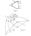
- the construction of the lower reflective surface portion 25 is illustrated and it is to be appreciated that the upper reflective surface portion is similarly constructed.
- Line X-X represents an axis with which the focal axes of all of the curves and of the reflective surface portions 23 and 24 are coincident.
- the point F represents the point at which all of the aforesaid foci are coincident. Only four parabolic curves A-A, B-B, C-C and D-D are illustrated in Fig. 5.
- the curves A-A and C-C represent the lateral limit of the lower reflective surface portion 26, i.e. the lines along which the reflective surface portion 26 merges with the portions 23 and 24, respectively.
- the curve B-B is the curve which lies at the centre of the portion 26, i.e. it lies in a vertical plane in which the axis X-X lies.
- the curve D-D represents a typical curve between curves A-A and B-B. As can be seen from Fig.
- the focal length f b of curve B-B is less than the focal length f d of curve D-D which in turn is less than the focal length F A and F C of curve A-A and C-C.
- the focal length f a and f c are equal and are the same as the focal length of the lateral reflective surface portions 23 and 24. The focal lengths of the curves progressively increase from curve B-B to curve A-A and curve C-C.
- the lamp reflector of Figs. 2-4 has the added advantage that, because of the shape of the upper and lower reflective surface portions 25 and 26, there is a general horizontal spreading of the light reflected by such surface and this is advantageous particularly for road vehicle applications where lensing is normally provided for effecting a horizontal spread of light from regions above and below the filament.
- the lamp reflector of Figs. 2-4 has the advantage that it enables the lensing to be simplified. It will be appreciated that the lamp reflector of Figs. 2-4 will normally be used with a lens element fitted over the front opening 21 so as to modify the beam pattern to satisfy vehicle lighting regulations.
- the lamp reflector of Figs. 2-4 can be used with a standard twin filament shielded bulb to enable a lamp assembly fitted with such a reflector to be used both under passing beam conditions and driving beam conditions.
- the lamp reflector were intended for use in a lamp assembly for use solely under passing beam conditions using a shielded bulb, then the bottom part of the reflector would not be used in any case and it would be necessary to provide a configurated reflective surface such as lower reflective surface portion 26.
- a lamp reflector which, instead of having a single paraboloidal surface such as surface 13 of the lamp reflector of Fig. 1, has a reflective surface in which upper and lower surface portions are divided by a step so that the focal points of the upper and lower reflective portions are separated and the focal length of the lower reflective portion is greater than that of the upper reflective portion.
- the lateral reflective surface portions 23 and 24 have been described as being paraboloidal. However, it is to be appreciated that the lateral surface portions 23 and 24 may be ellipsoidal i.e. shaped to lie on the surface of an ellipse of revolution. Alternatively, the lateral surface portions 23 and 24 may be shaped so as to lie on a surface formed by rotating an ellipse or other non-circular conic section having a focus about an axis which passes through the focus and which is inclined at an acute angle to the focal axis of the conic section.
- each curve may take the form of part of the axial section of a surface formed by rotation of an ellipse or other non-circular conic section having a focus about an axis which passes through the focus and which is inclined at an acute angle to the focal axis of the conic section.
- the curves will not have coincident focal axes but will be arranged to have coincident foci.
- the precise combination of shapes will, of course, be chosen to suit the particular requirements of the almp reflector.
Landscapes
- Engineering & Computer Science (AREA)
- General Engineering & Computer Science (AREA)
- Non-Portable Lighting Devices Or Systems Thereof (AREA)
- Optical Elements Other Than Lenses (AREA)
- Lighting Device Outwards From Vehicle And Optical Signal (AREA)
Applications Claiming Priority (2)
| Application Number | Priority Date | Filing Date | Title |
|---|---|---|---|
| GB7944313 | 1979-12-22 | ||
| GB7944313 | 1979-12-22 |
Publications (3)
| Publication Number | Publication Date |
|---|---|
| EP0031211A2 EP0031211A2 (en) | 1981-07-01 |
| EP0031211A3 EP0031211A3 (en) | 1981-09-09 |
| EP0031211B1 true EP0031211B1 (en) | 1984-10-03 |
Family
ID=10510040
Family Applications (1)
| Application Number | Title | Priority Date | Filing Date |
|---|---|---|---|
| EP80304421A Expired EP0031211B1 (en) | 1979-12-22 | 1980-12-08 | Motor vehicle lamp reflector |
Country Status (7)
| Country | Link |
|---|---|
| US (1) | US4386824A (OSRAM) |
| EP (1) | EP0031211B1 (OSRAM) |
| JP (1) | JPS5694303A (OSRAM) |
| BR (1) | BR8008322A (OSRAM) |
| DE (1) | DE3069386D1 (OSRAM) |
| IN (1) | IN154425B (OSRAM) |
| YU (1) | YU323880A (OSRAM) |
Cited By (1)
| Publication number | Priority date | Publication date | Assignee | Title |
|---|---|---|---|---|
| DE102009005635A1 (de) * | 2009-01-21 | 2010-07-22 | Hella Kgaa Hueck & Co. | Beleuchtungsvorrichtung für Fahrzeuge |
Families Citing this family (31)
| Publication number | Priority date | Publication date | Assignee | Title |
|---|---|---|---|---|
| DE3218702C2 (de) * | 1982-05-18 | 1987-01-29 | Hella KG Hueck & Co, 4780 Lippstadt | Fahrzeugscheinwerfer |
| DE3379800D1 (en) * | 1982-10-15 | 1989-06-08 | Carello Lighting Plc | Road vehicle headlamp |
| IT1178878B (it) * | 1984-03-13 | 1987-09-16 | Carello Ind Spa | Metodo per l assemblaggio di un proiettore di autoveicolo e proiettore ottenuto con tale metodo |
| JPS6258502A (ja) * | 1985-08-10 | 1987-03-14 | スタンレー電気株式会社 | ヘツドランプ用複合反射鏡 |
| DE3531223A1 (de) * | 1985-08-31 | 1987-03-05 | Bosch Gmbh Robert | Scheinwerfer, insbesondere rechteckscheinwerfer, fuer abblendlicht von kraftfahrzeugen |
| DE3627696C2 (de) * | 1986-08-14 | 1995-07-27 | Bosch Gmbh Robert | Mehrteiliger Reflektor für einen Abblendlicht-Scheinwerfer für Kraftfahrzeuge |
| CA1272052A (en) * | 1987-08-06 | 1990-07-31 | Slawomir Patocki | Multi-bulb light source |
| US5045982A (en) * | 1989-03-17 | 1991-09-03 | Whelen Technologies, Inc. | Wide angle warning light |
| US5077644A (en) * | 1989-08-25 | 1991-12-31 | Rayovac Corporation | Reflector for hand held flashlight |
| JPH0368305U (OSRAM) * | 1989-11-02 | 1991-07-04 | ||
| JP2787744B2 (ja) * | 1992-09-04 | 1998-08-20 | 株式会社小糸製作所 | 車輌用灯具の反射鏡 |
| JP2626865B2 (ja) * | 1992-12-25 | 1997-07-02 | 株式会社小糸製作所 | 車輌用前照灯の反射鏡 |
| EP0701090A1 (de) * | 1994-09-06 | 1996-03-13 | BARTENBACH Christian | Leuchte mit einem eine Lampe umgebenden Reflektor |
| US5515255A (en) * | 1994-11-14 | 1996-05-07 | Sterner Lighting Systems Incorporated | Lamp reflector |
| AU733214B2 (en) * | 1996-10-18 | 2001-05-10 | Walter Wadey & Co. Pty Ltd | Flood light or luminaire construction |
| US6048084A (en) * | 1997-04-01 | 2000-04-11 | The Coleman Company, Inc. | Illumination reflector for area projection |
| DE10321137B4 (de) * | 2003-05-09 | 2010-03-11 | Molex Inc., Lisle | Verfahren zur Herstellung einer Anordnung aus einem Wellenleiterabschnitt und einem Bauelement |
| US7329887B2 (en) * | 2003-12-02 | 2008-02-12 | 3M Innovative Properties Company | Solid state light device |
| US20050116635A1 (en) * | 2003-12-02 | 2005-06-02 | Walson James E. | Multiple LED source and method for assembling same |
| US7403680B2 (en) * | 2003-12-02 | 2008-07-22 | 3M Innovative Properties Company | Reflective light coupler |
| US20050116235A1 (en) * | 2003-12-02 | 2005-06-02 | Schultz John C. | Illumination assembly |
| WO2005057080A2 (en) | 2003-12-08 | 2005-06-23 | The Coleman Company, Inc. | Eliptical reflector and curved lens system for a portable light |
| US7456805B2 (en) * | 2003-12-18 | 2008-11-25 | 3M Innovative Properties Company | Display including a solid state light device and method using same |
| USD540978S1 (en) | 2004-06-08 | 2007-04-17 | The Coleman Company, Inc. | Flashlight lens |
| USD507370S1 (en) | 2004-11-10 | 2005-07-12 | The Coleman Company, Inc. | Flashlight |
| USD516234S1 (en) | 2004-11-10 | 2006-02-28 | The Coleman Company, Inc. | Flashlight |
| US7578605B1 (en) | 2006-09-06 | 2009-08-25 | Patrick Stuart Mullins | Light shaping reflector system and method of manufacture and use |
| WO2009046586A1 (en) * | 2007-10-13 | 2009-04-16 | He Shan Lide Electronic Enterprise Company Ltd. | A method of providing light distribution, a cup for providing light distribution, and a roadway lamp using the cup |
| JP2011171265A (ja) * | 2010-01-25 | 2011-09-01 | Panasonic Electric Works Co Ltd | 反射板および照明器具 |
| DE202010003436U1 (de) * | 2010-03-10 | 2011-08-04 | BÄ*RO GmbH & Co. KG | Leuchte |
| USD759291S1 (en) * | 2015-02-12 | 2016-06-14 | Chia-Teh Chen | Wall lamp |
Family Cites Families (14)
| Publication number | Priority date | Publication date | Assignee | Title |
|---|---|---|---|---|
| US1318205A (en) * | 1919-10-07 | Geflector | ||
| US1480364A (en) * | 1924-01-08 | Reflector | ||
| US1546281A (en) * | 1918-05-16 | 1925-07-14 | Sumner E Brown | Reflector |
| US1559212A (en) * | 1920-05-03 | 1925-10-27 | Winston Overton | Reflector for headlights |
| US1517362A (en) * | 1921-06-13 | 1924-12-02 | John O Helliwell | Reflector |
| GB198744A (en) * | 1922-03-02 | 1923-06-04 | Charles Bowman Maynard | Improved anti-dazzle head or other light |
| US1463643A (en) * | 1922-07-18 | 1923-07-31 | Whitehead Archibald Charles | Lamp for road vehicles and like purposes |
| US1583768A (en) * | 1925-10-12 | 1926-05-11 | Albrecht Mathias | Headlight |
| US2077740A (en) * | 1934-03-30 | 1937-04-20 | Martha W Caughlan | Reflecting surface |
| US2693524A (en) * | 1952-03-04 | 1954-11-02 | Harris Rosa Louise | Headlight reflector |
| US3492474A (en) * | 1966-12-02 | 1970-01-27 | Koito Mfg Co Ltd | Reflector with compound curvature reflecting surface |
| US3796886A (en) * | 1973-05-18 | 1974-03-12 | Ervin J | Radiant energy reflectors |
| GB2000266B (en) * | 1977-06-17 | 1982-01-27 | Lucas Industries Ltd | Lamp reflector for a motor vehicle |
| FR2460442A1 (fr) * | 1979-06-29 | 1981-01-23 | Cibie Projecteurs | Nouvelle structure de projecteur, notamment de projecteur d'automobile |
-
1980
- 1980-12-08 EP EP80304421A patent/EP0031211B1/en not_active Expired
- 1980-12-08 DE DE8080304421T patent/DE3069386D1/de not_active Expired
- 1980-12-17 US US06/217,468 patent/US4386824A/en not_active Expired - Fee Related
- 1980-12-17 JP JP17733380A patent/JPS5694303A/ja active Pending
- 1980-12-18 BR BR8008322A patent/BR8008322A/pt unknown
- 1980-12-22 IN IN1417/CAL/80A patent/IN154425B/en unknown
- 1980-12-22 YU YU03238/80A patent/YU323880A/xx unknown
Cited By (2)
| Publication number | Priority date | Publication date | Assignee | Title |
|---|---|---|---|---|
| DE102009005635A1 (de) * | 2009-01-21 | 2010-07-22 | Hella Kgaa Hueck & Co. | Beleuchtungsvorrichtung für Fahrzeuge |
| DE102009005635B4 (de) * | 2009-01-21 | 2020-01-30 | HELLA GmbH & Co. KGaA | Beleuchtungsvorrichtung für Fahrzeuge |
Also Published As
| Publication number | Publication date |
|---|---|
| US4386824A (en) | 1983-06-07 |
| IN154425B (OSRAM) | 1984-10-27 |
| YU323880A (en) | 1983-12-31 |
| JPS5694303A (en) | 1981-07-30 |
| EP0031211A2 (en) | 1981-07-01 |
| BR8008322A (pt) | 1981-07-07 |
| EP0031211A3 (en) | 1981-09-09 |
| DE3069386D1 (en) | 1984-11-08 |
Similar Documents
| Publication | Publication Date | Title |
|---|---|---|
| EP0031211B1 (en) | Motor vehicle lamp reflector | |
| US4351018A (en) | Lamp with stepped reflector surface containing vertical ribs | |
| US4208704A (en) | Lamp reflector for a motor vehicle | |
| US5055981A (en) | Automotive projector type headlight | |
| US6386743B1 (en) | Projection-type light | |
| JPH01120702A (ja) | 車輌用前照灯 | |
| US4924359A (en) | Motor vehicle headlight | |
| EP1139010B1 (en) | Vehicle lamp comprising tube-like lamp element | |
| JPS58145002A (ja) | ランプ反射器 | |
| JP2001155515A (ja) | 多眼プロジェクタランプ | |
| EP1538392B1 (en) | Vehicle light | |
| US4945455A (en) | Automotive projector-type headlamp | |
| US4305119A (en) | Vehicle headlamp | |
| JPH06349301A (ja) | 車輌用灯具の反射鏡 | |
| US4794504A (en) | Reflector for automobile headlight with improved full beam | |
| JP4078116B2 (ja) | バイザ付車両用灯具 | |
| EP0106616B1 (en) | Road vehicle headlamp | |
| JP2517385B2 (ja) | 車輌用前照灯 | |
| JP2591839B2 (ja) | ランプ用反射鏡及びヘッドライトユニット | |
| US4520433A (en) | Motor vehicle headlamp | |
| JP2517383B2 (ja) | 車輌用前照灯 | |
| US6007224A (en) | Automotive headlamp reflector and method for its design | |
| JPH0337242B2 (OSRAM) | ||
| JP2575138Y2 (ja) | 車輌用灯具 | |
| EP0884522A2 (en) | Headlight for motor vehicles with double-filament lamp |
Legal Events
| Date | Code | Title | Description |
|---|---|---|---|
| PUAI | Public reference made under article 153(3) epc to a published international application that has entered the european phase |
Free format text: ORIGINAL CODE: 0009012 |
|
| AK | Designated contracting states |
Designated state(s): DE FR GB IT |
|
| PUAL | Search report despatched |
Free format text: ORIGINAL CODE: 0009013 |
|
| AK | Designated contracting states |
Designated state(s): DE FR GB IT |
|
| 17P | Request for examination filed |
Effective date: 19820223 |
|
| RAP1 | Party data changed (applicant data changed or rights of an application transferred) |
Owner name: LUCAS INDUSTRIES PLC |
|
| ITF | It: translation for a ep patent filed | ||
| GRAA | (expected) grant |
Free format text: ORIGINAL CODE: 0009210 |
|
| AK | Designated contracting states |
Designated state(s): DE FR GB IT |
|
| REF | Corresponds to: |
Ref document number: 3069386 Country of ref document: DE Date of ref document: 19841108 |
|
| ET | Fr: translation filed | ||
| PLBE | No opposition filed within time limit |
Free format text: ORIGINAL CODE: 0009261 |
|
| STAA | Information on the status of an ep patent application or granted ep patent |
Free format text: STATUS: NO OPPOSITION FILED WITHIN TIME LIMIT |
|
| 26N | No opposition filed | ||
| REG | Reference to a national code |
Ref country code: GB Ref legal event code: 732 |
|
| REG | Reference to a national code |
Ref country code: FR Ref legal event code: TP |
|
| PGFP | Annual fee paid to national office [announced via postgrant information from national office to epo] |
Ref country code: GB Payment date: 19891130 Year of fee payment: 10 |
|
| ITTA | It: last paid annual fee | ||
| PGFP | Annual fee paid to national office [announced via postgrant information from national office to epo] |
Ref country code: DE Payment date: 19900131 Year of fee payment: 10 |
|
| PG25 | Lapsed in a contracting state [announced via postgrant information from national office to epo] |
Ref country code: GB Effective date: 19901208 |
|
| GBPC | Gb: european patent ceased through non-payment of renewal fee | ||
| PG25 | Lapsed in a contracting state [announced via postgrant information from national office to epo] |
Ref country code: DE Effective date: 19910903 |
|
| PGFP | Annual fee paid to national office [announced via postgrant information from national office to epo] |
Ref country code: FR Payment date: 19911209 Year of fee payment: 12 |
|
| PG25 | Lapsed in a contracting state [announced via postgrant information from national office to epo] |
Ref country code: FR Effective date: 19930831 |
|
| REG | Reference to a national code |
Ref country code: FR Ref legal event code: ST |