EP0030501B1 - Porous refractory element and its manufacturing method - Google Patents
Porous refractory element and its manufacturing method Download PDFInfo
- Publication number
- EP0030501B1 EP0030501B1 EP80401719A EP80401719A EP0030501B1 EP 0030501 B1 EP0030501 B1 EP 0030501B1 EP 80401719 A EP80401719 A EP 80401719A EP 80401719 A EP80401719 A EP 80401719A EP 0030501 B1 EP0030501 B1 EP 0030501B1
- Authority
- EP
- European Patent Office
- Prior art keywords
- refractory
- gas
- trough
- mass
- porous
- Prior art date
- Legal status (The legal status is an assumption and is not a legal conclusion. Google has not performed a legal analysis and makes no representation as to the accuracy of the status listed.)
- Expired
Links
- 238000004519 manufacturing process Methods 0.000 title claims abstract description 10
- 239000002184 metal Substances 0.000 claims description 23
- 229910052751 metal Inorganic materials 0.000 claims description 23
- 230000002093 peripheral effect Effects 0.000 claims description 7
- 238000000034 method Methods 0.000 claims description 3
- 239000011796 hollow space material Substances 0.000 claims 3
- 238000007664 blowing Methods 0.000 abstract description 10
- 239000011819 refractory material Substances 0.000 abstract description 5
- 230000035515 penetration Effects 0.000 abstract description 2
- 229910001338 liquidmetal Inorganic materials 0.000 abstract 2
- 239000007789 gas Substances 0.000 description 28
- 230000008595 infiltration Effects 0.000 description 6
- 238000001764 infiltration Methods 0.000 description 6
- 229910000831 Steel Inorganic materials 0.000 description 3
- 239000011449 brick Substances 0.000 description 3
- 239000010959 steel Substances 0.000 description 3
- 239000011324 bead Substances 0.000 description 2
- 230000000903 blocking effect Effects 0.000 description 2
- 239000012530 fluid Substances 0.000 description 2
- 238000000465 moulding Methods 0.000 description 2
- 238000007670 refining Methods 0.000 description 2
- 238000007789 sealing Methods 0.000 description 2
- 229910001018 Cast iron Inorganic materials 0.000 description 1
- 230000015556 catabolic process Effects 0.000 description 1
- 230000005465 channeling Effects 0.000 description 1
- 238000010411 cooking Methods 0.000 description 1
- 238000006731 degradation reaction Methods 0.000 description 1
- 238000007599 discharging Methods 0.000 description 1
- 239000006185 dispersion Substances 0.000 description 1
- 238000001035 drying Methods 0.000 description 1
- 230000000694 effects Effects 0.000 description 1
- 230000001747 exhibiting effect Effects 0.000 description 1
- 238000002474 experimental method Methods 0.000 description 1
- 239000010419 fine particle Substances 0.000 description 1
- 238000003780 insertion Methods 0.000 description 1
- 230000037431 insertion Effects 0.000 description 1
- 239000002245 particle Substances 0.000 description 1
- 238000005192 partition Methods 0.000 description 1
- 230000035699 permeability Effects 0.000 description 1
- 230000002787 reinforcement Effects 0.000 description 1
- 230000003252 repetitive effect Effects 0.000 description 1
- 230000000284 resting effect Effects 0.000 description 1
- 230000035939 shock Effects 0.000 description 1
Images
Classifications
-
- B—PERFORMING OPERATIONS; TRANSPORTING
- B22—CASTING; POWDER METALLURGY
- B22D—CASTING OF METALS; CASTING OF OTHER SUBSTANCES BY THE SAME PROCESSES OR DEVICES
- B22D1/00—Treatment of fused masses in the ladle or the supply runners before casting
- B22D1/002—Treatment with gases
- B22D1/005—Injection assemblies therefor
-
- C—CHEMISTRY; METALLURGY
- C21—METALLURGY OF IRON
- C21C—PROCESSING OF PIG-IRON, e.g. REFINING, MANUFACTURE OF WROUGHT-IRON OR STEEL; TREATMENT IN MOLTEN STATE OF FERROUS ALLOYS
- C21C5/00—Manufacture of carbon-steel, e.g. plain mild steel, medium carbon steel or cast steel or stainless steel
- C21C5/28—Manufacture of steel in the converter
- C21C5/42—Constructional features of converters
- C21C5/46—Details or accessories
- C21C5/48—Bottoms or tuyéres of converters
-
- C—CHEMISTRY; METALLURGY
- C22—METALLURGY; FERROUS OR NON-FERROUS ALLOYS; TREATMENT OF ALLOYS OR NON-FERROUS METALS
- C22B—PRODUCTION AND REFINING OF METALS; PRETREATMENT OF RAW MATERIALS
- C22B9/00—General processes of refining or remelting of metals; Apparatus for electroslag or arc remelting of metals
- C22B9/05—Refining by treating with gases, e.g. gas flushing also refining by means of a material generating gas in situ
Landscapes
- Engineering & Computer Science (AREA)
- Chemical & Material Sciences (AREA)
- Manufacturing & Machinery (AREA)
- Materials Engineering (AREA)
- Metallurgy (AREA)
- Organic Chemistry (AREA)
- Mechanical Engineering (AREA)
- Treatment Of Steel In Its Molten State (AREA)
- Casting Support Devices, Ladles, And Melt Control Thereby (AREA)
- Carbon Steel Or Casting Steel Manufacturing (AREA)
- Magnetic Heads (AREA)
- Manufacture And Refinement Of Metals (AREA)
- Continuous Casting (AREA)
- Furnace Charging Or Discharging (AREA)
- Manufacturing Of Tubular Articles Or Embedded Moulded Articles (AREA)
- Separation Using Semi-Permeable Membranes (AREA)
- Filtering Materials (AREA)
Abstract
Description
La présente invention se rapporte aux éléments réfractaires poreux destinés à être traversés par un fluide gazeux sous pression.The present invention relates to porous refractory elements intended to be traversed by a gaseous fluid under pressure.
On sait depuis longtemps, à partir de matériaux réfractaires à granulométrie sélectionnée (brevet français n° 1094809), fabriquer des éléments de ce type que l'on implante ensuite dans la maçonnerie réfractaire d'un récipient métallurgique contenant un bain de métal en fusion, en vue d'insuffler dans celui-ci un gaz de brassage et d'interrompre cette insufflation lorsqu'on le désire, sans risque de pénétration en retour du métal en fusion, comme ce serait par contre le cas avec des tuyères.It has long been known, from refractory materials with selected particle size (French patent n ° 1094809), to manufacture elements of this type which are then implanted in the refractory masonry of a metallurgical container containing a bath of molten metal, in order to inject a mixing gas therein and to interrupt this insufflation when desired, without risk of penetration back of the molten metal, as would be the case with nozzles.
On sait également que, pour assurer pleinement une telle perméabilité sélective à l'égard du gaz, l'un des impératifs majeurs consiste à empêcher des écoulements gazeux préférentiels entre l'élément poreux et la paroi réfractaire dans laquelle il est incorporé.It is also known that, to fully ensure such selective permeability with respect to gas, one of the major imperatives consists in preventing preferential gas flows between the porous element and the refractory wall in which it is incorporated.
A cette fin, il est connu d'entourer étroitement l'élément par une enveloppe métallique, par exemple un tôle mince en acier, que l'on obture à l'une de ses extrémités par une plaque de base pourvue de moyens d'amenée du gaz de soufflage. L'enveloppe et la plaque définissent un réceptacle dans lequel la masse poreuse n'apparaît plus que par une seule face libre, laquelle est destinée à être mise au contact du métal en fusion.To this end, it is known to surround the element tightly with a metal casing, for example a thin steel sheet, which is closed at one of its ends by a base plate provided with supply means. blowing gas. The envelope and the plate define a receptacle in which the porous mass only appears by a single free face, which is intended to be brought into contact with the molten metal.
L'usage d'une telle enveloppe semble désormais assez généralisé car, en plus de sa fonction d'étanchéité latérale, elle présente d'autres avantages substantiels parmi lesquels on peut citer FR-E-65 904: la possibilité d'une par de constituer, en association avec la plaque de base, une coquille de moulage de la mass poreuse et d'autre part, grâce à sa surface extérieure régulière et bien lisse, de permettre son application étroite sur la paroi du trou pratiqué dans le revêtement réfractaire qui reçoit l'élément, ou de faciliter le retrait de ce dernier en vue de son remplacement, après usure par exemple. On peut encore signaler le rôle de cette enveloppe en tant qu'armature de renfort protégeant la masse poreuse contre des chocs éventuels au cours du transport ou de la manutention.The use of such an envelope now seems to be fairly generalized because, in addition to its lateral sealing function, it has other substantial advantages among which we can cite FR-E-65 904: the possibility of a by constitute, in association with the base plate, a molding shell for the porous mass and on the other hand, thanks to its regular and very smooth external surface, to allow its close application on the wall of the hole made in the refractory lining which receives the element, or to facilitate the removal of the latter for replacement, after wear for example. We can also point out the role of this envelope as a reinforcement protecting the porous mass against possible shocks during transport or handling.
Toutefois, à côté de ces avantages, la présence d'une enveloppe métallique amène le plus souvent en certain nombre d'inconvénients dont l'un des plus conséquents résulte d'une dégradation assez rapide de l'étanchéité initiale à l'interface masse poreuse-enveloppe, de sorte que cette dernière n'est plus capable d'assumer correctement la fonction qui lui a été prioritairement attribuée.However, in addition to these advantages, the presence of a metallic envelope most often leads to a number of disadvantages, one of the most significant of which results from a fairly rapid degradation of the initial seal at the porous mass interface. -envelope, so that the latter is no longer capable of properly assuming the function which has been assigned to it as a priority.
Au cours de leurs expériences, les inventeurs ont constaté en effet que , sous l'influence de séquences de soufflage répétitives, l'enveloppe finissait parfois par présenter une déformation permanente, de sorte qu'en l'absence de soufflage, du métal en fusion pénétrait dans les. espaces ainsi formés entre l'enveloppe et la masse poreuse.In the course of their experiments, the inventors have found that, under the influence of repetitive blowing sequences, the envelope sometimes ends up exhibiting permanent deformation, so that in the absence of blowing, molten metal entered the. spaces thus formed between the envelope and the porous mass.
Ces infiltrations sont responsables d'une mise au rebut assez précoce de l'élément, car d'une part, elles déterminent dans leur voisinage immédiat des passages privilégiés pour le gaz dont la majeure partie ne traverse alors plus la masse poreuse, et d'autre part, elles peuvent pénétrer profondément dans l'élément jusqu'à venir boucher les moyens d'amenée du gaz équipant la plaque de base, ce qui n'est pas sans présenter certains dangers. La présente invention a pour but de remédier à ce type d'inconvénients.These infiltrations are responsible for a fairly early disposal of the element, because on the one hand, they determine in their immediate vicinity preferred passages for gas, the major part of which then no longer crosses the porous mass, and on the other hand, they can penetrate deep into the element to the point of blocking the means for supplying the gas fitted to the base plate, which is not without presenting certain dangers. The object of the present invention is to remedy this type of drawback.
A cet effet, f'invention a pour objet un élément réfractaire poreux destiné à être traversé par un fluide gazeux sous pression et comprenant une masse réfractaire poreuse placée dans un réceptacle métallique constitué par une enveloppe latérale et une plaque de base pourvue de moyens d'alimentation en gaz, caractérisée en ce que le réceptacle comprend intérieurement un déflecteur solidaire de la plaque de base et dont les parois parallèles à l'enveloppe latérale s'étendent sur une hauteur inférieure à celle de ladite enveloppe.To this end, the invention relates to a porous refractory element intended to be traversed by a gaseous fluid under pressure and comprising a porous refractory mass placed in a metal receptacle constituted by a lateral envelope and a base plate provided with means gas supply, characterized in that the receptacle internally comprises a deflector secured to the base plate and the walls of which parallel to the lateral envelope extend over a height less than that of said envelope.
Selon les caractéristiques de l'invention, le déflecteur est constitué par une simple virole métallique.According to the characteristics of the invention, the deflector consists of a simple metallic ferrule.
Conformément à une réalisation préférée de l'invention, la masse réfractaire est composée d'une partie centrale poreuse entourée par une couche périphérique de béton réfractaire compacte, le déflecteur prenant position entre cette partie centrale et la couche périphérique.In accordance with a preferred embodiment of the invention, the refractory mass is composed of a porous central part surrounded by a peripheral layer of compact refractory concrete, the deflector taking position between this central part and the peripheral layer.
L'invention a également pour objet un procédé de fabrication de l'élément réfractaire poreux, selon lequel le réceptacle métallique constitue la coquille de moulage de la masse réfractaire, procédé caractérisé en ce qu'il consiste à prendre une gouttière métallique profilée en U asymmétrique dont la grande branche, disposée extérieurement, constitue l'enveloppe latérale et la petite branche constitue le déflecteur, à remplir cette gouttière par un béton réfractaire compact de façon à obtenir une couche périphérique étanche, à retourner l'ensemble obtenu et à le poser sur une surface support temporaire, puis à remplir la cavité centrale restante par un béton réfractaire poreux et enfin à obturer l'orifice de remplissage par une plaque équipée de moyens d'alimentation en gaz et fixée de façon étanche à la base de la gouttière.The subject of the invention is also a method of manufacturing the porous refractory element, according to which the metal receptacle constitutes the shell for molding the refractory mass, a method characterized in that it consists in taking an asymmetrical U-shaped metal gutter whose large branch, arranged externally, constitutes the lateral envelope and the small branch constitutes the deflector, to fill this gutter with a compact refractory concrete so as to obtain a sealed peripheral layer, to invert the assembly obtained and to place it on a temporary support surface, then filling the remaining central cavity with porous refractory concrete and finally closing the filling orifice with a plate fitted with gas supply means and fixed in leaktight manner to the base of the gutter.
Comme on le comprend, la présente invention consiste donc fondamentalement à décharger l'enveloppe métallique de sa fonction d'étanchéité latérale au gaz en lui substituant, à cette fin, un déflecteur intérieur entouré à distance par ladite enveloppe. La fixation du déflecteur sur la plaque de base lui permet, de surcroit, de constituer une butée d'arrêt à l'égard des infiltrations de métal en fusion qui ont lieu entre l'enveloppe et la masse poreuse et d'empêcher celles-ci de venir obstruer les moyens d'amenée du gaz de soufflage.As will be understood, the present invention therefore basically consists in discharging the metal envelope from its lateral gas-tightness function by replacing, for this purpose, an internal deflector surrounded at a distance by said envelope. Fixing the deflector on the base plate allows it, moreover, to constitute a stop against the infiltrations of molten metal which take place between the envelope and the porous mass and to prevent these from coming to obstruct the means for supplying the blowing gas.
En fait, en l'absence de toute autre disposition, le déflecteur ne remplace que partiellement l'enveloppe dans son rôle d'étanchéité latérale au gaz. Le déflecteur ne peut en effet constituer qu'une chicane présentant une hauteur réduite par rapport à celle de l'enveloppe. On comprend que, dans le cas contraire, c'est-à-dire si le déflecteur s'étendait depuis la plaque de base jusqu'à la surface libre de la masse poreuse, on se trouverait sinon dans une situation analogue à celle connue décrite auparavant avec les inconvénients auxquels la présente invention se propose précisément de remédier.In fact, in the absence of any other provision, the deflector only partially replaces the casing in its role of lateral gas tightness. The deflector can in fact only constitute a baffle having a reduced height compared to that of the envelope. It is understood that, in the opposite case, that is to say if the deflector extended from the base plate to the free surface of the porous mass, we would otherwise be in a situation analogous to that known described previously with the drawbacks which the present invention seeks to remedy precisely.
Toutefois, lorsque, selon une disposition connue (Brevet Français n° 1 162 727), une couche annulaire de béton compact, étanche au gaz, est prévue autour de la masse poreuse interne, et que, conformément à l'invention, le déflecteur est placé en interposition entre les deux, la couche compacte prolonge le déflecteur dans sa fonction d'étanchéité latérale jusqu'à la surface libre de la masse poreuse par laquelle s'échappent les petites bulles de gaz.However, when, according to a known arrangement (French Patent No. 1,162,727), an annular layer of compact concrete, gas tight, is provided around the internal porous mass, and that, in accordance with the invention, the deflector is placed in interposition between the two, the compact layer extends the deflector in its lateral sealing function up to the free surface of the porous mass through which the small gas bubbles escape.
L'invention sera bien comprise et d'autres aspects et avantages ressortiront plus clairement au vu de la description qui suit, donnée à titre d'exemple et en référence à la planche de dessins unique sur laquelle:
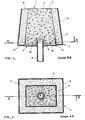
- - la figure 1 représente un élément conforme à l'invention, vu en coupe verticale selon le plan BB de la figure 2,
- - la figure .2 est une vue en section selon le plan horizontal AA de la figure 1.
- FIG. 1 represents an element according to the invention, seen in vertical section along the plane BB of FIG. 2,
- - Figure .2 is a sectional view along the horizontal plane AA of Figure 1.
L'élément représenté sur les figures est constitué par une masse réfractaire 1 logée dans un réceptacle métallique 2, de manière à ne laisser apparaître qu'une surface libre 3. Cette surface libre 3 est destinée à être mise au contact du métal en fusion lorsque l'élément se trouve incorporé au revêtement réfractaire d'un récipient métallurgique.The element shown in the figures is constituted by a
Dans l'exemple décrit, la masse réfractaire 1 est constituée de deux parties l'une dans l'autre: un coeur 4 en matériau réfractaire poreux, perméable au gaz, et une couche périphérique 5, de 2 cm d'épaisseur environ, entourant le coeur 4 et réalisée en un béton réfractaire compact, de très fine granulométrie, de manière à être le plus possible imperméable aux gaz.In the example described, the
Le réceptacle métallique 2, en tôle d'acier doux de 1,5 mm d'épaisseur est composé d'une enveloppe latérale 6 dont une base est fermée par un fond 7 pourvu en son milieu d'une conduite 8 pour l'introduction du gaz de soufflage. On voit que l'enveloppe 6 présente un profil convergent régulier depuis le fond 7 jusqu'au niveau de la surface libre 3, c'est-à-dire dans le sens de soufflage du gaz. Il s'agit là d'une disposition classique, conférant à l'élément une forme en tronc de pyramide à base rectangle ou carrée. On rappelle que cette forme particulière qui n'est pas limitative de l'invention permet d'une part, de faciliter l'insertion sans jeu de l'élément dans l'orifice du revêtement réfractaire destiné à le recevoir et d'autre part, une fois l'élément en place, d'assurer le blocage de la masse réfractaire 1 qui, sinon risque d'être éjectée dans le métal en fusion, sous l'effet du gaz sous pression insufflé par la conduite 8.The
On remarque par ailleurs que, pour obtenir une répartition optimale du gaz dans la masse poreuse 4, il est prévu de ménager à la base de celle-ci un trou borgne 9 définissant une chambre de répartition gazeuse dans laquelle débouche la conduite 8. Cette chambre communique avec un espace de répartition 10 confiné entre le fond 7 et la masse poreuse 4, et s'étendant sur toute la surface de base de cette dernière.We also note that, to obtain an optimal distribution of the gas in the porous mass 4, provision is made to provide at the base thereof a
Conformément à l'objet de l'invention, l'élément présente intérieurement un déflecteur 11 entouré à distance par l'enveloppe 6 et solidaire du fond 7 de façon étanche sur tout son périmètre. Comme le montrent les figures, ce déflecteur est constitué par une cloison métallique parallèle à l'enveloppe 6 mais s'étendant impérativement sur une hauteur inférieure à celle de cette dernière. Des indications plus précises sur la hauteur optimale du déflecteur sont fournies plus loin.In accordance with the object of the invention, the element has internally a
Auparavant, il doit être remarqué que, dans l'exemple décrit, le déflecteur 11 n'est pas rapporté sur le fond 7 mais constitue la petite branche d'un profilé en U asymétrique dont l'enveloppe 6 représente l'autre branche et dont la base, référencée 12, délimite la périphérie du fond 7, la partie centrale de celui-ci étant constituée par un flasque 13 rapporté de façon étanche sur la base 12 au moyen d'un cordon de soudure 14.Beforehand, it should be noted that, in the example described, the
Il est à remarquer également que, conformément à une caractéristique particulière de l'invention, le déflecteur 11 est disposé dans l'élément, de manière à prendre place dans la zone de jonction entre le coeur poreux 4 et la couche compacte 5.It should also be noted that, in accordance with a particular characteristic of the invention, the
On va maintenant décrire un mode de fabrication de l'élément représenté sur les figures. On dispose au départ d'une structure métallique mécanosoudée formant un gouttière rectangulaire fermée sur elle-même et profilée en "U" asymétrique, dont les branches sont parallèles et légèrement inclinées sur la verticale. La grande branche disposée extérieurement représente l'enveloppe 6. La petite branche disposée intérieurement représente le déflecteur 11 et le fond reliant ces deux branches représente la base 12.We will now describe a method of manufacturing the element shown in the figures. At the start, there is a mechanically welded metal structure forming a rectangular gutter closed on itself and asymmetrical "U" shaped, whose branches are parallel and slightly inclined on the vertical. The large branch arranged externally represents the
En règle générale, l'élément devant être réalisé à partir de la structure qui vient d'être décrite, est destiné à se substituer à une brique réfractaire habituelle constitutive du fond de poche d'aciérie ou de convertisseur d'affinage. Il est clair, dans ces conditions, que cette structure présentera avantageusement un gabarit identique ou très légèrement inférieur à celui de la brique à remplacer, dont les formats sont d'ailleurs normalisés. A titre purement indicatif, les briques de fond d'un convertisseur classique ayant une capacité de l'ordre de 20 t. présentent ordinairement le format approché suivant: 60 cm de haut pour une longueur et une largeur respectivement de 16 et 14 cm au niveau de leur base.In general, the element to be made from the structure which has just been described, is intended to replace a brick usual refractory constituting the bottom of a steelworks pocket or refining converter. It is clear, under these conditions, that this structure will advantageously have a size identical to or very slightly lower than that of the brick to be replaced, the formats of which are moreover standardized. For purely indicative purposes, the bottom bricks of a conventional converter having a capacity of the order of 20 t. usually have the following approximate format: 60 cm high for a length and a width of 16 and 14 cm respectively at their base.
On commence par remplir l'espace dis- ponsible entre les deux branches jusqu'a l'extrémité supérieure de la grande branche par un béton réfractaire 5 à grain très fin. Cette opération s'effectue'sans précaution particulière si le béton présente une consistance suffisante. Dans le cas contraire, c'est-à-dire si le béton 5 doit être coulé, il faut prévoir un noyau amovible, que l'on fait momentanément reposer sur le sommet de la petite branche 11, et qui définit avec la grande branche 6 un espace d'épaisseur constante, égale à la largeur de la base 12 de la gouttière. Le béton compact est alors coulé dans cet espace et le noyau est retiré lorsque le béton est devenu suffisamment rigide pour se maintenir de lui-même.We begin by filling the space available between the two branches up to the upper end of the large branch with
La pièce obtenue est retournée, puis posée sur une surface-support fermant temporairement une extrémité de la cavité centrale de la gouttière. Par l'extrémité supérieure laissée ouverte, on remplit cette cavité avec un béton réfractaire poreux 4. On arrête le remplissage un peu avant que le niveau du béton n'atteigne celui de la base 12 de l'U, afin de préserver, dans l'élément achevé, l'espace de répartition gazeux 10. En outre, par tout moyen approprié, on ménage au centre de la masse poreuse un évidement destiné à constituer la chambre de répartition 9.The part obtained is turned over, then placed on a support surface temporarily closing one end of the central cavity of the gutter. By the upper end left open, this cavity is filled with a porous refractory concrete 4. The filling is stopped a little before the level of the concrete reaches that of the
Ces opérations une fois effectuées, on obture l'extrémité de remplissage au moyen d'un flasque métallique 13 rapporté de façon étanche sur la base 12 de la gouttière et portant la conduite 8 d'amenée du gaz de soufflage.Once these operations have been carried out, the filling end is closed off by means of a
L'assemblage étanche entre le flasque 13 et la base 12 est réalisé par un cordon de soudure 14. L'élément ainsi réalisé est alors retiré de la surface support et après séchage et cuisson douce, se trouve prêt à l'emploi.The sealed assembly between the
Les infiltrations de métal en fusion entre l'enveloppe 6 et la couche compacte 5 ne sont alors plus préjudiciables car, au pire, elles atteignent la base du déflecteur 11 en passant sous la couche 5. Ce déflecteur fait alors obstacle à la progression des infiltrations, et les empêche, de ce fait, d'atteindre la conduite de soufflage 8.The infiltration of molten metal between the
Par ailleurs, le déflecteur 11 constitue à l'égard du gaz traversant la masse poreuse 4 une chicane qui le canalise en direction de la surface libre 3 en l'empêchant de se disperser latéralement vers l'enveloppe 6.Furthermore, the
Il doit être noté que, dans l'exemple décrit, la couche de béton compact 5 peut être capable, à elle seule, d'assurer la canalisation du gaz. Toutefois, l'invention ne se limite par à cette forme de réalisation, mais s'étend au cas où toute la masse réfractaire 1 est perméable au gaz et, dans ce cas, seule la chicane 11 assure la canalisation gazeuse.It should be noted that, in the example described, the compact
A cet égard, il pourrait apparaître souhaitable que le déflecteur 11 s'étende sur toute la hauteur de la masse réfractaire 1, c'est-à-dire sur une hauteur égale à celle de l'enveloppe extérieure 6 de manière à canaliser le gaz jusque'à la surface libre 3. En fait, ainsi qu'il a déjà été dit, une telle disposition est à rejeter, car l'extrémité du déflecteur 11 viendrait alors en contact avec le metal en fusion contenu dans le récipient métallurgique et l'on retrouverait à ce niveau tous les problèmes résultant des infiltrations de métal en fuison. En réalité la hauteur optimale pour le déflecteur est sensiblement égale à la hauteur restante de l'ensemble de l'élément, au moment de son remplacement après usure. Cette hauteur optimale est de l'ordre de 15 cm environ dans le cas où le récipient métallurgique auquel est destiné l'élément perméable selon l'invention est un convertisseur d'affinage de la fonte en acier.In this regard, it could appear desirable that the
Il va de soi que la présente invention ne saurait se limiter à l'exemple décrit, mais s'étend à tout autre forme de réalisation du déflecteur dans la masure où il constitue, à l'égard des infiltrations métalliques, une butée d'arrêt et à l'égard du gaz d'insufflation traversant le matériau réfractaire poreux une chicane ou, plus généralement, un organe à très forte perte de charge empêchant ou du moins réduisant fortement la dispersion latérale du gaz jusqu'à l'enveloppe extérieure.It goes without saying that the present invention cannot be limited to the example described, but extends to any other embodiment of the deflector in the hovel where it constitutes, with respect to metal infiltration, a stop and with respect to the blowing gas passing through the porous refractory material, a baffle or, more generally, a member with a very high pressure drop preventing or at least greatly reducing the lateral dispersion of the gas up to the outer envelope.
Claims (7)
Priority Applications (1)
| Application Number | Priority Date | Filing Date | Title |
|---|---|---|---|
| AT80401719T ATE5423T1 (en) | 1979-12-10 | 1980-12-02 | POROUS REFRACTORY ELEMENT AND METHOD OF MANUFACTURE. |
Applications Claiming Priority (2)
| Application Number | Priority Date | Filing Date | Title |
|---|---|---|---|
| FR7930425A FR2471416A1 (en) | 1979-12-10 | 1979-12-10 | POROUS REFRACTORY ELEMENTS AND METHOD OF MANUFACTURE |
| FR7930425 | 1979-12-10 |
Publications (2)
| Publication Number | Publication Date |
|---|---|
| EP0030501A1 EP0030501A1 (en) | 1981-06-17 |
| EP0030501B1 true EP0030501B1 (en) | 1983-11-23 |
Family
ID=9232679
Family Applications (1)
| Application Number | Title | Priority Date | Filing Date |
|---|---|---|---|
| EP80401719A Expired EP0030501B1 (en) | 1979-12-10 | 1980-12-02 | Porous refractory element and its manufacturing method |
Country Status (8)
| Country | Link |
|---|---|
| US (1) | US4348013A (en) |
| EP (1) | EP0030501B1 (en) |
| JP (1) | JPS5694182A (en) |
| AT (1) | ATE5423T1 (en) |
| AU (1) | AU536650B2 (en) |
| CA (1) | CA1160215A (en) |
| DE (1) | DE3065727D1 (en) |
| FR (1) | FR2471416A1 (en) |
Families Citing this family (7)
| Publication number | Priority date | Publication date | Assignee | Title |
|---|---|---|---|---|
| NL189008C (en) * | 1981-11-18 | 1992-12-01 | Hoogovens Groep Bv | Gas-permeable wall element for a metallurgic barrel lined with refractory material, in particular for an L.D. steel converter. |
| FR2516938B1 (en) * | 1981-11-23 | 1986-06-06 | Usinor | DEVICE FOR INTRODUCING GAS INTO THE LIQUID METAL BATH |
| JPS59150656A (en) * | 1983-02-16 | 1984-08-28 | Toshiba Ceramics Co Ltd | Sliding nozzle device |
| DE3503222A1 (en) * | 1985-01-31 | 1986-09-18 | Didier-Werke Ag, 6200 Wiesbaden | Gas-bubbling cone |
| JPH0613254Y2 (en) * | 1988-08-03 | 1994-04-06 | 川崎炉材株式会社 | Molten metal agitator |
| DE4219615C2 (en) * | 1992-06-16 | 1994-05-19 | Burbach & Bender Ohg | Gas purging plug for metallurgical vessels |
| CN109141016B (en) * | 2018-06-01 | 2019-08-16 | 福建麦特新铝业科技有限公司 | A kind of porous plug and metal smelting-furnace for the air agitation of smelting furnace bottom |
Citations (3)
| Publication number | Priority date | Publication date | Assignee | Title |
|---|---|---|---|---|
| US2811346A (en) * | 1952-01-21 | 1957-10-29 | L Air Liquide Sa Pour L Etudes | Device for insufflating gas into a mass of molten metal |
| FR1162727A (en) * | 1956-10-26 | 1958-09-16 | Siderurgie Fse Inst Rech | Process for obtaining porous concrete parts ensuring the directed blowing of a fluid and products obtained by means of this process |
| DE2633054B1 (en) * | 1976-06-01 | 1977-09-15 | Alusuisse | Device for introducing gases into reaction vessels containing liquids |
Family Cites Families (4)
| Publication number | Priority date | Publication date | Assignee | Title |
|---|---|---|---|---|
| LU30391A1 (en) * | 1949-11-03 | |||
| FR1031504A (en) * | 1957-09-09 | 1953-06-24 | Air Liquide | Device for blowing gas into a mass of molten metal |
| US3633898A (en) * | 1969-06-06 | 1972-01-11 | Stora Kopparbergs Bergslags Ab | Means for gas-flushing metal melts |
| US3610602A (en) * | 1969-10-14 | 1971-10-05 | United States Steel Corp | Gas-permeable refractory plug and method |
-
1979
- 1979-12-10 FR FR7930425A patent/FR2471416A1/en active Granted
-
1980
- 1980-12-02 EP EP80401719A patent/EP0030501B1/en not_active Expired
- 1980-12-02 DE DE8080401719T patent/DE3065727D1/en not_active Expired
- 1980-12-02 AT AT80401719T patent/ATE5423T1/en not_active IP Right Cessation
- 1980-12-02 AU AU64996/80A patent/AU536650B2/en not_active Ceased
- 1980-12-03 CA CA000366053A patent/CA1160215A/en not_active Expired
- 1980-12-05 US US06/213,548 patent/US4348013A/en not_active Expired - Lifetime
- 1980-12-09 JP JP17268780A patent/JPS5694182A/en active Pending
Patent Citations (3)
| Publication number | Priority date | Publication date | Assignee | Title |
|---|---|---|---|---|
| US2811346A (en) * | 1952-01-21 | 1957-10-29 | L Air Liquide Sa Pour L Etudes | Device for insufflating gas into a mass of molten metal |
| FR1162727A (en) * | 1956-10-26 | 1958-09-16 | Siderurgie Fse Inst Rech | Process for obtaining porous concrete parts ensuring the directed blowing of a fluid and products obtained by means of this process |
| DE2633054B1 (en) * | 1976-06-01 | 1977-09-15 | Alusuisse | Device for introducing gases into reaction vessels containing liquids |
Also Published As
| Publication number | Publication date |
|---|---|
| EP0030501A1 (en) | 1981-06-17 |
| JPS5694182A (en) | 1981-07-30 |
| DE3065727D1 (en) | 1983-12-29 |
| CA1160215A (en) | 1984-01-10 |
| AU536650B2 (en) | 1984-05-17 |
| ATE5423T1 (en) | 1983-12-15 |
| US4348013A (en) | 1982-09-07 |
| FR2471416B1 (en) | 1985-03-22 |
| FR2471416A1 (en) | 1981-06-19 |
| AU6499680A (en) | 1981-06-18 |
Similar Documents
| Publication | Publication Date | Title |
|---|---|---|
| EP0021861B2 (en) | Gas-permeable refractory block and method of making this block | |
| EP0030501B1 (en) | Porous refractory element and its manufacturing method | |
| EP0094926B1 (en) | Orifice for injecting a protecting gas into a casting tube | |
| EP2229259B1 (en) | Mould for direct-cast aluminothermic welding | |
| EP0567374B1 (en) | Dispensing cap for liquid or pastry products | |
| EP2371471A1 (en) | Internal nozzle for transferring liquid metal contained in a container, system for clamping said nozzle and pouring device | |
| CH630274A5 (en) | COOLING SHIRT FOR CONTINUOUS CASTING LINGOTIERE. | |
| EP0404641B1 (en) | Tundish for continuous casting steel | |
| EP0080403B1 (en) | Installation for introducing gas into a bath of liquid metal | |
| FR2601606A1 (en) | REFRACTORY LINK BY CHANNEL FOR THE ROUTING OF MOLTEN STEEL IN CONTINUOUS CASTING MACHINES HAVING A CASTING WHEEL. | |
| EP0585254B1 (en) | Sealing belt for a casting tube | |
| FR2551374A1 (en) | DEVICE FOR REFRACTORY PLATES OF SLIDING SHUTTERS | |
| EP0198123A1 (en) | Method of sealing junction canals for liquid metal and canals sealed by using this method | |
| FR2627467A1 (en) | Floating lid for liquid vat - has conical cover with rim seal and central venting valve | |
| FR2540759A1 (en) | Casting ladle slide valve for teeming | |
| FR2543576A1 (en) | METHOD AND INSTALLATION FOR SCANNING A METAL BATH FILLED IN PARTICULAR FROM STEEL IN A CASTING POUCH OR THE LIKE PROVIDED WITH A SHUTTER PLUG | |
| FR2552749A1 (en) | Device for the automatic filling of bottles, particularly with carbonated liquids | |
| FR2701412A1 (en) | Novel-type pouring (casting) ladle | |
| FR2749279A1 (en) | Protection from atmosphere of wine contained in barrels | |
| BE1001239A3 (en) | Metallurgical vessel sliding closure - made airtight by grooved metal band providing inert gas shroud | |
| EP0578596A1 (en) | Furnace, in particular electric furnace for the treatment of molten metal | |
| EP0171487B1 (en) | Device for the external closing of a vessel for molten metal | |
| EP0332490A1 (en) | Ladle for transporting especially liquid metals | |
| FR2721325A1 (en) | Permanent device for emptying channels and metallurgical apparatus and its use. | |
| EP0836539A1 (en) | Internal nozzle/plate assembly comprising a weakened portion |
Legal Events
| Date | Code | Title | Description |
|---|---|---|---|
| PUAI | Public reference made under article 153(3) epc to a published international application that has entered the european phase |
Free format text: ORIGINAL CODE: 0009012 |
|
| AK | Designated contracting states |
Designated state(s): AT BE DE FR GB IT LU NL SE |
|
| ITCL | It: translation for ep claims filed |
Representative=s name: BARZANO' E ZANARDO MILANO S.P.A. |
|
| TCAT | At: translation of patent claims filed | ||
| DET | De: translation of patent claims | ||
| 17P | Request for examination filed |
Effective date: 19811209 |
|
| ITF | It: translation for a ep patent filed |
Owner name: BARZANO' E ZANARDO MILANO S.P.A. |
|
| GRAA | (expected) grant |
Free format text: ORIGINAL CODE: 0009210 |
|
| AK | Designated contracting states |
Designated state(s): AT BE DE FR GB IT LU NL SE |
|
| REF | Corresponds to: |
Ref document number: 5423 Country of ref document: AT Date of ref document: 19831215 Kind code of ref document: T |
|
| PGFP | Annual fee paid to national office [announced via postgrant information from national office to epo] |
Ref country code: LU Payment date: 19831207 Year of fee payment: 4 |
|
| REF | Corresponds to: |
Ref document number: 3065727 Country of ref document: DE Date of ref document: 19831229 |
|
| PG25 | Lapsed in a contracting state [announced via postgrant information from national office to epo] |
Ref country code: LU Free format text: LAPSE BECAUSE OF NON-PAYMENT OF DUE FEES Effective date: 19831231 |
|
| PLBI | Opposition filed |
Free format text: ORIGINAL CODE: 0009260 |
|
| PGFP | Annual fee paid to national office [announced via postgrant information from national office to epo] |
Ref country code: SE Payment date: 19840930 Year of fee payment: 5 Ref country code: BE Payment date: 19840930 Year of fee payment: 5 |
|
| 26 | Opposition filed |
Opponent name: DIDIER-WERKE AG Effective date: 19840821 |
|
| PLBN | Opposition rejected |
Free format text: ORIGINAL CODE: 0009273 |
|
| STAA | Information on the status of an ep patent application or granted ep patent |
Free format text: STATUS: OPPOSITION REJECTED |
|
| 27O | Opposition rejected |
Effective date: 19850312 |
|
| NLR2 | Nl: decision of opposition | ||
| PGFP | Annual fee paid to national office [announced via postgrant information from national office to epo] |
Ref country code: NL Payment date: 19861231 Year of fee payment: 7 |
|
| PG25 | Lapsed in a contracting state [announced via postgrant information from national office to epo] |
Ref country code: SE Effective date: 19871203 |
|
| PG25 | Lapsed in a contracting state [announced via postgrant information from national office to epo] |
Ref country code: NL Effective date: 19880701 |
|
| GBPC | Gb: european patent ceased through non-payment of renewal fee | ||
| NLV4 | Nl: lapsed or anulled due to non-payment of the annual fee | ||
| PG25 | Lapsed in a contracting state [announced via postgrant information from national office to epo] |
Ref country code: GB Effective date: 19881118 |
|
| PG25 | Lapsed in a contracting state [announced via postgrant information from national office to epo] |
Ref country code: BE Effective date: 19881231 |
|
| BERE | Be: lapsed |
Owner name: INSTITUT DE RECHERCHES DE LA SIDERURGIE FRANCAISE Effective date: 19881231 |
|
| ITTA | It: last paid annual fee | ||
| EUG | Se: european patent has lapsed |
Ref document number: 80401719.2 Effective date: 19880912 |
|
| PGFP | Annual fee paid to national office [announced via postgrant information from national office to epo] |
Ref country code: FR Payment date: 19971113 Year of fee payment: 18 |
|
| PGFP | Annual fee paid to national office [announced via postgrant information from national office to epo] |
Ref country code: AT Payment date: 19971126 Year of fee payment: 18 |
|
| PGFP | Annual fee paid to national office [announced via postgrant information from national office to epo] |
Ref country code: DE Payment date: 19971128 Year of fee payment: 18 |
|
| PG25 | Lapsed in a contracting state [announced via postgrant information from national office to epo] |
Ref country code: AT Free format text: LAPSE BECAUSE OF NON-PAYMENT OF DUE FEES Effective date: 19981202 |
|
| PG25 | Lapsed in a contracting state [announced via postgrant information from national office to epo] |
Ref country code: FR Free format text: LAPSE BECAUSE OF NON-PAYMENT OF DUE FEES Effective date: 19990831 |
|
| REG | Reference to a national code |
Ref country code: FR Ref legal event code: ST |
|
| PG25 | Lapsed in a contracting state [announced via postgrant information from national office to epo] |
Ref country code: DE Free format text: LAPSE BECAUSE OF NON-PAYMENT OF DUE FEES Effective date: 19991001 |