EP0030501B1 - Poröses feuerfestes Element und Verfahren zur Herstellung - Google Patents
Poröses feuerfestes Element und Verfahren zur Herstellung Download PDFInfo
- Publication number
- EP0030501B1 EP0030501B1 EP80401719A EP80401719A EP0030501B1 EP 0030501 B1 EP0030501 B1 EP 0030501B1 EP 80401719 A EP80401719 A EP 80401719A EP 80401719 A EP80401719 A EP 80401719A EP 0030501 B1 EP0030501 B1 EP 0030501B1
- Authority
- EP
- European Patent Office
- Prior art keywords
- refractory
- gas
- trough
- mass
- porous
- Prior art date
- Legal status (The legal status is an assumption and is not a legal conclusion. Google has not performed a legal analysis and makes no representation as to the accuracy of the status listed.)
- Expired
Links
- 238000004519 manufacturing process Methods 0.000 title claims abstract description 10
- 239000002184 metal Substances 0.000 claims description 23
- 229910052751 metal Inorganic materials 0.000 claims description 23
- 230000002093 peripheral effect Effects 0.000 claims description 7
- 238000000034 method Methods 0.000 claims description 3
- 239000011796 hollow space material Substances 0.000 claims 3
- 238000007664 blowing Methods 0.000 abstract description 10
- 239000011819 refractory material Substances 0.000 abstract description 5
- 230000035515 penetration Effects 0.000 abstract description 2
- 229910001338 liquidmetal Inorganic materials 0.000 abstract 2
- 239000007789 gas Substances 0.000 description 28
- 230000008595 infiltration Effects 0.000 description 6
- 238000001764 infiltration Methods 0.000 description 6
- 229910000831 Steel Inorganic materials 0.000 description 3
- 239000011449 brick Substances 0.000 description 3
- 239000010959 steel Substances 0.000 description 3
- 239000011324 bead Substances 0.000 description 2
- 230000000903 blocking effect Effects 0.000 description 2
- 239000012530 fluid Substances 0.000 description 2
- 238000000465 moulding Methods 0.000 description 2
- 238000007670 refining Methods 0.000 description 2
- 238000007789 sealing Methods 0.000 description 2
- 229910001018 Cast iron Inorganic materials 0.000 description 1
- 230000015556 catabolic process Effects 0.000 description 1
- 230000005465 channeling Effects 0.000 description 1
- 238000010411 cooking Methods 0.000 description 1
- 238000006731 degradation reaction Methods 0.000 description 1
- 238000007599 discharging Methods 0.000 description 1
- 239000006185 dispersion Substances 0.000 description 1
- 238000001035 drying Methods 0.000 description 1
- 230000000694 effects Effects 0.000 description 1
- 230000001747 exhibiting effect Effects 0.000 description 1
- 238000002474 experimental method Methods 0.000 description 1
- 239000010419 fine particle Substances 0.000 description 1
- 238000003780 insertion Methods 0.000 description 1
- 230000037431 insertion Effects 0.000 description 1
- 239000002245 particle Substances 0.000 description 1
- 238000005192 partition Methods 0.000 description 1
- 230000035699 permeability Effects 0.000 description 1
- 230000002787 reinforcement Effects 0.000 description 1
- 230000003252 repetitive effect Effects 0.000 description 1
- 230000000284 resting effect Effects 0.000 description 1
- 230000035939 shock Effects 0.000 description 1
Images
Classifications
-
- B—PERFORMING OPERATIONS; TRANSPORTING
- B22—CASTING; POWDER METALLURGY
- B22D—CASTING OF METALS; CASTING OF OTHER SUBSTANCES BY THE SAME PROCESSES OR DEVICES
- B22D1/00—Treatment of fused masses in the ladle or the supply runners before casting
- B22D1/002—Treatment with gases
- B22D1/005—Injection assemblies therefor
-
- C—CHEMISTRY; METALLURGY
- C21—METALLURGY OF IRON
- C21C—PROCESSING OF PIG-IRON, e.g. REFINING, MANUFACTURE OF WROUGHT-IRON OR STEEL; TREATMENT IN MOLTEN STATE OF FERROUS ALLOYS
- C21C5/00—Manufacture of carbon-steel, e.g. plain mild steel, medium carbon steel or cast steel or stainless steel
- C21C5/28—Manufacture of steel in the converter
- C21C5/42—Constructional features of converters
- C21C5/46—Details or accessories
- C21C5/48—Bottoms or tuyéres of converters
-
- C—CHEMISTRY; METALLURGY
- C22—METALLURGY; FERROUS OR NON-FERROUS ALLOYS; TREATMENT OF ALLOYS OR NON-FERROUS METALS
- C22B—PRODUCTION AND REFINING OF METALS; PRETREATMENT OF RAW MATERIALS
- C22B9/00—General processes of refining or remelting of metals; Apparatus for electroslag or arc remelting of metals
- C22B9/05—Refining by treating with gases, e.g. gas flushing also refining by means of a material generating gas in situ
Definitions
- the present invention relates to porous refractory elements intended to be traversed by a gaseous fluid under pressure.
- a metal casing for example a thin steel sheet, which is closed at one of its ends by a base plate provided with supply means. blowing gas.
- the envelope and the plate define a receptacle in which the porous mass only appears by a single free face, which is intended to be brought into contact with the molten metal.
- the inventors have found that, under the influence of repetitive blowing sequences, the envelope sometimes ends up exhibiting permanent deformation, so that in the absence of blowing, molten metal entered the. spaces thus formed between the envelope and the porous mass.
- the invention relates to a porous refractory element intended to be traversed by a gaseous fluid under pressure and comprising a porous refractory mass placed in a metal receptacle constituted by a lateral envelope and a base plate provided with means gas supply, characterized in that the receptacle internally comprises a deflector secured to the base plate and the walls of which parallel to the lateral envelope extend over a height less than that of said envelope.
- the deflector consists of a simple metallic ferrule.
- the refractory mass is composed of a porous central part surrounded by a peripheral layer of compact refractory concrete, the deflector taking position between this central part and the peripheral layer.
- the subject of the invention is also a method of manufacturing the porous refractory element, according to which the metal receptacle constitutes the shell for molding the refractory mass, a method characterized in that it consists in taking an asymmetrical U-shaped metal gutter whose large branch, arranged externally, constitutes the lateral envelope and the small branch constitutes the deflector, to fill this gutter with a compact refractory concrete so as to obtain a sealed peripheral layer, to invert the assembly obtained and to place it on a temporary support surface, then filling the remaining central cavity with porous refractory concrete and finally closing the filling orifice with a plate fitted with gas supply means and fixed in leaktight manner to the base of the gutter.
- the present invention therefore basically consists in discharging the metal envelope from its lateral gas-tightness function by replacing, for this purpose, an internal deflector surrounded at a distance by said envelope. Fixing the deflector on the base plate allows it, moreover, to constitute a stop against the infiltrations of molten metal which take place between the envelope and the porous mass and to prevent these from coming to obstruct the means for supplying the blowing gas.
- the deflector only partially replaces the casing in its role of lateral gas tightness.
- the deflector can in fact only constitute a baffle having a reduced height compared to that of the envelope. It is understood that, in the opposite case, that is to say if the deflector extended from the base plate to the free surface of the porous mass, we would otherwise be in a situation analogous to that known described previously with the drawbacks which the present invention seeks to remedy precisely.
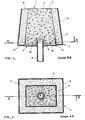
- the element shown in the figures is constituted by a refractory mass 1 housed in a metal receptacle 2, so as to reveal only a free surface 3.
- This free surface 3 is intended to be brought into contact with the molten metal when the element is incorporated into the refractory lining of a metallurgical container.
- the refractory mass 1 is made up of two parts, one inside the other: a core 4 made of porous refractory material, permeable to gas, and a peripheral layer 5, about 2 cm thick, surrounding the core 4 and made of a compact refractory concrete, of very fine particle size, so as to be as impermeable to gases as possible.
- the metal receptacle 2 made of 1.5 mm thick sheet steel, is composed of a lateral envelope 6, a base of which is closed by a bottom 7 provided in the middle with a pipe 8 for the introduction of the blowing gas.
- the envelope 6 has a regular converging profile from the bottom 7 to the level of the free surface 3, that is to say in the direction of blowing of the gas. This is a classic arrangement, giving the element a shape in the form of a pyramid with a rectangular or square base.
- this particular form which is not limitative of the invention makes it possible, on the one hand, to facilitate the insertion without play of the element in the orifice of the refractory lining intended to receive it and, on the other hand, once the element is in place, ensure the blocking of the refractory mass 1 which otherwise risks being ejected into the molten metal, under the effect of the pressurized gas blown through the pipe 8.
- the element has internally a deflector 11 surrounded at a distance by the casing 6 and secured to the bottom 7 in a sealed manner over its entire perimeter.
- this deflector is constituted by a metal partition parallel to the casing 6 but necessarily extending over a height less than that of the latter. More precise information on the optimal height of the deflector is given below.
- the deflector 11 is not attached to the bottom 7 but constitutes the small branch of an asymmetrical U-shaped section whose casing 6 represents the other branch and whose the base, referenced 12, delimits the periphery of the bottom 7, the central part of the latter being constituted by a flange 13 sealingly attached to the base 12 by means of a weld bead 14.
- the deflector 11 is disposed in the element, so as to take place in the junction zone between the porous core 4 and the compact layer 5.
- the element to be made from the structure which has just been described is intended to replace a brick usual refractory constituting the bottom of a steelworks pocket or refining converter. It is clear, under these conditions, that this structure will advantageously have a size identical to or very slightly lower than that of the brick to be replaced, the formats of which are moreover standardized.
- the bottom bricks of a conventional converter having a capacity of the order of 20 t. usually have the following approximate format: 60 cm high for a length and a width of 16 and 14 cm respectively at their base.
- the filling end is closed off by means of a metal flange 13 sealingly attached to the base 12 of the gutter and carrying the pipe 8 for supplying the blowing gas.
- the sealed assembly between the flange 13 and the base 12 is produced by a weld bead 14.
- the element thus produced is then removed from the support surface and after drying and gentle cooking, is ready for use.
- the deflector 11 constitutes with respect to the gas passing through the porous mass 4 a baffle which channels it towards the free surface 3 by preventing it from dispersing laterally towards the envelope 6.
- the compact concrete layer 5 may be capable, by itself, of ensuring the channeling of the gas.
- the invention is not limited to this embodiment, but extends to the case where the entire refractory mass 1 is permeable to gas and, in this case, only the baffle 11 ensures the gas pipeline.
- the deflector 11 extends over the entire height of the refractory mass 1, that is to say over a height equal to that of the outer casing 6 so as to channel the gas up to the free surface 3.
- the optimum height for the deflector is substantially equal to the remaining height of the entire element, when it is replaced after wear. This optimal height is of the order of approximately 15 cm in the case where the metallurgical container for which the permeable element according to the invention is intended is a converter for refining cast iron into steel.
- the present invention cannot be limited to the example described, but extends to any other embodiment of the deflector in the hovel where it constitutes, with respect to metal infiltration, a stop and with respect to the blowing gas passing through the porous refractory material, a baffle or, more generally, a member with a very high pressure drop preventing or at least greatly reducing the lateral dispersion of the gas up to the outer envelope.
Landscapes
- Engineering & Computer Science (AREA)
- Chemical & Material Sciences (AREA)
- Manufacturing & Machinery (AREA)
- Materials Engineering (AREA)
- Mechanical Engineering (AREA)
- Metallurgy (AREA)
- Organic Chemistry (AREA)
- Treatment Of Steel In Its Molten State (AREA)
- Casting Support Devices, Ladles, And Melt Control Thereby (AREA)
- Carbon Steel Or Casting Steel Manufacturing (AREA)
- Magnetic Heads (AREA)
- Manufacture And Refinement Of Metals (AREA)
- Manufacturing Of Tubular Articles Or Embedded Moulded Articles (AREA)
- Furnace Charging Or Discharging (AREA)
- Filtering Materials (AREA)
- Separation Using Semi-Permeable Membranes (AREA)
- Continuous Casting (AREA)
Claims (7)
Priority Applications (1)
| Application Number | Priority Date | Filing Date | Title |
|---|---|---|---|
| AT80401719T ATE5423T1 (de) | 1979-12-10 | 1980-12-02 | Poroeses feuerfestes element und verfahren zur herstellung. |
Applications Claiming Priority (2)
| Application Number | Priority Date | Filing Date | Title |
|---|---|---|---|
| FR7930425 | 1979-12-10 | ||
| FR7930425A FR2471416A1 (fr) | 1979-12-10 | 1979-12-10 | Elements refractaires poreux et procede de fabrication |
Publications (2)
| Publication Number | Publication Date |
|---|---|
| EP0030501A1 EP0030501A1 (de) | 1981-06-17 |
| EP0030501B1 true EP0030501B1 (de) | 1983-11-23 |
Family
ID=9232679
Family Applications (1)
| Application Number | Title | Priority Date | Filing Date |
|---|---|---|---|
| EP80401719A Expired EP0030501B1 (de) | 1979-12-10 | 1980-12-02 | Poröses feuerfestes Element und Verfahren zur Herstellung |
Country Status (8)
| Country | Link |
|---|---|
| US (1) | US4348013A (de) |
| EP (1) | EP0030501B1 (de) |
| JP (1) | JPS5694182A (de) |
| AT (1) | ATE5423T1 (de) |
| AU (1) | AU536650B2 (de) |
| CA (1) | CA1160215A (de) |
| DE (1) | DE3065727D1 (de) |
| FR (1) | FR2471416A1 (de) |
Families Citing this family (7)
| Publication number | Priority date | Publication date | Assignee | Title |
|---|---|---|---|---|
| NL189008C (nl) * | 1981-11-18 | 1992-12-01 | Hoogovens Groep Bv | Gasdoorlatend wandelement voor een met vuurvast materiaal bekleed metallurgisch vat, in het bijzonder voor een l.d.-staalconverter. |
| FR2516938B1 (fr) * | 1981-11-23 | 1986-06-06 | Usinor | Dispositif pour l'introduction de gaz dans le bain de metal liquide |
| JPS59150656A (ja) * | 1983-02-16 | 1984-08-28 | Toshiba Ceramics Co Ltd | スライデイングノズル装置 |
| DE3503222A1 (de) * | 1985-01-31 | 1986-09-18 | Didier-Werke Ag, 6200 Wiesbaden | Gasspuelkegel |
| JPH0613254Y2 (ja) * | 1988-08-03 | 1994-04-06 | 川崎炉材株式会社 | 溶融金属撹拌装置 |
| DE4219615C2 (de) * | 1992-06-16 | 1994-05-19 | Burbach & Bender Ohg | Gasspülstein für metallurgische Gefäße |
| CN109141016B (zh) * | 2018-06-01 | 2019-08-16 | 福建麦特新铝业科技有限公司 | 一种用于熔炼炉炉底通气搅拌的透气塞及金属熔炼炉 |
Citations (3)
| Publication number | Priority date | Publication date | Assignee | Title |
|---|---|---|---|---|
| US2811346A (en) * | 1952-01-21 | 1957-10-29 | L Air Liquide Sa Pour L Etudes | Device for insufflating gas into a mass of molten metal |
| FR1162727A (fr) * | 1956-10-26 | 1958-09-16 | Siderurgie Fse Inst Rech | Procédé pour obtenir des pièces en béton poreux assurant l'insufflation dirigée d'un fluide et produits obtenus au moyen de ce procédé |
| DE2633054B1 (de) * | 1976-06-01 | 1977-09-15 | Alusuisse | Vorrichtung zur Einleitung von Gasen in Fluessigkeiten enthaltende Reaktionsgefaesse |
Family Cites Families (4)
| Publication number | Priority date | Publication date | Assignee | Title |
|---|---|---|---|---|
| LU30391A1 (de) * | 1949-11-03 | |||
| FR1031504A (fr) * | 1957-09-09 | 1953-06-24 | Air Liquide | Dispositif d'insufflation de gaz dans une masse de métal fondu |
| US3633898A (en) * | 1969-06-06 | 1972-01-11 | Stora Kopparbergs Bergslags Ab | Means for gas-flushing metal melts |
| US3610602A (en) * | 1969-10-14 | 1971-10-05 | United States Steel Corp | Gas-permeable refractory plug and method |
-
1979
- 1979-12-10 FR FR7930425A patent/FR2471416A1/fr active Granted
-
1980
- 1980-12-02 AT AT80401719T patent/ATE5423T1/de not_active IP Right Cessation
- 1980-12-02 AU AU64996/80A patent/AU536650B2/en not_active Ceased
- 1980-12-02 EP EP80401719A patent/EP0030501B1/de not_active Expired
- 1980-12-02 DE DE8080401719T patent/DE3065727D1/de not_active Expired
- 1980-12-03 CA CA000366053A patent/CA1160215A/fr not_active Expired
- 1980-12-05 US US06/213,548 patent/US4348013A/en not_active Expired - Lifetime
- 1980-12-09 JP JP17268780A patent/JPS5694182A/ja active Pending
Patent Citations (3)
| Publication number | Priority date | Publication date | Assignee | Title |
|---|---|---|---|---|
| US2811346A (en) * | 1952-01-21 | 1957-10-29 | L Air Liquide Sa Pour L Etudes | Device for insufflating gas into a mass of molten metal |
| FR1162727A (fr) * | 1956-10-26 | 1958-09-16 | Siderurgie Fse Inst Rech | Procédé pour obtenir des pièces en béton poreux assurant l'insufflation dirigée d'un fluide et produits obtenus au moyen de ce procédé |
| DE2633054B1 (de) * | 1976-06-01 | 1977-09-15 | Alusuisse | Vorrichtung zur Einleitung von Gasen in Fluessigkeiten enthaltende Reaktionsgefaesse |
Also Published As
| Publication number | Publication date |
|---|---|
| AU536650B2 (en) | 1984-05-17 |
| DE3065727D1 (en) | 1983-12-29 |
| JPS5694182A (en) | 1981-07-30 |
| AU6499680A (en) | 1981-06-18 |
| FR2471416A1 (fr) | 1981-06-19 |
| EP0030501A1 (de) | 1981-06-17 |
| ATE5423T1 (de) | 1983-12-15 |
| FR2471416B1 (de) | 1985-03-22 |
| US4348013A (en) | 1982-09-07 |
| CA1160215A (fr) | 1984-01-10 |
Similar Documents
| Publication | Publication Date | Title |
|---|---|---|
| EP0030501B1 (de) | Poröses feuerfestes Element und Verfahren zur Herstellung | |
| EP0094926B1 (de) | Mündung zum Einführen eines Schutzgases in ein Giessrohr | |
| EP2229259B1 (de) | Form zum aluminium-thermoschweissen mit direktem guss | |
| EP0567374B1 (de) | Spenderkappe für flüssige oder pastöse Produkte | |
| CH630274A5 (fr) | Chemise de refroidissement pour lingotiere de coulee continue. | |
| EP2371471A1 (de) | Interne Düse für den Transfer von flüssigem Metall in einem Behälter, Einspannsystem für diese Düse und Ausflussvorrichtung | |
| EP0404641B1 (de) | Verteiler zum Stranggiessen von Stahl | |
| EP0080403B1 (de) | Einrichtung zum Einführen von Gas in ein Metallbad | |
| FR2601606A1 (fr) | Liaison refractaire par canal pour l'acheminement d'acier en fusion dans des machines de coulee continue comportant une roue de coulee. | |
| EP0585254B1 (de) | Dichtband für giessrohr | |
| FR2551374A1 (fr) | Dispositif pour plaques refractaires d'obturateurs coulissants | |
| FR2767082A1 (fr) | Busette de coulee pour le transfert d'un metal liquide d'un repartiteur dans une lingotiere | |
| EP2490842B1 (de) | Verfahren zur herstellung eines metallblocks mit einer bohrung sowie entsprechender metallblock und pressform | |
| EP0198123A1 (de) | Verfahren zum Abdichten von Verbindungsleitungen für flüssiges Metall und Leitungen, abgedichtet unter Anwendung dieses Verfahrens | |
| FR2627467A1 (fr) | Couvercle flottant pour recipient a liquide, notamment pour recipient a vin | |
| FR2629101A1 (fr) | Brique pour l'introduction de gaz ou de produits de reaction dans un recipient de coulee metallurgique | |
| FR2540759A1 (fr) | Glissiere perfectionnee equipant une poche de coulee ou conteneur analogue | |
| FR2543576A1 (fr) | Procede et installation pour le balayage d'un bain de metal fondu notamment d'acier dans une poche de coulee ou analogue munie d'un bouchon d'obturation | |
| FR2552749A1 (fr) | Dispositif de remplissage automatique de bouteilles, notamment par des liquides carbonates | |
| FR2701412A1 (fr) | Poche de coulée d'un nouveau type. | |
| FR2749279A1 (fr) | Dispositif pour maintenir a l'abri de tout contact avec l'atmosphere le vin contenu dans une barique ou tonneau malgre la baisse de niveau due a l'absorption des parois de bois | |
| BE1001239A3 (fr) | Procede pour rendre etanche a l'air une fermeture coulissante et plaque refractaire d'usure prevue a cet effet. | |
| EP0578596A1 (de) | Ofen, insbesondere elektrische Ofen für die Behandlung von geschmolzen Metallen | |
| EP0171487B1 (de) | Vorrichtung zum Aussenabschluss eines Gefässes für schmelzflüssige Metalle | |
| EP0332490A1 (de) | Pfanne zum Transport von flüssigen Metallen |
Legal Events
| Date | Code | Title | Description |
|---|---|---|---|
| PUAI | Public reference made under article 153(3) epc to a published international application that has entered the european phase |
Free format text: ORIGINAL CODE: 0009012 |
|
| AK | Designated contracting states |
Designated state(s): AT BE DE FR GB IT LU NL SE |
|
| ITCL | It: translation for ep claims filed |
Representative=s name: BARZANO' E ZANARDO MILANO S.P.A. |
|
| TCAT | At: translation of patent claims filed | ||
| DET | De: translation of patent claims | ||
| 17P | Request for examination filed |
Effective date: 19811209 |
|
| ITF | It: translation for a ep patent filed |
Owner name: BARZANO' E ZANARDO MILANO S.P.A. |
|
| GRAA | (expected) grant |
Free format text: ORIGINAL CODE: 0009210 |
|
| AK | Designated contracting states |
Designated state(s): AT BE DE FR GB IT LU NL SE |
|
| REF | Corresponds to: |
Ref document number: 5423 Country of ref document: AT Date of ref document: 19831215 Kind code of ref document: T |
|
| PGFP | Annual fee paid to national office [announced via postgrant information from national office to epo] |
Ref country code: LU Payment date: 19831207 Year of fee payment: 4 |
|
| REF | Corresponds to: |
Ref document number: 3065727 Country of ref document: DE Date of ref document: 19831229 |
|
| PG25 | Lapsed in a contracting state [announced via postgrant information from national office to epo] |
Ref country code: LU Free format text: LAPSE BECAUSE OF NON-PAYMENT OF DUE FEES Effective date: 19831231 |
|
| PLBI | Opposition filed |
Free format text: ORIGINAL CODE: 0009260 |
|
| PGFP | Annual fee paid to national office [announced via postgrant information from national office to epo] |
Ref country code: SE Payment date: 19840930 Year of fee payment: 5 Ref country code: BE Payment date: 19840930 Year of fee payment: 5 |
|
| 26 | Opposition filed |
Opponent name: DIDIER-WERKE AG Effective date: 19840821 |
|
| PLBN | Opposition rejected |
Free format text: ORIGINAL CODE: 0009273 |
|
| STAA | Information on the status of an ep patent application or granted ep patent |
Free format text: STATUS: OPPOSITION REJECTED |
|
| 27O | Opposition rejected |
Effective date: 19850312 |
|
| NLR2 | Nl: decision of opposition | ||
| PGFP | Annual fee paid to national office [announced via postgrant information from national office to epo] |
Ref country code: NL Payment date: 19861231 Year of fee payment: 7 |
|
| PG25 | Lapsed in a contracting state [announced via postgrant information from national office to epo] |
Ref country code: SE Effective date: 19871203 |
|
| PG25 | Lapsed in a contracting state [announced via postgrant information from national office to epo] |
Ref country code: NL Effective date: 19880701 |
|
| GBPC | Gb: european patent ceased through non-payment of renewal fee | ||
| NLV4 | Nl: lapsed or anulled due to non-payment of the annual fee | ||
| PG25 | Lapsed in a contracting state [announced via postgrant information from national office to epo] |
Ref country code: GB Effective date: 19881118 |
|
| PG25 | Lapsed in a contracting state [announced via postgrant information from national office to epo] |
Ref country code: BE Effective date: 19881231 |
|
| BERE | Be: lapsed |
Owner name: INSTITUT DE RECHERCHES DE LA SIDERURGIE FRANCAISE Effective date: 19881231 |
|
| ITTA | It: last paid annual fee | ||
| EUG | Se: european patent has lapsed |
Ref document number: 80401719.2 Effective date: 19880912 |
|
| PGFP | Annual fee paid to national office [announced via postgrant information from national office to epo] |
Ref country code: FR Payment date: 19971113 Year of fee payment: 18 |
|
| PGFP | Annual fee paid to national office [announced via postgrant information from national office to epo] |
Ref country code: AT Payment date: 19971126 Year of fee payment: 18 |
|
| PGFP | Annual fee paid to national office [announced via postgrant information from national office to epo] |
Ref country code: DE Payment date: 19971128 Year of fee payment: 18 |
|
| PG25 | Lapsed in a contracting state [announced via postgrant information from national office to epo] |
Ref country code: AT Free format text: LAPSE BECAUSE OF NON-PAYMENT OF DUE FEES Effective date: 19981202 |
|
| PG25 | Lapsed in a contracting state [announced via postgrant information from national office to epo] |
Ref country code: FR Free format text: LAPSE BECAUSE OF NON-PAYMENT OF DUE FEES Effective date: 19990831 |
|
| REG | Reference to a national code |
Ref country code: FR Ref legal event code: ST |
|
| PG25 | Lapsed in a contracting state [announced via postgrant information from national office to epo] |
Ref country code: DE Free format text: LAPSE BECAUSE OF NON-PAYMENT OF DUE FEES Effective date: 19991001 |