EP0029518B1 - Appareil d'électrolyse à électrodes bipolaires, notamment pour l'électrolyse des solutions salines, avec obtention d'hypochlorite - Google Patents
Appareil d'électrolyse à électrodes bipolaires, notamment pour l'électrolyse des solutions salines, avec obtention d'hypochlorite Download PDFInfo
- Publication number
- EP0029518B1 EP0029518B1 EP80106641A EP80106641A EP0029518B1 EP 0029518 B1 EP0029518 B1 EP 0029518B1 EP 80106641 A EP80106641 A EP 80106641A EP 80106641 A EP80106641 A EP 80106641A EP 0029518 B1 EP0029518 B1 EP 0029518B1
- Authority
- EP
- European Patent Office
- Prior art keywords
- electrodes
- electrolysis
- chambers
- electrode
- bipolar electrodes
- Prior art date
- Legal status (The legal status is an assumption and is not a legal conclusion. Google has not performed a legal analysis and makes no representation as to the accuracy of the status listed.)
- Expired
Links
Images


Classifications
-
- C—CHEMISTRY; METALLURGY
- C25—ELECTROLYTIC OR ELECTROPHORETIC PROCESSES; APPARATUS THEREFOR
- C25B—ELECTROLYTIC OR ELECTROPHORETIC PROCESSES FOR THE PRODUCTION OF COMPOUNDS OR NON-METALS; APPARATUS THEREFOR
- C25B9/00—Cells or assemblies of cells; Constructional parts of cells; Assemblies of constructional parts, e.g. electrode-diaphragm assemblies; Process-related cell features
- C25B9/70—Assemblies comprising two or more cells
- C25B9/73—Assemblies comprising two or more cells of the filter-press type
- C25B9/75—Assemblies comprising two or more cells of the filter-press type having bipolar electrodes
-
- C—CHEMISTRY; METALLURGY
- C25—ELECTROLYTIC OR ELECTROPHORETIC PROCESSES; APPARATUS THEREFOR
- C25B—ELECTROLYTIC OR ELECTROPHORETIC PROCESSES FOR THE PRODUCTION OF COMPOUNDS OR NON-METALS; APPARATUS THEREFOR
- C25B11/00—Electrodes; Manufacture thereof not otherwise provided for
- C25B11/02—Electrodes; Manufacture thereof not otherwise provided for characterised by shape or form
- C25B11/036—Bipolar electrodes
-
- C—CHEMISTRY; METALLURGY
- C25—ELECTROLYTIC OR ELECTROPHORETIC PROCESSES; APPARATUS THEREFOR
- C25B—ELECTROLYTIC OR ELECTROPHORETIC PROCESSES FOR THE PRODUCTION OF COMPOUNDS OR NON-METALS; APPARATUS THEREFOR
- C25B9/00—Cells or assemblies of cells; Constructional parts of cells; Assemblies of constructional parts, e.g. electrode-diaphragm assemblies; Process-related cell features
- C25B9/07—Common duct cells
Definitions
- the present invention relates to an electrolysis apparatus with bipolar electrodes, usable for carrying out electrochemical reactions, in particular the electrolysis of a saline solution with the production of an oxidizing solution containing chlorinated compounds, mainly in the form of sodium hypochlorite. .
- a solution having the same range of use as a commercial sodium hypochlorite solution can be used for the chlorination of waters of all kinds, including waste waters, at any stage of the treatment of these waters.
- the oxidizing compounds present in such a solution are measured in "active chlorine equivalents".
- Electrolysers using various types of bipolar electrode assembly have already been described and are industrially used for carrying out various electrochemical reactions.
- US Pat. No. 3,410,784 describes an electrolysis apparatus in which the electrodes are distributed in alternating rows, some consisting of anodes, others consisting of cathodes, one of the electrodes one row being connected to one of the electrodes of the other row.
- Ribs provided in the bottom of the electrolyser support the rows of electrodes by means of vertical separating elements.
- the active chlorine present in the oxidizing solution obtained is dissociated and is mainly found in the form of hypochlorous acid and hypochlorite ions, depending, among other things, on pH and temperature, with simultaneous production of hydrogen.
- hypochlorous acid and hypochlorite ions depending, among other things, on pH and temperature, with simultaneous production of hydrogen.
- the electrolyte is constituted by sea water, the presence of calcium and magnesium salts gives rise to the formation at the cathode of a deposit making it less permeable to the flow of electrons and requiring periodic acid washes or short-term current reversals.
- the current density can be increased; if you want to obtain low specific consumption in kWh per kg of active chlorine equivalent produced, then you must reach low voltages, which can be obtained by reducing the interval between two electrodes.
- the invention relates to an electrolysis apparatus with bipolar electrodes, provided with monopolar terminal electrodes, comprising a plurality of elementary electrolytic cells, each formed of a succession of bipolar electrodes, arranged in electrode holders, sandwiched between two plates. -extreme non-conductive supports, characterized in that each electrode holder comprises housings receiving several bipolar electrodes arranged in a "checkerboard fashion so that, in the succession of electrodes constituting an elementary electrolytic cell, the anodic part of an electrode is next to the cathode part of the one that follows it.
- Figures 16 and 17 views similar to Figs. 11 to 13 of the chambers corresponding to the electrolytic cells constituted by successive layers of bipolar electrodes with active surfaces
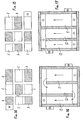
- the device is vertical and takes the form of a rectangular parallelepiped, in which successive layers of electrodes are arranged in successive parallel planes.
- an apparatus has a framework constituted by lateral faces such as a and end plates, such as b. Both have holes c.
- the apparatus is provided with chambers d for supplying the electrolyte, and at its upper part with chambers e collecting the solution obtained.
- electrode holders constituted, in the example treated, by flat plates f, provided with holes f 1 , and which can affect various configurations, for the reasons which will be explained below.
- these plates are housed g receiving the electrodes, both monopolar and bipolar.
- These housings generally rectangular or square, are also arranged in various configurations, depending on the arrangement provided for the electrodes of a "layer". Their dimensions correspond to that of the electrode they receive.
- Electrode holder plates are, as shown in fig. 1, spaced apart by means of intermediate pieces h, also pierced with holes h 1 , which coincide with those presented by the electrode holders and the end plates b.
- the electrode-carrying plates and the spacers are made of an insulating material and adapted to the particular operating conditions, such as temperature, aggressiveness of the solutions, etc.
- the housings have the same depth as the electrodes, generally between 1 and 3 mm if the electrodes are metallic, and between 4 and 5 mm if the electrodes are made of graphite for example.
- the intermediate pieces h preferably have a thickness of between 1.5 and 4 mm. These thicknesses depend on the operating conditions and the mechanical stability of the electrodes. The important thing is that, in the same device, all the housings have the same thickness; the same is true for the dividers.
- the width of the spacers is slightly greater than the spacing between two housings, for example 3 to 6 mm, and such that it allows, by superposition and clamping, to rigidly fix the electrodes in their housings and to hide their edges.
- these various elements are assembled and tightened on each other, like the filter plates of a filter press, by any system, for example by a screw-nut system, i.
- the spacers h are, as shown in fig. 6 and, in particular, FIGS. 11 to 13, of a length such that they determine an internal partitioning delimiting the chambers k (FIG. 11) which will be discussed below.
- the bipolar electrodes in any desired number are arranged "in a checkerboard pattern on an electrode holder, which thus constitutes a" layer of electrodes and in such a way that, once the apparatus is assembled, each part of a bipolar electrode one layer faces the bipolar part of opposite polarity of the electrode of the next layer.
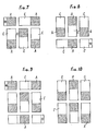
- FIGS. 7 and 8 represent, by way of nonlimiting examples, respectively the first and the second layers of bipolar electrodes, arranged "in a checkerboard pattern".
- Each layer consists of four bipolar electrodes C-A, having a cathode part C and an anode part A, and by a terminal electrode (A in FIG. 7, C in FIG. 8).
- the monopolar terminal electrodes of several successive layers are connected to a direct current source by the + and - poles.
- the succession of layers 1, 2, 1, 2, etc. shown in Figures 7 and 8 can also be reversed, i.e. 2, 1, 2, 1, etc.
- the number of layers can be even or odd with a minimum of two layers.
- the bipolar and monopolar electrodes of the extreme layers are electro-active only on the side of the surface facing the passage of the electrolyte.
- the bipolar and monopolar electrodes of the intermediate layers are active on both sides.
- FIGS. 9 and 10 show by way of example another possible arrangement with twelve elementary cells produced by means of superposed layers of a set of five bipolar electrodes (fig. 9) and a set of six bipolar electrodes (fig. 10).
- the electrolyser also has three electrolysis chambers, but each chamber has four cells, ie twelve elementary cells in total, which is the case of the device shown in FIG. 1.
- the anode ends (+) shown in FIG. 1 are joined together by connectors which are good conductors forming the pole (+) of the electrolyser. It is the same for the cathodes forming the pole (-).
- the device is provided at its lower part with an electrolyte distribution enclosure d and upper part of an enclosure and recovery of the solution produced.
- enclosures are connected, respectively, to the supply 14 of the electrolyte, and to the start 15 of the solution produced.
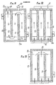
- FIGS. 11 to 13 represent, by way of example, three different couplings, by construction, of three chambers 11, 12, 13, FIG. 11 for example corresponding to an apparatus such as that shown in FIGS. 1 and 2.
- the internal arrangement of the apparatus is such that it determines a partitioning with baffles circulating the electrolyte, introduced at the base, of the upstream chamber 11 and distributed by a distribution device 11a, from this chamber 11 to the downstream chamber 13 passing through the intermediate chamber 12, the solution obtained being discharged at 13a.
- the pipes 20 for evacuating the hydrogen formed are advantageously provided with a gas-liquid separator 21.
- FIG. 12 represents an internal arrangement of the device according to which the electrolyte is distributed at the base of the device at 16 between the three chambers without communication between them, and exits at the upper part at 17.
- FIG. 13 represents an apparatus in which the electrolyte is also distributed between the chambers at its entry, but the solution obtained by electrolysis is collected in an enclosure 18 common to the chambers to be evacuated in 19.
- the chambers 11, 12 and 13 can be supplied individually with electrolytes of various natures. This embodiment can also be envisaged when the products of the electrolysis of the chamber 11 must be mixed with the products obtained by the electrolysis carried out in the chamber 12, etc.
- FIGS. 14 and 15 represent, by way of example, an electrolyser whose active unit surface of the electrodes of the chamber 11 is less than the active unit surface of the electrodes of the chamber 12 and that of the chamber 12 less than that of the room 13.
- FIGS. 16 and 17 represent, by way of example, possible hydraulic circuits in chambers corresponding to the cases of FIGS. 14 and 15.
- the chambers 13 then operate at a current density lower than that of the chambers 12, the latter operating at a current density lower than that of the chambers 11. It goes without saying that the chambers can occupy various positions in the electrolyser, in any order.
- the voltage across the pole (+) and pô) e (-) electrolyser is a function of the voltage per elementary cell multiplied by the number of cells.
- the current intensity is a function of the current density at which the electrolysis takes place multiplied by the sum of the anodic or cathodic active surfaces of the electrodes constituting a cell.
- the monopolar terminal electrodes, anode and cathode are located opposite and at the same level at the top or at the same level at the bottom of the electrolyser, or at different levels, anode at the top and cathode at the bottom, or vice versa.
- electrolysers can be mounted in hydraulic series or in parallel; the electrical mounting of several identical electrolysers is preferably carried out in series.
- the electrolysis device according to the invention has many advantages compared to known devices.
- edges of the bipolar electrodes being protected by the housings in which the electrodes are received, there is no leakage of current from one electrode to the next located in the same plane; in addition, the destruction of the electrode at these edges, usually covered with difficulty by a noble metal (platinum, iridium), is avoided, the edges not being exposed to the phenomenon of electrolysis.
- a noble metal platinum, iridium
- the present invention has the advantage to increase the overall yields of a complete installation because it allows on the one hand to improve the efficiency of the actual electrolysis by reducing the energy required at the terminals of the electrolyser, and on the other hand, to decrease losses of an electrotechnical nature, more particularly concerning losses by the Joule effect in bars, connections, cooling auxiliaries, etc.
- the voltage applied to the terminals of a cell is lower than that applied to known devices, because the checkerboard arrangement with spacers makes it possible to reduce the distance between the electrodes and consequently the resistance of the electrolyte . This gives better resistance of the electrodes over time and in particular of the voltage-sensitive anodes.
Landscapes
- Chemical & Material Sciences (AREA)
- Engineering & Computer Science (AREA)
- Chemical Kinetics & Catalysis (AREA)
- Electrochemistry (AREA)
- Materials Engineering (AREA)
- Metallurgy (AREA)
- Organic Chemistry (AREA)
- Electrolytic Production Of Non-Metals, Compounds, Apparatuses Therefor (AREA)
- Water Treatment By Electricity Or Magnetism (AREA)
Applications Claiming Priority (2)
| Application Number | Priority Date | Filing Date | Title |
|---|---|---|---|
| FR7927671A FR2469471A1 (fr) | 1979-11-09 | 1979-11-09 | Appareil d'electrolyse a electrodes bi-polaires notamment pour l'electrolyse de solutions salines avec obtention d'hypochlorite |
| FR7927671 | 1979-11-09 |
Publications (2)
| Publication Number | Publication Date |
|---|---|
| EP0029518A1 EP0029518A1 (fr) | 1981-06-03 |
| EP0029518B1 true EP0029518B1 (fr) | 1984-04-11 |
Family
ID=9231493
Family Applications (1)
| Application Number | Title | Priority Date | Filing Date |
|---|---|---|---|
| EP80106641A Expired EP0029518B1 (fr) | 1979-11-09 | 1980-10-29 | Appareil d'électrolyse à électrodes bipolaires, notamment pour l'électrolyse des solutions salines, avec obtention d'hypochlorite |
Country Status (4)
| Country | Link |
|---|---|
| US (1) | US4305806A (OSRAM) |
| EP (1) | EP0029518B1 (OSRAM) |
| DE (1) | DE3067464D1 (OSRAM) |
| FR (1) | FR2469471A1 (OSRAM) |
Families Citing this family (12)
| Publication number | Priority date | Publication date | Assignee | Title |
|---|---|---|---|---|
| US4382849A (en) * | 1980-12-11 | 1983-05-10 | Spicer Laurence E | Apparatus for electrolysis using gas and electrolyte channeling to reduce shunt currents |
| US4461692A (en) * | 1982-05-26 | 1984-07-24 | Ppg Industries, Inc. | Electrolytic cell |
| US4783246A (en) * | 1987-12-01 | 1988-11-08 | Eltech Systems Corporation | Bipolar rapid pass electrolytic hypochlorite generator |
| US6080290A (en) | 1997-01-03 | 2000-06-27 | Stuart Energy Systems Corporation | Mono-polar electrochemical system with a double electrode plate |
| RU2119555C1 (ru) * | 1997-11-18 | 1998-09-27 | Закрытое акционерное общество "Технохим-М" | Электрохимическое устройство |
| AU5908999A (en) * | 1998-09-02 | 2000-03-21 | Exceltec International Corporation | Electrolyzer |
| NZ590016A (en) * | 2010-12-17 | 2013-06-28 | Waikatolink Ltd | An electrolytic cell comprising at least two electrodes and at least one insulating layer with perforations |
| ITPD20130280A1 (it) * | 2013-10-09 | 2015-04-10 | Idropan Dell Orto Depuratori S R L | Apparecchiatura per il trattamento di un fluido |
| SG11202109344XA (en) * | 2019-05-15 | 2021-09-29 | Univ Nanyang Tech | Electrochemical system for low energy and high efficiency water desalination |
| CN112340815B (zh) * | 2019-08-06 | 2023-08-25 | 无锡小天鹅电器有限公司 | 电解组件、电解装置及衣物处理设备 |
| CN113548719B (zh) | 2019-08-06 | 2023-08-18 | 无锡小天鹅电器有限公司 | 电解组件及衣物处理设备 |
| CN116143247B (zh) * | 2023-03-22 | 2025-08-05 | 银海洁环保科技(北京)有限公司 | 电化学装置及处理系统 |
Family Cites Families (7)
| Publication number | Priority date | Publication date | Assignee | Title |
|---|---|---|---|---|
| US3119760A (en) * | 1959-12-30 | 1964-01-28 | Standard Oil Co | Electrolytic cell for the oxidation and reduction of organic compounds |
| GB1056889A (en) * | 1964-10-12 | 1967-02-01 | Albright & Wilson | Method and apparatus for performing electrolytic processes |
| GB1045816A (en) * | 1964-11-05 | 1966-10-19 | David J Evans Res Ltd | Improvements in or relating to electrodes for electrolytic cells |
| DE2362068A1 (de) * | 1973-05-03 | 1974-11-21 | Ppg Industries Inc | Elektrolytische zelle mit siliciumelektroden zur verwendung bei der elektrolyse von alkalichloriden |
| US3960699A (en) * | 1974-12-23 | 1976-06-01 | Basf Wyandotte Corporation | Self supporting electrodes for chlor-alkali cell |
| CA1074257A (en) * | 1976-04-01 | 1980-03-25 | Gow Enterprises Limited | Electrolytic system and novel electrolytic cells and reactors therefor |
| US4129494A (en) * | 1977-05-04 | 1978-12-12 | Norman Telfer E | Electrolytic cell for electrowinning of metals |
-
1979
- 1979-11-09 FR FR7927671A patent/FR2469471A1/fr active Granted
-
1980
- 1980-10-28 US US06/202,182 patent/US4305806A/en not_active Expired - Lifetime
- 1980-10-29 EP EP80106641A patent/EP0029518B1/fr not_active Expired
- 1980-10-29 DE DE8080106641T patent/DE3067464D1/de not_active Expired
Also Published As
| Publication number | Publication date |
|---|---|
| DE3067464D1 (en) | 1984-05-17 |
| FR2469471B1 (OSRAM) | 1983-01-28 |
| FR2469471A1 (fr) | 1981-05-22 |
| EP0029518A1 (fr) | 1981-06-03 |
| US4305806A (en) | 1981-12-15 |
Similar Documents
| Publication | Publication Date | Title |
|---|---|---|
| EP0029518B1 (fr) | Appareil d'électrolyse à électrodes bipolaires, notamment pour l'électrolyse des solutions salines, avec obtention d'hypochlorite | |
| JP6077087B2 (ja) | オゾン生成のための電解槽 | |
| CN100537849C (zh) | 用于电解槽的电极结构 | |
| CA1079222A (fr) | Type de cellule d'electrolyse pour la preparation industrielle du fluor | |
| FR2474534A1 (fr) | Appareil de production d'hypochlorite de sodium | |
| CH616961A5 (OSRAM) | ||
| JP2011517012A (ja) | 逆電気透析プロセスを実行するためのデバイス及び方法 | |
| FR2784979A1 (fr) | Procede electrochimique de desinfection des eaux par electroperoxydation et dispositif pour la mise en oeuvre d'un tel procede | |
| JP2016196672A (ja) | 電解槽および次亜塩素酸水製造装置 | |
| CA2515240A1 (fr) | Procede et dispositif de desinfection electrochimique des eaux | |
| FR2542763A1 (fr) | Procede et appareillage pour l'electrolyse d'une solution aqueuse diluee d'alcali caustique | |
| CA2249470C (fr) | Procede electrocatalytique de desoxygenation de l'eau de mer et dispositif pour sa mise en oeuvre | |
| EP0065889B1 (fr) | Appareil d'électrolyse à électrodes bipolaires notamment pour l'électrolyse de solutions salines | |
| FR2751637A1 (fr) | Cellule d'electrocoagulation pour le traitement d'effluents | |
| EP0010562A1 (fr) | Procédé d'électrolyse | |
| WO2008128302A1 (en) | Improved electrolytic cell | |
| SU831660A1 (ru) | Проточный гипохлоритный электролизер | |
| US4404082A (en) | Bipolar electrode for anodic processes in undivided cells | |
| KR20070088411A (ko) | 개선된 이온수 생성 장치 | |
| FR2689523A1 (fr) | Cellule bipolaire pour l'électrolyse en continu du chlorure de sodium. | |
| BE876070Q (fr) | Cellule electrolytique pour la production de composes oxyhalogenes. | |
| BE476141A (OSRAM) | ||
| FR2742450A1 (fr) | Procede pour la production d'hypochlorite | |
| CN113830865A (zh) | 降解水中文拉法辛的方法及电化学处理装置 | |
| EP0165357A1 (fr) | Cellule électrolytique pour le traitement d'effluents |
Legal Events
| Date | Code | Title | Description |
|---|---|---|---|
| PUAI | Public reference made under article 153(3) epc to a published international application that has entered the european phase |
Free format text: ORIGINAL CODE: 0009012 |
|
| AK | Designated contracting states |
Designated state(s): BE DE GB NL |
|
| 17P | Request for examination filed |
Effective date: 19810609 |
|
| DET | De: translation of patent claims | ||
| GRAA | (expected) grant |
Free format text: ORIGINAL CODE: 0009210 |
|
| AK | Designated contracting states |
Designated state(s): BE DE GB NL |
|
| REF | Corresponds to: |
Ref document number: 3067464 Country of ref document: DE Date of ref document: 19840517 |
|
| PGFP | Annual fee paid to national office [announced via postgrant information from national office to epo] |
Ref country code: BE Payment date: 19840930 Year of fee payment: 5 |
|
| PGFP | Annual fee paid to national office [announced via postgrant information from national office to epo] |
Ref country code: DE Payment date: 19841213 Year of fee payment: 5 |
|
| PLBE | No opposition filed within time limit |
Free format text: ORIGINAL CODE: 0009261 |
|
| STAA | Information on the status of an ep patent application or granted ep patent |
Free format text: STATUS: NO OPPOSITION FILED WITHIN TIME LIMIT |
|
| 26N | No opposition filed | ||
| PGFP | Annual fee paid to national office [announced via postgrant information from national office to epo] |
Ref country code: NL Payment date: 19871031 Year of fee payment: 8 |
|
| PG25 | Lapsed in a contracting state [announced via postgrant information from national office to epo] |
Ref country code: GB Effective date: 19881029 |
|
| PG25 | Lapsed in a contracting state [announced via postgrant information from national office to epo] |
Ref country code: BE Effective date: 19881031 |
|
| BERE | Be: lapsed |
Owner name: DEGREMONT Effective date: 19881031 |
|
| PG25 | Lapsed in a contracting state [announced via postgrant information from national office to epo] |
Ref country code: NL Effective date: 19890501 |
|
| NLV4 | Nl: lapsed or anulled due to non-payment of the annual fee | ||
| PG25 | Lapsed in a contracting state [announced via postgrant information from national office to epo] |
Ref country code: DE Effective date: 19890701 |
|
| GBPC | Gb: european patent ceased through non-payment of renewal fee |