EP0029518B1 - Electrolysis apparatus with bipolar electrodes, in particular for the electrolysis of brine to produce hypochlorite - Google Patents
Electrolysis apparatus with bipolar electrodes, in particular for the electrolysis of brine to produce hypochlorite Download PDFInfo
- Publication number
- EP0029518B1 EP0029518B1 EP80106641A EP80106641A EP0029518B1 EP 0029518 B1 EP0029518 B1 EP 0029518B1 EP 80106641 A EP80106641 A EP 80106641A EP 80106641 A EP80106641 A EP 80106641A EP 0029518 B1 EP0029518 B1 EP 0029518B1
- Authority
- EP
- European Patent Office
- Prior art keywords
- electrodes
- electrolysis
- chambers
- electrode
- bipolar electrodes
- Prior art date
- Legal status (The legal status is an assumption and is not a legal conclusion. Google has not performed a legal analysis and makes no representation as to the accuracy of the status listed.)
- Expired
Links
Images


Classifications
-
- C—CHEMISTRY; METALLURGY
- C25—ELECTROLYTIC OR ELECTROPHORETIC PROCESSES; APPARATUS THEREFOR
- C25B—ELECTROLYTIC OR ELECTROPHORETIC PROCESSES FOR THE PRODUCTION OF COMPOUNDS OR NON-METALS; APPARATUS THEREFOR
- C25B9/00—Cells or assemblies of cells; Constructional parts of cells; Assemblies of constructional parts, e.g. electrode-diaphragm assemblies; Process-related cell features
- C25B9/70—Assemblies comprising two or more cells
- C25B9/73—Assemblies comprising two or more cells of the filter-press type
- C25B9/75—Assemblies comprising two or more cells of the filter-press type having bipolar electrodes
-
- C—CHEMISTRY; METALLURGY
- C25—ELECTROLYTIC OR ELECTROPHORETIC PROCESSES; APPARATUS THEREFOR
- C25B—ELECTROLYTIC OR ELECTROPHORETIC PROCESSES FOR THE PRODUCTION OF COMPOUNDS OR NON-METALS; APPARATUS THEREFOR
- C25B11/00—Electrodes; Manufacture thereof not otherwise provided for
- C25B11/02—Electrodes; Manufacture thereof not otherwise provided for characterised by shape or form
- C25B11/036—Bipolar electrodes
Landscapes
- Chemical & Material Sciences (AREA)
- Engineering & Computer Science (AREA)
- Chemical Kinetics & Catalysis (AREA)
- Electrochemistry (AREA)
- Materials Engineering (AREA)
- Metallurgy (AREA)
- Organic Chemistry (AREA)
- Electrolytic Production Of Non-Metals, Compounds, Apparatuses Therefor (AREA)
- Water Treatment By Electricity Or Magnetism (AREA)
Description
La présente invention concerne un appareil d'électrolyse à électrodes bipolaires, utilisable pour réaliser des réactions électrochimiques, en particulier l'électrolyse d'une solution saline avec obtention d'une solution oxydante contenant des composés chlorés, principalement sous forme d'hypochlorite de sodium. Une telle solution ayant la même gamme d'utilisation qu'une solution d'hypochlorite de sodium du commerce, peut servir à la chloration des eaux de toute nature, y compris des eaux résiduaires, à un stade quelconque du traitement de ces eaux. Les composés oxydants présents dans une telle solution sont mesurés en « équivalents chlore actif • .The present invention relates to an electrolysis apparatus with bipolar electrodes, usable for carrying out electrochemical reactions, in particular the electrolysis of a saline solution with the production of an oxidizing solution containing chlorinated compounds, mainly in the form of sodium hypochlorite. . Such a solution having the same range of use as a commercial sodium hypochlorite solution, can be used for the chlorination of waters of all kinds, including waste waters, at any stage of the treatment of these waters. The oxidizing compounds present in such a solution are measured in "active chlorine equivalents".
Des électrolyseurs utilisant divers types d'assemblage d'électrodes bipolaires ont déjà été décrits et sont industriellement utilisés pour la réalisation de réactions électrochimiques diverses. C'est ainsi que le brevet US-A-3 410 784 décrit un appareil d'électrolyse dans lequel les électrodes sont réparties par rangées alternées, les unes constituées par des anodes, les autres par des cathodes, l'une des électrodes d'une rangée étant reliée à l'une des électrodes de l'autre rangée. Des nervures prévues dans le fond de l'électrolyseur supportent les rangées d'électrodes par l'intermédiaire d'éléments de séparation verticaux. Ces appareils connus, lorsqu'ils sont utilisés pour l'obtention d'une solution d'hypochlorite de sodium à partir d'un électrolyte à métaux alcalins tel que : eau de mer, eau saumâtre ou solution de chlorure de sodium, sont le siège de réactions d'oxydo-réduction électrolytique à proximité immédiate des électrodes et de réactions chimiques entre les électrodes.Electrolysers using various types of bipolar electrode assembly have already been described and are industrially used for carrying out various electrochemical reactions. US Pat. No. 3,410,784 describes an electrolysis apparatus in which the electrodes are distributed in alternating rows, some consisting of anodes, others consisting of cathodes, one of the electrodes one row being connected to one of the electrodes of the other row. Ribs provided in the bottom of the electrolyser support the rows of electrodes by means of vertical separating elements. These known devices, when used to obtain a sodium hypochlorite solution from an electrolyte with alkali metals such as: sea water, brackish water or sodium chloride solution, are the seat electrolytic redox reactions in the immediate vicinity of the electrodes and chemical reactions between the electrodes.
Le chlore actif présent dans la solution oxydante obtenue est dissocié et se trouve principalement sous forme d'acide hypochloreux et d'ions hypochlorites, en fonction entre autres du pH et de la température, avec une production simultanée d'hydrogène. Quand l'électrolyte est constitué par de l'eau de mer, la présence de sels de calcium et de magnésium donne lieu à la formation à la cathode d'un dépôt la rendant moins perméable au flux d'électrons et nécessitant périodiquement des lavages acides ou des inversions de courant de courte durée.The active chlorine present in the oxidizing solution obtained is dissociated and is mainly found in the form of hypochlorous acid and hypochlorite ions, depending, among other things, on pH and temperature, with simultaneous production of hydrogen. When the electrolyte is constituted by sea water, the presence of calcium and magnesium salts gives rise to the formation at the cathode of a deposit making it less permeable to the flow of electrons and requiring periodic acid washes or short-term current reversals.
Pour éviter ces inconvénients, il y a intérêt d'une part à limiter la concentration d'hydrogène formé, néfaste à la bonne tenue des électrodes, en l'éliminant au cours du traitement et, d'autre part, à opérer à des vitesses de circulation de l'électrolyte entre les électrodes relativement élevées de façon à diminuer les dépôts à la cathode et espacer ou éliminer les lavages ou les inversions de courant.To avoid these drawbacks, it is advantageous on the one hand to limit the concentration of hydrogen formed, detrimental to the good performance of the electrodes, by eliminating it during the treatment and, on the other hand, to operate at speeds circulation of the electrolyte between the relatively high electrodes so as to reduce deposits at the cathode and space or eliminate washes or current inversions.
Pour atteindre toutefois des taux de conversion élevés et donc augmenter la concentration en équivalent chlore actif de la solution obtenue, on peut augmenter la densité de courant ; si l'on veut obtenir des consommations spécifiques basses en kWh par kg d'équivalent chlore actif produit, il faut alors atteindre des tensions basses, ce qui peut être obtenu par une diminution de l'intervalle entre deux électrodes.However, in order to achieve high conversion rates and therefore increase the concentration of active chlorine equivalent in the solution obtained, the current density can be increased; if you want to obtain low specific consumption in kWh per kg of active chlorine equivalent produced, then you must reach low voltages, which can be obtained by reducing the interval between two electrodes.
Par ailleurs, au cours de l'électrolyse, la composition chimique de l'électrolyte se modifie, ce qui nécessite des conditions d'opération différentes, vitesse de l'électrolyte entre les électrodes, densité de courant,...Furthermore, during electrolysis, the chemical composition of the electrolyte changes, which requires different operating conditions, speed of the electrolyte between the electrodes, current density, etc.
Les perfectionnements apportés par l'invention permettent d'obtenir un rendement d'électrolyse bien supérieur au rendement habituel, donc de diminuer la consommation spécifique en kWh/kg d'équivalent chlore actif produit, autorisent d'opérer à des densités de courant différentes dans les différentes chambres de l'appareil et assurent un mélange efficace des composés à la sortie de ces chambres.The improvements brought about by the invention make it possible to obtain an electrolysis yield much higher than the usual yield, therefore to reduce the specific consumption in kWh / kg of active chlorine equivalent produced, allow to operate at different current densities in the various chambers of the apparatus and ensure an effective mixing of the compounds at the exit of these chambers.
L'invention concerne un appareil d'électrolyse à électrodes bipolaires, muni d'électrodes terminales monopolaires, comportant une pluralité de cellules électrolytiques élémentaires, formées chacune d'une succession d'électrodes bipolaires, disposées dans des portes-électrodes, enserrées entre deux plaques-supports extrêmes non conductrices, caractérisé en ce que chaque porte-électrodes comporte des logements recevant plusieurs électrodes bipolaires disposées en « damier de façon à ce que, dans la succession d'électrodes constituant une cellule électrolytique élémentaire, la partie anodique d'une électrode se trouve en regard de la partie cathodique de celle qui lui succède.The invention relates to an electrolysis apparatus with bipolar electrodes, provided with monopolar terminal electrodes, comprising a plurality of elementary electrolytic cells, each formed of a succession of bipolar electrodes, arranged in electrode holders, sandwiched between two plates. -extreme non-conductive supports, characterized in that each electrode holder comprises housings receiving several bipolar electrodes arranged in a "checkerboard fashion so that, in the succession of electrodes constituting an elementary electrolytic cell, the anodic part of an electrode is next to the cathode part of the one that follows it.
Les divers caractéristiques et avantages de l'invention ressortiront de la description, qui va suivre, de quelques-unes de ses formes possibles de réalisation, données à titre d'exemples non limitatifs.The various characteristics and advantages of the invention will emerge from the description, which will follow, of some of its possible embodiments, given by way of nonlimiting examples.
Au cours de cette description, on se réfère aux dessins ci-joints qui montrent :
- Figure 1 une vue en perspective éclatée d'un appareil suivant l'invention ;
- Figure 1a une vue en perspective d'une cel-Iule;
- Figure 2 une vue extérieure en perspective de l'appareil suivant la fig. 1 ;
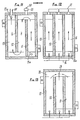
- Figures 3 à 6, des vues respectivement des plaques terminales (fig. 3), des porte-électrodes (fig. 4 et 5) et des pièces intercalaires ou d'espacement (fig. 6) ;
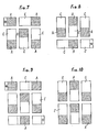
- Figures 7 à 10, des vues de « couches d'électrodes bipolaires suivant divers arrangements ;
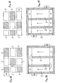
- Figures 11 à 13, des vues schématiques, dans un plan parallèle aux porte-électrodes des « chambres » créées dans l'appareil ;
- Figures 14 à 15, des vues de « couches d'électrodes bipolaires présentant des électrodes à surface inégale ;
- Figure 1 an exploded perspective view of an apparatus according to the invention;
- Figure 1a a perspective view of a cel-Iule;
- Figure 2 an external perspective view of the device according to fig. 1;
- Figures 3 to 6, views respectively of the end plates (fig. 3), the electrode holders (fig. 4 and 5) and spacers or spacers (fig. 6);
- Figures 7 to 10, views of "layers of bipolar electrodes according to various arrangements;
- Figures 11 to 13, schematic views, in a plane parallel to the electrode holders of the "chambers" created in the device;
- Figures 14 to 15, views of "bipolar electrode layers having electrodes with uneven surface;
Figures 16 et 17, des vues analogues aux fig. 11 à 13 des chambres correspondant aux cellules électrolytiques constituées par des couches successives d'électrodes bipolaires à surfaces acti-Figures 16 and 17, views similar to Figs. 11 to 13 of the chambers corresponding to the electrolytic cells constituted by successive layers of bipolar electrodes with active surfaces
ves inégales, telles que montrées aux fig. 14 et 15.uneven ves, as shown in figs. 14 and 15.
Dans l'exemple traité, l'appareil est vertical et affecte la forme d'un parallélépipède rectangle, dans lequel des couches successives d'électrodes sont disposées dans des plans successifs parallèles.In the example treated, the device is vertical and takes the form of a rectangular parallelepiped, in which successive layers of electrodes are arranged in successive parallel planes.
D'une façon générale, un appareil suivant l'invention présente une ossature constituée par des faces latérales telles que a et des plaques terminales, telles que b. Les unes et les autres sont percées de trous c.In general, an apparatus according to the invention has a framework constituted by lateral faces such as a and end plates, such as b. Both have holes c.
A sa partie inférieure, l'appareil est doté d'enceintes d d'amenée de l'électrolyte, et à sa partie supérieure d'enceintes e collectant la solution obtenue.At its lower part, the apparatus is provided with chambers d for supplying the electrolyte, and at its upper part with chambers e collecting the solution obtained.
Dans le boîtier ainsi formé, sont disposés des porte-électrodes constitués, dans l'exemple traité, par des plaques planes f, munies de trous f1, et qui peuvent affecter diverses configurations, pour les raisons que l'on exposera plus loin.In the housing thus formed, there are arranged electrode holders constituted, in the example treated, by flat plates f, provided with holes f 1 , and which can affect various configurations, for the reasons which will be explained below.
Dans ces plaques sont pratiqués des logements g recevant les électrodes, tant monopolaires que bipolaires. Ces logements, généralement de forme rectangulaire ou carrée, sont disposés également suivant diverses configurations, en fonction de l'arrangement prévu pour les électrodes d'une « couche ». Leurs dimensions correspondent à celle de l'électrode qu'ils reçoivent.In these plates are housed g receiving the electrodes, both monopolar and bipolar. These housings, generally rectangular or square, are also arranged in various configurations, depending on the arrangement provided for the electrodes of a "layer". Their dimensions correspond to that of the electrode they receive.
Ces plaques porte-électrodes sont, comme le montre la fig. 1, espacées entre elles au moyen de pièces intercalaires h, elles aussi percées de trous h1, qui coïncident avec ceux que présentent les porte-électrodes fet les plaques d'extrémité b.These electrode holder plates are, as shown in fig. 1, spaced apart by means of intermediate pieces h, also pierced with holes h 1 , which coincide with those presented by the electrode holders and the end plates b.
Les plaques porte-électrodes et les intercalaires sont en un matériau isolant et adapté aux conditions particulières d'opération, telles que température, aggressivité des solutions, etc. Les logements ont la même profondeur que les électrodes, généralement entre 1 et 3 mm si les électrodes sont métalliques, et entre 4 et 5 mm si les électrodes sont en graphite par exemple. Les pièces intercalaires h ont une épaisseur comprise de préférence entre 1,5 et 4 mm. Ces épaisseurs sont fonction des conditions d'opération et de la stabilité mécanique des électrodes. L'important est que, dans un même appareil, tous les logements aient la même épaisseur ; il en est de même pour les intercalaires.The electrode-carrying plates and the spacers are made of an insulating material and adapted to the particular operating conditions, such as temperature, aggressiveness of the solutions, etc. The housings have the same depth as the electrodes, generally between 1 and 3 mm if the electrodes are metallic, and between 4 and 5 mm if the electrodes are made of graphite for example. The intermediate pieces h preferably have a thickness of between 1.5 and 4 mm. These thicknesses depend on the operating conditions and the mechanical stability of the electrodes. The important thing is that, in the same device, all the housings have the same thickness; the same is true for the dividers.
La largeur des intercalaires est légèrement supérieure à l'espacement entre deux logements, par exemple 3 à 6 mm, et telle qu'elle permet, par superposition et serrage, de fixer rigidement les électrodes dans leurs logements et de masquer leurs arêtes.The width of the spacers is slightly greater than the spacing between two housings, for example 3 to 6 mm, and such that it allows, by superposition and clamping, to rigidly fix the electrodes in their housings and to hide their edges.
Au montage, ces divers éléments sont assemblés et serrés les uns sur les autres, à l'instar des plaques filtrantes d'un filtre-presse, au moyen d'un système quelconque, par exemple par un système vis-écrou, i.During assembly, these various elements are assembled and tightened on each other, like the filter plates of a filter press, by any system, for example by a screw-nut system, i.
Les intercalaires h sont, comme le montrent la fig. 6 et, notamment, les figures 11 à 13, d'une longueur telle qu'ils déterminent un cloisonnement interne délimitant les chambres k (fig. 11) dont il sera question plus loin.The spacers h are, as shown in fig. 6 and, in particular, FIGS. 11 to 13, of a length such that they determine an internal partitioning delimiting the chambers k (FIG. 11) which will be discussed below.
Les électrodes bipolaires en nombre quelconque voulu, sont disposées «en damier sur un porte-électrodes, qui constitue ainsi une « couche d'électrodes et de telle sorte que, une fois l'appareil monté, chaque partie d'une électrode bipolaire d'une couche fait face à la partie bipolaire de polarité opposée de l'électrode de la couche suivante.The bipolar electrodes in any desired number, are arranged "in a checkerboard pattern on an electrode holder, which thus constitutes a" layer of electrodes and in such a way that, once the apparatus is assembled, each part of a bipolar electrode one layer faces the bipolar part of opposite polarity of the electrode of the next layer.
Les figures 7 et 8 représentent, à titre d'exemples non limitatifs, respectivement la première et la deuxième couches d'électrodes bipolaires, disposées « en damier •. Chaque couche est constituée par quatre électrodes bipolaires C-A, présentant une partie cathodique C et une partie anodique A, et par une électrode terminale (A sur la figure 7, C sur la figure 8). Les électrodes terminales monopolaires de plusieurs couches successives sont reliées à une source de courant continu par les pôles + et -.FIGS. 7 and 8 represent, by way of nonlimiting examples, respectively the first and the second layers of bipolar electrodes, arranged "in a checkerboard pattern". Each layer consists of four bipolar electrodes C-A, having a cathode part C and an anode part A, and by a terminal electrode (A in FIG. 7, C in FIG. 8). The monopolar terminal electrodes of several successive layers are connected to a direct current source by the + and - poles.
Lorsque les couches successives d'électrodes bipolaires de la figure 7, puis de la figure 8, puis à nouveau de la figure 7, puis de la figure 8, et ainsi de suite, sont assemblées, on obtient successivement C en face de A, puis A en face de C, et ainsi de suite. Les anodes A et les cathodes C font face respectivement aux cathodes C et aux anodes A des couches qui leur succèdent.When the successive layers of bipolar electrodes in FIG. 7, then in FIG. 8, then again in FIG. 7, then in FIG. 8, and so on, are assembled, successively C is obtained opposite A, then A opposite C, and so on. The anodes A and the cathodes C face the cathodes C and the anodes A respectively of the successive layers.
La succession, dans un plan horizontal, de parties affrontées, de signe contraire, d'au moins deux couches d'électrodes bipolaires, constitue une cellule électrolytique élémentaire 10, représentée en perspective sur la fig. 1a. L'étagement dans le plan vertical, d'un certain nombre de cellules 10 ainsi constituées, forme, avec les pièces intercalaires et comme il a été décrit plus haut, des chambres d'électrolyse.The succession, in a horizontal plane, of facing parts, of opposite sign, of at least two layers of bipolar electrodes, constitutes an elementary
La succession des couches 1, 2, 1, 2, etc. représentée sur les figures 7 et 8 peut aussi bien être inversée, à savoir 2, 1, 2, 1, etc. Le nombre de couches peut être pair ou impair avec un minimum de deux couches.The succession of layers 1, 2, 1, 2, etc. shown in Figures 7 and 8 can also be reversed, i.e. 2, 1, 2, 1, etc. The number of layers can be even or odd with a minimum of two layers.
Les électrodes bipolaires et monopolaires des couches extrêmes sont électro-actives seulement du côté de la surface faisant face au passage de l'électrolyte.The bipolar and monopolar electrodes of the extreme layers are electro-active only on the side of the surface facing the passage of the electrolyte.
Les électrodes bipolaires et monopolaires des couches intermédiaires sont actives des deux côtés.The bipolar and monopolar electrodes of the intermediate layers are active on both sides.
Les figures 9 et 10 représentent à titre d'exemples un autre arrangement possible à douze cellules élémentaires réalisé au moyen de couches superposées d'un jeu de cinq électrodes bipolaires (fig. 9) et d'un jeu de six électrodes bipolaires (fig. 10). L'électrolyseur comporte dans ce cas également trois chambres d'électrolyse, mais chaque chambre comporte quatre cellules, soit douze cellules élémentaires au total, ce qui est le cas de l'appareil représenté à la figure 1.FIGS. 9 and 10 show by way of example another possible arrangement with twelve elementary cells produced by means of superposed layers of a set of five bipolar electrodes (fig. 9) and a set of six bipolar electrodes (fig. 10). In this case, the electrolyser also has three electrolysis chambers, but each chamber has four cells, ie twelve elementary cells in total, which is the case of the device shown in FIG. 1.
Les extrémités anodes (+) représentées sur la figure 1 sont réunies entre elles par des connecteurs bons conducteurs formant le pôle (+) de l'électrolyseur. Il en est de même pour les cathodes formant le pôle (-).The anode ends (+) shown in FIG. 1 are joined together by connectors which are good conductors forming the pole (+) of the electrolyser. It is the same for the cathodes forming the pole (-).
L'appareil est muni à sa partie inférieure d'une enceinte d de répartition de l'électrolyte et à sa partie supérieure d'une enceinte e de reprise de la solution produite.The device is provided at its lower part with an electrolyte distribution enclosure d and upper part of an enclosure and recovery of the solution produced.
Ces enceintes sont reliées, respectivement, à l'amenée 14 de l'électrolyte, et au départ 15 de la solution produite.These enclosures are connected, respectively, to the
Le cours suivi par l'électrolyte dans les chambres de l'appareil est différent suivant le couplage de ces chambres entre elles.The course followed by the electrolyte in the chambers of the apparatus is different depending on the coupling of these chambers with one another.
Les figures 11 à 13 représentent, à titre d'exemples, trois couplages différents, par construction, de trois chambres 11, 12, 13, la figure 11 par exemple correspondant à un appareil tel que celui représenté aux figures 1 et 2.FIGS. 11 to 13 represent, by way of example, three different couplings, by construction, of three
Dans l'exemple de la figure 11, l'arrangement interne de l'appareil est tel qu'il détermine un cloisonnement à chicanes faisant circuler l'électrolyte, introduit à la base, de la chambre amont 11 et réparti par un dispositif de répartition 11a, de cette chambre 11 à la chambre aval 13 en passant par la chambre intermédiaire 12, la solution obtenue étant évacuée en 13a. Les conduites 20 d'évacuation de l'hydrogène formé sont avantageusement munies d'un séparateur gaz-liquide 21.In the example of FIG. 11, the internal arrangement of the apparatus is such that it determines a partitioning with baffles circulating the electrolyte, introduced at the base, of the
La figure 12 représente une disposition interne de l'appareil suivant laquelle l'électrolyte est réparti à la base de l'appareil en 16 entre les trois chambres sans communication entre elles, et sort à la partie supérieure en 17.FIG. 12 represents an internal arrangement of the device according to which the electrolyte is distributed at the base of the device at 16 between the three chambers without communication between them, and exits at the upper part at 17.
La figure 13 représente un appareil dans lequel l'électrolyte est également réparti entre les chambres à son entrée, mais la solution obtenue par l'électrolyse est collectée dans une enceinte 18 commune aux chambres pour être évacuée en 19.FIG. 13 represents an apparatus in which the electrolyte is also distributed between the chambers at its entry, but the solution obtained by electrolysis is collected in an
Dans le cas des figures 12 et 13, les chambres 11, 12 et 13 peuvent être alimentées individuellement par des électrolytes de natures diverses. Cette forme de réalisation peut aussi être envisagée lorsque les produits de l'électrolyse de la chambre 11 doivent être mélangés avec les produits obtenus par l'électrolyse effectuée dans la chambre 12, etc.In the case of FIGS. 12 and 13, the
Jusqu'à présent, on a supposé que les surfaces actives des différentes électrodes étaient les mêmes ; elles peuvent cependant être différentes.Up to now, it has been assumed that the active surfaces of the different electrodes are the same; however, they may be different.
Les figures 14 et 15 représentent, à titre d'exemples, un électrolyseur dont la surface unitaire active des électrodes de la chambre 11 est inférieure à la surface unitaire active des électrodes de la chambre 12 et celle de la chambre 12 inférieure à celle de la chambre 13.FIGS. 14 and 15 represent, by way of example, an electrolyser whose active unit surface of the electrodes of the
Les figures 16 et 17 représentent à titre d'exemples des circuits hydrauliques possibles dans des chambres correspondant aux cas des figures 14 et 15.FIGS. 16 and 17 represent, by way of example, possible hydraulic circuits in chambers corresponding to the cases of FIGS. 14 and 15.
Les chambres 13 opèrent alors à une densité de courant inférieure à celle des chambres 12, ces dernières opérant à une densité de courant inférieure à celle des chambres 11. Il va de soi que les chambres peuvent occuper des positions diverses dans l'électrolyseur, dans un ordre quelconque.The
Le montage électrique interne des électrodes dans un même électrolyseur est en série parallèle.The internal electrical mounting of the electrodes in the same electrolyser is in parallel series.
La tension aux bornes de l'électrolyseur pôle (+) et pô)e (-) est fonction de la tension par cellule élémentaire multipliée par le nombre de cellules.The voltage across the pole (+) and pô) e (-) electrolyser is a function of the voltage per elementary cell multiplied by the number of cells.
L'intensité de courant est fonction de la densité de courant à laquelle s'opère l'électrolyse multipliée par la somme des surfaces actives anodiques ou cathodiques des électrodes constituant une cellule.The current intensity is a function of the current density at which the electrolysis takes place multiplied by the sum of the anodic or cathodic active surfaces of the electrodes constituting a cell.
Les électrodes terminales monopolaires, anode et cathode, se trouvent à l'opposé et au même niveau en haut ou au même niveau en bas de l'électrolyseur, ou à des niveaux différents, anode en haut et cathode en bas, ou inversement.The monopolar terminal electrodes, anode and cathode, are located opposite and at the same level at the top or at the same level at the bottom of the electrolyser, or at different levels, anode at the top and cathode at the bottom, or vice versa.
Plusieurs électrolyseurs peuvent être montés en série hydraulique ou en parallèle ; le montage électrique de plusieurs électrolyseurs identiques est réalisé de préférence en série.Several electrolysers can be mounted in hydraulic series or in parallel; the electrical mounting of several identical electrolysers is preferably carried out in series.
L'appareil d'électrolyse suivant l'invention présente de nombreux avantages par rapport aux appareils connus.The electrolysis device according to the invention has many advantages compared to known devices.
Les arêtes des électrodes bipolaires étant protégées par les logements dans lesquels sont reçues les électrodes, il ne se produit pas de fuite de courant d'une électrode à la suivante située dans le même plan ; en outre, la destruction de l'électrode au niveau de ces arêtes, habituellement recouvertes avec difficulté par un métal noble (platine, iridium), est évitée, les arêtes n'étant pas exposées au phénomène d'électrolyse.The edges of the bipolar electrodes being protected by the housings in which the electrodes are received, there is no leakage of current from one electrode to the next located in the same plane; in addition, the destruction of the electrode at these edges, usually covered with difficulty by a noble metal (platinum, iridium), is avoided, the edges not being exposed to the phenomenon of electrolysis.
La possibilité d'utiliser des équipements standards produits en série, ne nécessitant aucune soudure, facilite la fabrication et le montage d'un appareil suivant l'invention.The possibility of using standard equipment produced in series, requiring no welding, facilitates the manufacture and assembly of a device according to the invention.
En outre, si l'on veut accroître la production de l'appareil, on peut facilement ajouter des couches complémentaires d'électrodes identiques aux premières ou masquer un certain nombre de couches en atteignant cet accroissement par utilisation de plaques isolantes pleines à la place des couches d'électrodes.In addition, if we want to increase the production of the device, we can easily add additional layers of electrodes identical to the first or mask a number of layers by achieving this increase by using solid insulating plates instead of layers of electrodes.
Par ailleurs, la configuration de l'électrolyseur décrit permet d'utiliser des électrodes planes, et ceci :
- - quelle que soit la ou les matières utilisées à leur fabrication, à condition qu'elles soient conductrices de courant et adaptées aux conditions électrochimiques d'utilisation ;
- - quelle que soit leur épaisseur, les plaques porte-électrodes non conductrices de courant et adaptées aux conditions de l'électrolyse envisagée devant avoir la même épaisseur que les électrodes ;
- - quelle que soit la distance choisie entre deux couches successives, les intercalaires non conducteurs du courant et généralement de même matière que celle utilisée pour les logements devant être dimensionnés en conséquence ;
- - quel que soit le type d'électrodes choisi, c'est-à-dire surface pleine ou striée, etc., à condition qu'elle soit plane ;
- - quelle que soit la surface des électrodes à condition de respecter les indications énumérées ci-dessus.
- - whatever the material or materials used in their manufacture, provided that they are current-carrying and adapted to the electrochemical conditions of use;
- - whatever their thickness, the non-current-carrying electrode plates adapted to the conditions of the envisaged electrolysis must have the same thickness as the electrodes;
- - whatever the distance chosen between two successive layers, the non-conductive inserts of the current and generally of the same material as that used for the housings to be sized accordingly;
- - whatever the type of electrodes chosen, that is to say solid or striated surface, etc., provided that it is flat;
- - whatever the surface of the electrodes, provided that the indications listed above are observed.
De plus, la présente invention a pour avantage d'accroître les rendements globaux d'une installation complète car elle permet d'une part d'améliorer le rendement de l'électrolyse proprement dite en diminuant l'énergie nécessaire aux bornes de l'électrolyseur, et d'autre part, de diminuer les pertes de nature électrotechnique concernant plus particulièrement les pertes par effet Joule dans les barres, connexions, auxiliaires de refroidissement, etc.In addition, the present invention has the advantage to increase the overall yields of a complete installation because it allows on the one hand to improve the efficiency of the actual electrolysis by reducing the energy required at the terminals of the electrolyser, and on the other hand, to decrease losses of an electrotechnical nature, more particularly concerning losses by the Joule effect in bars, connections, cooling auxiliaries, etc.
Ceci est obtenu par l'utilisation d'électrodes bipolaires constituant des pluri-cellules nécessitant une intensité globale nettement inférieure à celle que nécessite un électrolyseur de surface active identique mais utilisant des monocellules.This is obtained by the use of bipolar electrodes constituting pluri-cells requiring an overall intensity significantly lower than that required by an electrolyzer of identical active surface but using monocells.
De même, la tension appliquée aux bornes d'une cellule est inférieure à celle appliquée aux appareils connus, car la disposition en damier avec pièces d'espacement permet de diminuer la distance entre les électrodes et par voie de conséquence la résistance de l'électrolyte. On obtient ainsi une meilleure tenue des électrodes dans le temps et en particulier des anodes sensibles au voltage.Similarly, the voltage applied to the terminals of a cell is lower than that applied to known devices, because the checkerboard arrangement with spacers makes it possible to reduce the distance between the electrodes and consequently the resistance of the electrolyte . This gives better resistance of the electrodes over time and in particular of the voltage-sensitive anodes.
Pour une même puissance consommée et en admettant les mêmes rendements, l'électrolyseur faisant l'objet de la présente invention a l'avantage d'opérer à une faible intensité globale et une plus forte tension aux bornes (V = v x nombre de cellules). Il en résulte un prix moindre pour les équipements transformateurs-redresseurs, le prix de ces derniers étant pour une même puissance inférieur lorsque 1 est plus faible et V plus élevé.For the same power consumed and assuming the same yields, the electrolyzer which is the subject of the present invention has the advantage of operating at a low overall intensity and a higher voltage at the terminals (V = vx number of cells) . This results in a lower price for transformer-rectifier equipment, the price of the latter being for the same power lower when 1 is lower and V higher.
Claims (9)
Applications Claiming Priority (2)
| Application Number | Priority Date | Filing Date | Title |
|---|---|---|---|
| FR7927671 | 1979-11-09 | ||
| FR7927671A FR2469471A1 (en) | 1979-11-09 | 1979-11-09 | ELECTROLYSIS APPARATUS WITH BI-POLAR ELECTRODES IN PARTICULAR FOR THE ELECTROLYSIS OF SALINE SOLUTIONS WITH OBTAINING HYPOCHLORITE |
Publications (2)
| Publication Number | Publication Date |
|---|---|
| EP0029518A1 EP0029518A1 (en) | 1981-06-03 |
| EP0029518B1 true EP0029518B1 (en) | 1984-04-11 |
Family
ID=9231493
Family Applications (1)
| Application Number | Title | Priority Date | Filing Date |
|---|---|---|---|
| EP80106641A Expired EP0029518B1 (en) | 1979-11-09 | 1980-10-29 | Electrolysis apparatus with bipolar electrodes, in particular for the electrolysis of brine to produce hypochlorite |
Country Status (4)
| Country | Link |
|---|---|
| US (1) | US4305806A (en) |
| EP (1) | EP0029518B1 (en) |
| DE (1) | DE3067464D1 (en) |
| FR (1) | FR2469471A1 (en) |
Families Citing this family (9)
| Publication number | Priority date | Publication date | Assignee | Title |
|---|---|---|---|---|
| US4382849A (en) * | 1980-12-11 | 1983-05-10 | Spicer Laurence E | Apparatus for electrolysis using gas and electrolyte channeling to reduce shunt currents |
| US4461692A (en) * | 1982-05-26 | 1984-07-24 | Ppg Industries, Inc. | Electrolytic cell |
| US4783246A (en) * | 1987-12-01 | 1988-11-08 | Eltech Systems Corporation | Bipolar rapid pass electrolytic hypochlorite generator |
| US6080290A (en) | 1997-01-03 | 2000-06-27 | Stuart Energy Systems Corporation | Mono-polar electrochemical system with a double electrode plate |
| CA2308197C (en) * | 1998-09-02 | 2009-06-30 | Exceltec International Corporation | Electrolyzer having divided fluid passageway |
| NZ590016A (en) * | 2010-12-17 | 2013-06-28 | Waikatolink Ltd | An electrolytic cell comprising at least two electrodes and at least one insulating layer with perforations |
| ITPD20130280A1 (en) * | 2013-10-09 | 2015-04-10 | Idropan Dell Orto Depuratori S R L | EQUIPMENT FOR THE TREATMENT OF A FLUID |
| SG11202109344XA (en) * | 2019-05-15 | 2021-09-29 | Univ Nanyang Tech | Electrochemical system for low energy and high efficiency water desalination |
| CN112340815B (en) * | 2019-08-06 | 2023-08-25 | 无锡小天鹅电器有限公司 | Electrolysis assembly, electrolysis device and clothes treatment equipment |
Family Cites Families (7)
| Publication number | Priority date | Publication date | Assignee | Title |
|---|---|---|---|---|
| US3119760A (en) * | 1959-12-30 | 1964-01-28 | Standard Oil Co | Electrolytic cell for the oxidation and reduction of organic compounds |
| GB1056889A (en) * | 1964-10-12 | 1967-02-01 | Albright & Wilson | Method and apparatus for performing electrolytic processes |
| GB1045816A (en) * | 1964-11-05 | 1966-10-19 | David J Evans Res Ltd | Improvements in or relating to electrodes for electrolytic cells |
| DE2362068A1 (en) * | 1973-05-03 | 1974-11-21 | Ppg Industries Inc | ELECTROLYTIC CELL WITH SILICON ELECTRODES FOR USE IN THE ELECTROLYSIS OF ALKALINE ICHLORIDES |
| US3960699A (en) * | 1974-12-23 | 1976-06-01 | Basf Wyandotte Corporation | Self supporting electrodes for chlor-alkali cell |
| CA1074257A (en) * | 1976-04-01 | 1980-03-25 | Gow Enterprises Limited | Electrolytic system and novel electrolytic cells and reactors therefor |
| US4129494A (en) * | 1977-05-04 | 1978-12-12 | Norman Telfer E | Electrolytic cell for electrowinning of metals |
-
1979
- 1979-11-09 FR FR7927671A patent/FR2469471A1/en active Granted
-
1980
- 1980-10-28 US US06/202,182 patent/US4305806A/en not_active Expired - Lifetime
- 1980-10-29 DE DE8080106641T patent/DE3067464D1/en not_active Expired
- 1980-10-29 EP EP80106641A patent/EP0029518B1/en not_active Expired
Also Published As
| Publication number | Publication date |
|---|---|
| EP0029518A1 (en) | 1981-06-03 |
| FR2469471A1 (en) | 1981-05-22 |
| DE3067464D1 (en) | 1984-05-17 |
| FR2469471B1 (en) | 1983-01-28 |
| US4305806A (en) | 1981-12-15 |
Similar Documents
| Publication | Publication Date | Title |
|---|---|---|
| JP6077087B2 (en) | Electrolyzer for ozone generation | |
| CN100537849C (en) | The electrode structure that is used for electrolyzer | |
| EP0029518B1 (en) | Electrolysis apparatus with bipolar electrodes, in particular for the electrolysis of brine to produce hypochlorite | |
| FR2474534A1 (en) | APPARATUS FOR PRODUCING SODIUM HYPOCHLORITE | |
| CH616961A5 (en) | ||
| FR2461021A1 (en) | ELECTROLYTIC CELL AND BIPOLAR ELECTROLYSER | |
| US20190270658A1 (en) | Advanced Oxidation System and Method In a UV Reactor with Electrode | |
| ES2299388B1 (en) | REACTOR FOR THE ELECTROCHEMICAL TREATMENT OF BIOMASS. | |
| FR2530027A1 (en) | POLARITY INVERSION ELECTRODES, IN PARTICULAR FOR ELECTRODIALYSIS OPERATIONS | |
| FR2784979A1 (en) | Long term electrochemical disinfection of water or waste water is effected by anodic oxidation combined with cathodic peroxidation | |
| CA2515240A1 (en) | Method and device for electrochemical disinfection of water | |
| JP6528173B2 (en) | Electrolytic cell and hypochlorous acid water production device | |
| CA2249470C (en) | Electrocatalytic method for the deoxygenating of sea water and device for its implementation | |
| FR2542763A1 (en) | METHOD AND APPARATUS FOR ELECTROLYSIS OF AQUEOUS SOLUTION DILUTED FROM CAUSTIC ALKALI | |
| EP0010562B1 (en) | Electrochemical process | |
| FR2751637A1 (en) | Detoxification of effluents by electro-coagulation | |
| EP0065889B1 (en) | Electrolysis apparatus with bipolar electrodes, especially useful in the electrolysis of brines | |
| RU2007132407A (en) | ELECTROLYZER FOR PRODUCING HYDROGEN AND OXYGEN BY ELECTROLYSIS OF AQUEOUS SOLUTION OF ELECTROLYTE | |
| FR2650304A1 (en) | METHOD FOR ELECTROLYTICALLY COATING A METAL SURFACE, AND ELECTROLYTIC CELL FOR ITS IMPLEMENTATION | |
| JPS6157396B2 (en) | ||
| SU831660A1 (en) | Flow-trhough hypochlorite electrolyser | |
| FR2585372A1 (en) | ELECTRODE FOR ELECTROLYSIS CELL | |
| FR2689523A1 (en) | Bipolar cell for continuous electrolysis of sodium chloride - has selective or permeable membanes to optimise desalination or hypochlorite prodn. | |
| CA1079684A (en) | Electrolyzer feeder | |
| FR2742450A1 (en) | Hypochlorite production |
Legal Events
| Date | Code | Title | Description |
|---|---|---|---|
| PUAI | Public reference made under article 153(3) epc to a published international application that has entered the european phase |
Free format text: ORIGINAL CODE: 0009012 |
|
| AK | Designated contracting states |
Designated state(s): BE DE GB NL |
|
| 17P | Request for examination filed |
Effective date: 19810609 |
|
| DET | De: translation of patent claims | ||
| GRAA | (expected) grant |
Free format text: ORIGINAL CODE: 0009210 |
|
| AK | Designated contracting states |
Designated state(s): BE DE GB NL |
|
| REF | Corresponds to: |
Ref document number: 3067464 Country of ref document: DE Date of ref document: 19840517 |
|
| PGFP | Annual fee paid to national office [announced via postgrant information from national office to epo] |
Ref country code: BE Payment date: 19840930 Year of fee payment: 5 |
|
| PGFP | Annual fee paid to national office [announced via postgrant information from national office to epo] |
Ref country code: DE Payment date: 19841213 Year of fee payment: 5 |
|
| PLBE | No opposition filed within time limit |
Free format text: ORIGINAL CODE: 0009261 |
|
| STAA | Information on the status of an ep patent application or granted ep patent |
Free format text: STATUS: NO OPPOSITION FILED WITHIN TIME LIMIT |
|
| 26N | No opposition filed | ||
| PGFP | Annual fee paid to national office [announced via postgrant information from national office to epo] |
Ref country code: NL Payment date: 19871031 Year of fee payment: 8 |
|
| PG25 | Lapsed in a contracting state [announced via postgrant information from national office to epo] |
Ref country code: GB Effective date: 19881029 |
|
| PG25 | Lapsed in a contracting state [announced via postgrant information from national office to epo] |
Ref country code: BE Effective date: 19881031 |
|
| BERE | Be: lapsed |
Owner name: DEGREMONT Effective date: 19881031 |
|
| PG25 | Lapsed in a contracting state [announced via postgrant information from national office to epo] |
Ref country code: NL Effective date: 19890501 |
|
| NLV4 | Nl: lapsed or anulled due to non-payment of the annual fee | ||
| PG25 | Lapsed in a contracting state [announced via postgrant information from national office to epo] |
Ref country code: DE Effective date: 19890701 |
|
| GBPC | Gb: european patent ceased through non-payment of renewal fee |