EP0027227A1 - Überdruckventil für eine hydraulische Anlage - Google Patents
Überdruckventil für eine hydraulische Anlage Download PDFInfo
- Publication number
- EP0027227A1 EP0027227A1 EP80106034A EP80106034A EP0027227A1 EP 0027227 A1 EP0027227 A1 EP 0027227A1 EP 80106034 A EP80106034 A EP 80106034A EP 80106034 A EP80106034 A EP 80106034A EP 0027227 A1 EP0027227 A1 EP 0027227A1
- Authority
- EP
- European Patent Office
- Prior art keywords
- valve
- seat
- hydraulic installation
- flexible enclosure
- pressure
- Prior art date
- Legal status (The legal status is an assumption and is not a legal conclusion. Google has not performed a legal analysis and makes no representation as to the accuracy of the status listed.)
- Granted
Links
Images

Classifications
-
- F—MECHANICAL ENGINEERING; LIGHTING; HEATING; WEAPONS; BLASTING
- F16—ENGINEERING ELEMENTS AND UNITS; GENERAL MEASURES FOR PRODUCING AND MAINTAINING EFFECTIVE FUNCTIONING OF MACHINES OR INSTALLATIONS; THERMAL INSULATION IN GENERAL
- F16K—VALVES; TAPS; COCKS; ACTUATING-FLOATS; DEVICES FOR VENTING OR AERATING
- F16K17/00—Safety valves; Equalising valves, e.g. pressure relief valves
- F16K17/02—Safety valves; Equalising valves, e.g. pressure relief valves opening on surplus pressure on one side; closing on insufficient pressure on one side
- F16K17/04—Safety valves; Equalising valves, e.g. pressure relief valves opening on surplus pressure on one side; closing on insufficient pressure on one side spring-loaded
- F16K17/0413—Safety valves; Equalising valves, e.g. pressure relief valves opening on surplus pressure on one side; closing on insufficient pressure on one side spring-loaded in the form of closure plates
-
- F—MECHANICAL ENGINEERING; LIGHTING; HEATING; WEAPONS; BLASTING
- F16—ENGINEERING ELEMENTS AND UNITS; GENERAL MEASURES FOR PRODUCING AND MAINTAINING EFFECTIVE FUNCTIONING OF MACHINES OR INSTALLATIONS; THERMAL INSULATION IN GENERAL
- F16K—VALVES; TAPS; COCKS; ACTUATING-FLOATS; DEVICES FOR VENTING OR AERATING
- F16K15/00—Check valves
- F16K15/02—Check valves with guided rigid valve members
-
- F—MECHANICAL ENGINEERING; LIGHTING; HEATING; WEAPONS; BLASTING
- F16—ENGINEERING ELEMENTS AND UNITS; GENERAL MEASURES FOR PRODUCING AND MAINTAINING EFFECTIVE FUNCTIONING OF MACHINES OR INSTALLATIONS; THERMAL INSULATION IN GENERAL
- F16K—VALVES; TAPS; COCKS; ACTUATING-FLOATS; DEVICES FOR VENTING OR AERATING
- F16K17/00—Safety valves; Equalising valves, e.g. pressure relief valves
- F16K17/02—Safety valves; Equalising valves, e.g. pressure relief valves opening on surplus pressure on one side; closing on insufficient pressure on one side
- F16K17/04—Safety valves; Equalising valves, e.g. pressure relief valves opening on surplus pressure on one side; closing on insufficient pressure on one side spring-loaded
- F16K17/0493—Safety valves; Equalising valves, e.g. pressure relief valves opening on surplus pressure on one side; closing on insufficient pressure on one side spring-loaded with a spring other than a helicoidal spring
-
- F—MECHANICAL ENGINEERING; LIGHTING; HEATING; WEAPONS; BLASTING
- F16—ENGINEERING ELEMENTS AND UNITS; GENERAL MEASURES FOR PRODUCING AND MAINTAINING EFFECTIVE FUNCTIONING OF MACHINES OR INSTALLATIONS; THERMAL INSULATION IN GENERAL
- F16K—VALVES; TAPS; COCKS; ACTUATING-FLOATS; DEVICES FOR VENTING OR AERATING
- F16K37/00—Special means in or on valves or other cut-off apparatus for indicating or recording operation thereof, or for enabling an alarm to be given
- F16K37/0008—Mechanical means
- F16K37/0016—Mechanical means having a graduated scale
-
- Y—GENERAL TAGGING OF NEW TECHNOLOGICAL DEVELOPMENTS; GENERAL TAGGING OF CROSS-SECTIONAL TECHNOLOGIES SPANNING OVER SEVERAL SECTIONS OF THE IPC; TECHNICAL SUBJECTS COVERED BY FORMER USPC CROSS-REFERENCE ART COLLECTIONS [XRACs] AND DIGESTS
- Y10—TECHNICAL SUBJECTS COVERED BY FORMER USPC
- Y10T—TECHNICAL SUBJECTS COVERED BY FORMER US CLASSIFICATION
- Y10T137/00—Fluid handling
- Y10T137/7722—Line condition change responsive valves
- Y10T137/7781—With separate connected fluid reactor surface
-
- Y—GENERAL TAGGING OF NEW TECHNOLOGICAL DEVELOPMENTS; GENERAL TAGGING OF CROSS-SECTIONAL TECHNOLOGIES SPANNING OVER SEVERAL SECTIONS OF THE IPC; TECHNICAL SUBJECTS COVERED BY FORMER USPC CROSS-REFERENCE ART COLLECTIONS [XRACs] AND DIGESTS
- Y10—TECHNICAL SUBJECTS COVERED BY FORMER USPC
- Y10T—TECHNICAL SUBJECTS COVERED BY FORMER US CLASSIFICATION
- Y10T137/00—Fluid handling
- Y10T137/7722—Line condition change responsive valves
- Y10T137/7837—Direct response valves [i.e., check valve type]
- Y10T137/7878—With bias adjustment indicator
-
- Y—GENERAL TAGGING OF NEW TECHNOLOGICAL DEVELOPMENTS; GENERAL TAGGING OF CROSS-SECTIONAL TECHNOLOGIES SPANNING OVER SEVERAL SECTIONS OF THE IPC; TECHNICAL SUBJECTS COVERED BY FORMER USPC CROSS-REFERENCE ART COLLECTIONS [XRACs] AND DIGESTS
- Y10—TECHNICAL SUBJECTS COVERED BY FORMER USPC
- Y10T—TECHNICAL SUBJECTS COVERED BY FORMER US CLASSIFICATION
- Y10T137/00—Fluid handling
- Y10T137/7722—Line condition change responsive valves
- Y10T137/7837—Direct response valves [i.e., check valve type]
- Y10T137/7904—Reciprocating valves
Definitions
- the invention relates to a relief valve for hydraulic installation, such as that used for the protection of installations against water hammer.
- the valve must include a compression spring setting device.
- the adjustment of such a device is particularly long and delicate. Indeed, on the one hand it is necessary to disassemble protective covers of the valve to access the adjustment device and, on the other hand, after calibration of the spring, the elimination of the tangential component of the 'force due to the spring implies an appropriate adjustment of the inclination of its antagonistic support flange disposed at the opposite end to the shutter member.
- the object of the invention is a particularly simple adjustment hydraulic discharge valve without requiring disassembly, and the operation of which is free of friction.
- the latter due to its constitution, tends to occupy a maximum volume for a minimum envelope surface, which also tends to replace the disc in its position parallel to the plane of the seat.
- the combination of the disc and the flexible enclosure therefore allows the shutter member to be perfectly stable on its jet, which makes it possible to dispense with mechanical guiding members which are still susceptible to friction or seizure.
- the flexible enclosure includes a valve for connecting to an inflation source and a pressure gauge outlet.
- the flexible enclosure is connected to a deformable expansion pocket placed in a reservoir placed, by means of an adjustable diaphragm, at the pressure prevailing in the hydraulic installation.
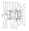
- the valve of FIG. 1 comprises a nozzle 1 having at its lower end a shoulder 2 and at its upper end a seat 3.
- the nozzle 1 is fixed through the circular opening 4 of a base plate 5 to the using a flange 6 by means of bolts not shown.
- the shoulder 2 is arranged in a circular groove 7 formed under the underside of the plate 5.
- the seat 3 cooperates with the underside of a valve 8 in the form of a disc 8 constituting the valve closure member.
- the disc 8 is surmounted by a central boss 9 disposed in a bore 11 of the lower flange 10 of a flexible enclosure 12 comprising an upper flange 13 fixed through an upper flange 14 using a half-flange 15 by means of bolts not shown.
- the upper flange 14 is itself fixed in an adjustable manner to the base plate 5 by peripheral tie rods 16 screwed on the lower plate 5 and on the upper flange 14.
- the flexible enclosure has at its upper part an axial duct 17 which crosses the flange 13 and the counter-flange 15 and which has at its upper end a valve 18 as well as a supply outlet 19 for a pressure gauge 20.
- the nozzle 1 being connected by means of the flange 6 to a hydraulic installation pipe not shown, the operation is as follows.
- the enclosure 12 After connecting the valve 18 to a pneumatic source (not shown), the enclosure 12 is inflated to a pressure whose value, controlled by the pressure gauge 20, is chosen as a function of that of the hydraulic pressure of the installation exerted in line with the seat 3 under the shutter member 8, and the inclination of the flange 14 is suitably adjusted by means of the fixing bolts on the tie rods 16.
- the closing plate 8 When an accidental excess pressure exceeding the setting value of the jack is induced in the hydraulic installation, the closing plate 8 is raised and lets around around the seat 3 a liquid blade which keeps it centered and is channeled by the skirt 23.
- the valve once adjusted has an operating threshold whose value is independent of the operating conditions of the hydraulic installation which it is called upon to protect.
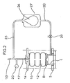
- FIG. 2 shows an application of this valve with an operating threshold which automatically follows the variations - of the operating conditions of the installation, insofar as these variations are not abrupt.
- a nozzle 25 connects the conduit 17 to a deformable pocket 26 which is placed in the enclosure of a sealed reservoir 27 connected via a conduit 28 to the pressure prevailing inside the nozzle 1 in communication with the hydraulic installation to be protected.
- an adjustable diaphragm 29 is arranged through the conduit 28.
- the operating threshold follows the slow variations in the operating pressure of the hydraulic installation, but not sudden variations such as those resulting from water hammer. It follows that the shutter member 8 only opens in the case of sudden overpressure.
- a nozzle 31 connects the conduit 17 through a diaphragm 32 to another flexible enclosure 33, which is subjected to the weight given by a setting load 34.
- the pressure prevailing in the enclosure 12 is thus imposed to remain equal in the long term to the constant pressure applied by the load 34, the presence of the diaphragm 32 nevertheless making it possible to control the valve by rapid variation of the pressure at 18.
Applications Claiming Priority (2)
| Application Number | Priority Date | Filing Date | Title |
|---|---|---|---|
| FR7925477A FR2467342A1 (fr) | 1979-10-12 | 1979-10-12 | Soupape de decharge d'une installation hydraulique |
| FR7925477 | 1979-10-12 |
Publications (2)
| Publication Number | Publication Date |
|---|---|
| EP0027227A1 true EP0027227A1 (de) | 1981-04-22 |
| EP0027227B1 EP0027227B1 (de) | 1985-05-15 |
Family
ID=9230642
Family Applications (1)
| Application Number | Title | Priority Date | Filing Date |
|---|---|---|---|
| EP80106034A Expired EP0027227B1 (de) | 1979-10-12 | 1980-10-06 | Überdruckventil für eine hydraulische Anlage |
Country Status (12)
| Country | Link |
|---|---|
| US (1) | US4412555A (de) |
| EP (1) | EP0027227B1 (de) |
| JP (1) | JPS5663166A (de) |
| AR (1) | AR224033A1 (de) |
| BR (1) | BR8006599A (de) |
| DE (1) | DE3070648D1 (de) |
| ES (1) | ES8106198A1 (de) |
| FR (1) | FR2467342A1 (de) |
| GR (1) | GR70763B (de) |
| MA (1) | MA18974A1 (de) |
| MX (1) | MX151345A (de) |
| PT (1) | PT71897B (de) |
Cited By (3)
| Publication number | Priority date | Publication date | Assignee | Title |
|---|---|---|---|---|
| FR2504974A1 (fr) * | 1981-04-30 | 1982-11-05 | Bennes Marrel | Valve hydraulique de coulissement pour verin de mine |
| US4620562A (en) * | 1982-09-28 | 1986-11-04 | Butterworth, Inc. | High pressure regulator valve |
| FR2648890A1 (fr) * | 1989-06-27 | 1990-12-28 | Labo Electronique Physique | Dispositif de protection contre une surpression |
Families Citing this family (1)
| Publication number | Priority date | Publication date | Assignee | Title |
|---|---|---|---|---|
| JPS60109976A (ja) * | 1983-11-18 | 1985-06-15 | Matsushita Electric Ind Co Ltd | テレビジョン受像機 |
Citations (4)
| Publication number | Priority date | Publication date | Assignee | Title |
|---|---|---|---|---|
| US2243711A (en) * | 1938-03-25 | 1941-05-27 | Lamb John | Automatically acting relief valve |
| DE1083096B (de) * | 1959-03-04 | 1960-06-09 | Eddelbuettel & Schneider | UEberdrucksicherung |
| FR1505971A (fr) * | 1966-01-17 | 1967-12-15 | Grove Valve & Regulator Co | Soupape de sûreté |
| FR2422889A1 (fr) * | 1978-04-14 | 1979-11-09 | Commissariat Energie Atomique | Soupape de regulation a declenchement automatique |
Family Cites Families (14)
| Publication number | Priority date | Publication date | Assignee | Title |
|---|---|---|---|---|
| DE460840C (de) * | 1928-06-06 | H C Alexander Bernhard Draeger | Einrichtung an Ventilen fuer Atmungsgeraete | |
| US886045A (en) * | 1906-03-06 | 1908-04-28 | Herman J Ehrlich | Valve. |
| US1631263A (en) * | 1924-04-09 | 1927-06-07 | Greenhouse Samuel | Pressure-operable valve |
| DE920771C (de) * | 1941-04-11 | 1954-11-29 | Messerschmitt Boelkow Blohm | Ventil, insbesondere fuer Kabinen von Hoehenflugzeugen |
| FR1021221A (fr) * | 1950-07-01 | 1953-02-16 | Neyrpic Ets | Appareil hydraulique pour le contrôle de la pression des liquides |
| DE1600818A1 (de) * | 1967-04-01 | 1970-04-23 | Hans Joergensen | Druckregelventil |
| US3636969A (en) * | 1970-02-17 | 1972-01-25 | Greer Hydraulics Inc | Relief and unloading valve |
| DE2103066C3 (de) * | 1971-01-22 | 1976-01-08 | Wacker-Chemitronic Gesellschaft Fuer Elektronik-Grundstoffe Mbh, 8263 Burghausen | Vorrichtung zur Herstellung von hochreinem Arsen |
| SU429215A1 (ru) * | 1972-04-17 | 1974-05-25 | А. С. Другое | Мембранный щелевой клапан |
| US3913615A (en) * | 1973-10-18 | 1975-10-21 | Pall Corp | Flat-lapped valve cartridge assembly with caged poppet |
| US3913613A (en) * | 1974-10-25 | 1975-10-21 | Boris Nikolaevich Kostjunin | Safety valve |
| CA1022425A (en) * | 1974-11-01 | 1977-12-13 | Singer Company (The) | Evaporator pressure regulator |
| US3933172A (en) * | 1975-02-24 | 1976-01-20 | Grove Valve And Regulator Company | Pipeline surge reliever with sanitary barrier |
| CA1074659A (en) * | 1978-02-28 | 1980-04-01 | Bengt A. Lindstrom | Pressure regulator |
-
1979
- 1979-10-12 FR FR7925477A patent/FR2467342A1/fr active Granted
-
1980
- 1980-10-06 EP EP80106034A patent/EP0027227B1/de not_active Expired
- 1980-10-06 DE DE8080106034T patent/DE3070648D1/de not_active Expired
- 1980-10-08 GR GR63086A patent/GR70763B/el unknown
- 1980-10-09 PT PT71897A patent/PT71897B/pt unknown
- 1980-10-09 JP JP14188380A patent/JPS5663166A/ja active Pending
- 1980-10-10 MA MA19173A patent/MA18974A1/fr unknown
- 1980-10-10 AR AR282843A patent/AR224033A1/es active
- 1980-10-10 MX MX184289A patent/MX151345A/es unknown
- 1980-10-10 ES ES495830A patent/ES8106198A1/es not_active Expired
- 1980-10-13 BR BR8006599A patent/BR8006599A/pt not_active IP Right Cessation
-
1982
- 1982-05-28 US US06/383,309 patent/US4412555A/en not_active Expired - Lifetime
Patent Citations (4)
| Publication number | Priority date | Publication date | Assignee | Title |
|---|---|---|---|---|
| US2243711A (en) * | 1938-03-25 | 1941-05-27 | Lamb John | Automatically acting relief valve |
| DE1083096B (de) * | 1959-03-04 | 1960-06-09 | Eddelbuettel & Schneider | UEberdrucksicherung |
| FR1505971A (fr) * | 1966-01-17 | 1967-12-15 | Grove Valve & Regulator Co | Soupape de sûreté |
| FR2422889A1 (fr) * | 1978-04-14 | 1979-11-09 | Commissariat Energie Atomique | Soupape de regulation a declenchement automatique |
Cited By (4)
| Publication number | Priority date | Publication date | Assignee | Title |
|---|---|---|---|---|
| FR2504974A1 (fr) * | 1981-04-30 | 1982-11-05 | Bennes Marrel | Valve hydraulique de coulissement pour verin de mine |
| US4620562A (en) * | 1982-09-28 | 1986-11-04 | Butterworth, Inc. | High pressure regulator valve |
| FR2648890A1 (fr) * | 1989-06-27 | 1990-12-28 | Labo Electronique Physique | Dispositif de protection contre une surpression |
| EP0405684A1 (de) * | 1989-06-27 | 1991-01-02 | Laboratoires D'electronique Philips | Sicherheitsvorrichtung gegen einen Überdruck |
Also Published As
| Publication number | Publication date |
|---|---|
| GR70763B (de) | 1983-03-16 |
| AR224033A1 (es) | 1981-10-15 |
| JPS5663166A (en) | 1981-05-29 |
| DE3070648D1 (en) | 1985-06-20 |
| BR8006599A (pt) | 1981-04-22 |
| PT71897B (fr) | 1981-08-31 |
| MA18974A1 (fr) | 1981-07-01 |
| ES495830A0 (es) | 1981-07-16 |
| PT71897A (fr) | 1980-11-01 |
| FR2467342A1 (fr) | 1981-04-17 |
| EP0027227B1 (de) | 1985-05-15 |
| ES8106198A1 (es) | 1981-07-16 |
| FR2467342B1 (de) | 1983-03-11 |
| MX151345A (es) | 1984-11-12 |
| US4412555A (en) | 1983-11-01 |
Similar Documents
| Publication | Publication Date | Title |
|---|---|---|
| EP0032346B1 (de) | Mit einer hydraulischen Bremse versehenes Sicherheitsventil | |
| EP0415991B1 (de) | Automatische füllbegrenzungsvorrichtung für behälter | |
| EP0037334B1 (de) | Absperrventilvorrichtung mit Überdrucksicherung | |
| FR2471873A1 (fr) | Dispositif de suspension de la caisse d'un vehicule permettant de regler la hauteur de ce vehicule au-dessus du sol par de faibles variations de la pression d'huile | |
| FR2568974A1 (fr) | Dispositif d'assistance pour soupape de surete | |
| FR2582764A1 (fr) | Ressort pneumatique | |
| EP0027227A1 (de) | Überdruckventil für eine hydraulische Anlage | |
| FR2839163A1 (fr) | Regulateur de pression notamment pour un systeme d'alimentation en carburant | |
| FR3013098A1 (fr) | Dispositif de limitation de la surpression | |
| EP0237456A1 (de) | Hydraulischer Schwingungsunterdrücker und dessen Anwendung an Ventilen und dergleichen | |
| EP0116247B1 (de) | Sicherheitsventil mit integrierter Pilotsteuerung | |
| FR2619884A1 (fr) | Soupape de securite pilotee | |
| FR2528517A1 (fr) | Obturateur destine a etre monte dans un corps | |
| EP0516528B1 (de) | Sicherheitsventil für den Entlüftungskreislauf eines Kfz-Kraftstoffbehälters | |
| FR2681386A1 (fr) | Bloc hydropneumatique muni d'un accumulateur hydropneumatique a membrane et d'un amortisseur dissymetrique. | |
| FR2476790A1 (fr) | Limiteur de remplissage pour cuves de stockage de fluide | |
| FR2481404A1 (fr) | Robinet sanitaire comportant un organe de marche-arret a deux positions stables | |
| EP1783575B1 (de) | Druckminderungsvorrichtung zur automatischen Regulierung des Nachdrucks eines gasförmigen Fluids | |
| FR2500579A1 (fr) | Purgeur automatique d'air pour conduite d'eau en charge | |
| FR2563888A1 (fr) | Systeme de clapet antiretour ultra-rapide pour transducteurs de pression et similaires | |
| FR2891633A1 (fr) | Dispositif formant detendeur de gaz | |
| BE468691A (de) | ||
| FR2486619A1 (fr) | Perfectionnement aux valves de gonflage et de degonglage d'enveloppes pneumatiques, notamment de bateaux | |
| EP0410837A1 (de) | Ventil zur Tankentleerung, insbesondere für Wärmeschutztanks | |
| BE467646A (de) |
Legal Events
| Date | Code | Title | Description |
|---|---|---|---|
| PUAI | Public reference made under article 153(3) epc to a published international application that has entered the european phase |
Free format text: ORIGINAL CODE: 0009012 |
|
| AK | Designated contracting states |
Designated state(s): BE DE FR GB IT NL |
|
| 17P | Request for examination filed |
Effective date: 19810928 |
|
| ITF | It: translation for a ep patent filed |
Owner name: JACOBACCI & PERANI S.P.A. |
|
| GRAA | (expected) grant |
Free format text: ORIGINAL CODE: 0009210 |
|
| AK | Designated contracting states |
Designated state(s): BE DE FR GB IT NL |
|
| REF | Corresponds to: |
Ref document number: 3070648 Country of ref document: DE Date of ref document: 19850620 |
|
| PLBE | No opposition filed within time limit |
Free format text: ORIGINAL CODE: 0009261 |
|
| STAA | Information on the status of an ep patent application or granted ep patent |
Free format text: STATUS: NO OPPOSITION FILED WITHIN TIME LIMIT |
|
| 26N | No opposition filed | ||
| PGFP | Annual fee paid to national office [announced via postgrant information from national office to epo] |
Ref country code: GB Payment date: 19920821 Year of fee payment: 13 |
|
| PGFP | Annual fee paid to national office [announced via postgrant information from national office to epo] |
Ref country code: BE Payment date: 19921001 Year of fee payment: 13 |
|
| PGFP | Annual fee paid to national office [announced via postgrant information from national office to epo] |
Ref country code: DE Payment date: 19921016 Year of fee payment: 13 |
|
| ITTA | It: last paid annual fee | ||
| PGFP | Annual fee paid to national office [announced via postgrant information from national office to epo] |
Ref country code: NL Payment date: 19921031 Year of fee payment: 13 |
|
| PG25 | Lapsed in a contracting state [announced via postgrant information from national office to epo] |
Ref country code: GB Effective date: 19931006 |
|
| PG25 | Lapsed in a contracting state [announced via postgrant information from national office to epo] |
Ref country code: BE Effective date: 19931031 |
|
| BERE | Be: lapsed |
Owner name: ALSTHOM-ATLANTIQUE Effective date: 19931031 |
|
| PG25 | Lapsed in a contracting state [announced via postgrant information from national office to epo] |
Ref country code: NL Effective date: 19940501 |
|
| GBPC | Gb: european patent ceased through non-payment of renewal fee |
Effective date: 19931006 |
|
| NLV4 | Nl: lapsed or anulled due to non-payment of the annual fee | ||
| PG25 | Lapsed in a contracting state [announced via postgrant information from national office to epo] |
Ref country code: DE Effective date: 19940701 |
|
| PGFP | Annual fee paid to national office [announced via postgrant information from national office to epo] |
Ref country code: FR Payment date: 19980923 Year of fee payment: 19 |
|
| PG25 | Lapsed in a contracting state [announced via postgrant information from national office to epo] |
Ref country code: FR Free format text: LAPSE BECAUSE OF NON-PAYMENT OF DUE FEES Effective date: 20000630 |
|
| REG | Reference to a national code |
Ref country code: FR Ref legal event code: ST |