EP0027227A1 - Relief valve for a hydraulic installation - Google Patents
Relief valve for a hydraulic installation Download PDFInfo
- Publication number
- EP0027227A1 EP0027227A1 EP80106034A EP80106034A EP0027227A1 EP 0027227 A1 EP0027227 A1 EP 0027227A1 EP 80106034 A EP80106034 A EP 80106034A EP 80106034 A EP80106034 A EP 80106034A EP 0027227 A1 EP0027227 A1 EP 0027227A1
- Authority
- EP
- European Patent Office
- Prior art keywords
- valve
- seat
- hydraulic installation
- flexible enclosure
- pressure
- Prior art date
- Legal status (The legal status is an assumption and is not a legal conclusion. Google has not performed a legal analysis and makes no representation as to the accuracy of the status listed.)
- Granted
Links
Images

Classifications
-
- F—MECHANICAL ENGINEERING; LIGHTING; HEATING; WEAPONS; BLASTING
- F16—ENGINEERING ELEMENTS AND UNITS; GENERAL MEASURES FOR PRODUCING AND MAINTAINING EFFECTIVE FUNCTIONING OF MACHINES OR INSTALLATIONS; THERMAL INSULATION IN GENERAL
- F16K—VALVES; TAPS; COCKS; ACTUATING-FLOATS; DEVICES FOR VENTING OR AERATING
- F16K17/00—Safety valves; Equalising valves, e.g. pressure relief valves
- F16K17/02—Safety valves; Equalising valves, e.g. pressure relief valves opening on surplus pressure on one side; closing on insufficient pressure on one side
- F16K17/04—Safety valves; Equalising valves, e.g. pressure relief valves opening on surplus pressure on one side; closing on insufficient pressure on one side spring-loaded
- F16K17/0413—Safety valves; Equalising valves, e.g. pressure relief valves opening on surplus pressure on one side; closing on insufficient pressure on one side spring-loaded in the form of closure plates
-
- F—MECHANICAL ENGINEERING; LIGHTING; HEATING; WEAPONS; BLASTING
- F16—ENGINEERING ELEMENTS AND UNITS; GENERAL MEASURES FOR PRODUCING AND MAINTAINING EFFECTIVE FUNCTIONING OF MACHINES OR INSTALLATIONS; THERMAL INSULATION IN GENERAL
- F16K—VALVES; TAPS; COCKS; ACTUATING-FLOATS; DEVICES FOR VENTING OR AERATING
- F16K15/00—Check valves
- F16K15/02—Check valves with guided rigid valve members
-
- F—MECHANICAL ENGINEERING; LIGHTING; HEATING; WEAPONS; BLASTING
- F16—ENGINEERING ELEMENTS AND UNITS; GENERAL MEASURES FOR PRODUCING AND MAINTAINING EFFECTIVE FUNCTIONING OF MACHINES OR INSTALLATIONS; THERMAL INSULATION IN GENERAL
- F16K—VALVES; TAPS; COCKS; ACTUATING-FLOATS; DEVICES FOR VENTING OR AERATING
- F16K17/00—Safety valves; Equalising valves, e.g. pressure relief valves
- F16K17/02—Safety valves; Equalising valves, e.g. pressure relief valves opening on surplus pressure on one side; closing on insufficient pressure on one side
- F16K17/04—Safety valves; Equalising valves, e.g. pressure relief valves opening on surplus pressure on one side; closing on insufficient pressure on one side spring-loaded
- F16K17/0493—Safety valves; Equalising valves, e.g. pressure relief valves opening on surplus pressure on one side; closing on insufficient pressure on one side spring-loaded with a spring other than a helicoidal spring
-
- F—MECHANICAL ENGINEERING; LIGHTING; HEATING; WEAPONS; BLASTING
- F16—ENGINEERING ELEMENTS AND UNITS; GENERAL MEASURES FOR PRODUCING AND MAINTAINING EFFECTIVE FUNCTIONING OF MACHINES OR INSTALLATIONS; THERMAL INSULATION IN GENERAL
- F16K—VALVES; TAPS; COCKS; ACTUATING-FLOATS; DEVICES FOR VENTING OR AERATING
- F16K37/00—Special means in or on valves or other cut-off apparatus for indicating or recording operation thereof, or for enabling an alarm to be given
- F16K37/0008—Mechanical means
- F16K37/0016—Mechanical means having a graduated scale
-
- Y—GENERAL TAGGING OF NEW TECHNOLOGICAL DEVELOPMENTS; GENERAL TAGGING OF CROSS-SECTIONAL TECHNOLOGIES SPANNING OVER SEVERAL SECTIONS OF THE IPC; TECHNICAL SUBJECTS COVERED BY FORMER USPC CROSS-REFERENCE ART COLLECTIONS [XRACs] AND DIGESTS
- Y10—TECHNICAL SUBJECTS COVERED BY FORMER USPC
- Y10T—TECHNICAL SUBJECTS COVERED BY FORMER US CLASSIFICATION
- Y10T137/00—Fluid handling
- Y10T137/7722—Line condition change responsive valves
- Y10T137/7781—With separate connected fluid reactor surface
-
- Y—GENERAL TAGGING OF NEW TECHNOLOGICAL DEVELOPMENTS; GENERAL TAGGING OF CROSS-SECTIONAL TECHNOLOGIES SPANNING OVER SEVERAL SECTIONS OF THE IPC; TECHNICAL SUBJECTS COVERED BY FORMER USPC CROSS-REFERENCE ART COLLECTIONS [XRACs] AND DIGESTS
- Y10—TECHNICAL SUBJECTS COVERED BY FORMER USPC
- Y10T—TECHNICAL SUBJECTS COVERED BY FORMER US CLASSIFICATION
- Y10T137/00—Fluid handling
- Y10T137/7722—Line condition change responsive valves
- Y10T137/7837—Direct response valves [i.e., check valve type]
- Y10T137/7878—With bias adjustment indicator
-
- Y—GENERAL TAGGING OF NEW TECHNOLOGICAL DEVELOPMENTS; GENERAL TAGGING OF CROSS-SECTIONAL TECHNOLOGIES SPANNING OVER SEVERAL SECTIONS OF THE IPC; TECHNICAL SUBJECTS COVERED BY FORMER USPC CROSS-REFERENCE ART COLLECTIONS [XRACs] AND DIGESTS
- Y10—TECHNICAL SUBJECTS COVERED BY FORMER USPC
- Y10T—TECHNICAL SUBJECTS COVERED BY FORMER US CLASSIFICATION
- Y10T137/00—Fluid handling
- Y10T137/7722—Line condition change responsive valves
- Y10T137/7837—Direct response valves [i.e., check valve type]
- Y10T137/7904—Reciprocating valves
Landscapes
- Engineering & Computer Science (AREA)
- General Engineering & Computer Science (AREA)
- Mechanical Engineering (AREA)
- Safety Valves (AREA)
- Details Of Valves (AREA)
Abstract
La soupape comporte un clapet circulaire (8) soumis d'un côté à l'action d'un organe de poussée réglable et appliqué de l'autre côté contre un siège (3) relié à la pression de l'installation hydraulique, l'organe de poussée (12) étant constitué par une enceinte souple (12). La soupape est notamment utilisée dans la protection des installations hydrauliques contre les surpressions accidentelles.The valve comprises a circular valve (8) subjected on one side to the action of an adjustable thrust member and applied on the other side against a seat (3) connected to the pressure of the hydraulic installation, the thrust member (12) being constituted by a flexible enclosure (12). The valve is notably used in the protection of hydraulic installations against accidental overpressures.
Description
L'invention est relative à une soupape de décharge pour installation hydraulique, telle que celle utilisée pour la protection des installations contre les coups de bélier.The invention relates to a relief valve for hydraulic installation, such as that used for the protection of installations against water hammer.
Une telle soupape, qui comporte un organe d'obturation appliqué contre un siège par un ressort de compression, a été décrite notamment dans le brevet français n° 1 021 221.Such a valve, which comprises a closure member applied against a seat by a compression spring, has been described in particular in French patent No. 1,021,221.
Mais pour pouvoir être adaptée aux conditions locales d'exploitation, la soupape doit comporter un dispositif de tarage du ressort de compression. Or le réglage d'un tel dispositif est particulièrement long et délicat. En effet, d'une part il y a lieu de procéder à des démontages de capots de protection de la soupape pour accéder au dispositif de réglage et, d'autre part, après tarage du ressort, l'élimination de la composante tangentielle de l'effort dû au ressort implique un réglage approprié de l'inclinaison de sa bride antagoniste d'appui disposée à l'extrémité opposée à l'organe d'obturation.But to be able to be adapted to the local operating conditions, the valve must include a compression spring setting device. However, the adjustment of such a device is particularly long and delicate. Indeed, on the one hand it is necessary to disassemble protective covers of the valve to access the adjustment device and, on the other hand, after calibration of the spring, the elimination of the tangential component of the 'force due to the spring implies an appropriate adjustment of the inclination of its antagonistic support flange disposed at the opposite end to the shutter member.
D'autres soupapes connues, par exemple par le brevet américain n° 2 243 711 (Lamb) comportent une commande hydraulique par vérin à piston. Le frottement des joints d'un tel piston sur la paroi du cylindre crée des risques de perte d'étanchéité et de blocage mécanique.Other known valves, for example by US Patent No. 2,243,711 (Lamb) include hydraulic control by piston cylinder. The friction of the seals of such a piston on the cylinder wall creates the risk of loss of tightness and mechanical blockage.
L'invention a pour but une soupape de décharge hydraulique de réglage particulièrement simple sans nécessiter de démontage, et dont le fonctionnement soit exempt de frottement.The object of the invention is a particularly simple adjustment hydraulic discharge valve without requiring disassembly, and the operation of which is free of friction.
L'invention a pour objet une soupape de décharge pour installation hydraulique, cette soupape comportant
- - un clapet coopérant avec un siège circulaire, la face de ce clapet appliquée sur ce siège subissant la pression de l'installation hydraulique
- - et un organe de poussée pour maintenir ce clapet appliqué sur ce siège,
- - caractérisée par le fait que cet organe de poussée est constitué par une enceinte souple de forme sensiblement cylindrique dont la longueur augmente en présence d'une surpression interne,
- - le clapet présentant la forme d'un disque circulaire d'un diamètre au moins égal à 1,20 fois et de préférence sensiblement égal à 1,25 fois celui de l'ouverture du siège.
- - a valve cooperating with a circular seat, the face of this valve applied to this seat undergoing pressure from the hydraulic installation
- - and a thrust member to maintain this valve applied to this seat,
- - characterized in that this thrust member is constituted by a flexible enclosure of substantially cylindrical shape whose length increases in the presence of an internal overpressure,
- - The valve having the shape of a circular disc with a diameter at least equal to 1.20 times and preferably substantially equal to 1.25 times that of the opening of the seat.
Un tel disque est soumis :
- - d'une part à des efforts hydrauliques qui tendent à le replacer dans sa position parallèle au plan du siège, chaque fois que la réaction d'appui du disque s'exerce sur la face opposée au jet.
- - d'autre part à des forces de réaction dues à l'enceinte souple.
- - On the one hand to hydraulic forces which tend to return it to its position parallel to the plane of the seat, each time the bearing reaction of the disc is exerted on the face opposite to the jet.
- - on the other hand to reaction forces due to the flexible enclosure.
Cette dernière, de part sa constitution, a tendance à occuper un volume maximal pour une surface d'enveloppe minimal, ce qui tend également à replacer le disque dans sa position parallèle au plan du siège.The latter, due to its constitution, tends to occupy a maximum volume for a minimum envelope surface, which also tends to replace the disc in its position parallel to the plane of the seat.
La combinaison du disque et de l'enceinte souple permet donc à l'organe d'obturation d'être parfaitement stable sur son jet, ce qui permet de se passer d'organes mécaniques de guidage toujours susceptibles de frottements ou de grippage.The combination of the disc and the flexible enclosure therefore allows the shutter member to be perfectly stable on its jet, which makes it possible to dispense with mechanical guiding members which are still susceptible to friction or seizure.
Dans une réalisation avantageuse de l'invention, l'enceinte souple comporte une valve de liaison à une source de gonflage et une prise de manomètre de contrôle.In an advantageous embodiment of the invention, the flexible enclosure includes a valve for connecting to an inflation source and a pressure gauge outlet.
Dans une application particulière de la soupape selon l'invention l'enceinte souple est reliée à une poche d'expansion déformable placée dans un réservoir placé, par l'intermédiaire d'un diaphragme réglable, à la pression régnant dans l'installation hydraulique.In a particular application of the valve according to the invention, the flexible enclosure is connected to a deformable expansion pocket placed in a reservoir placed, by means of an adjustable diaphragm, at the pressure prevailing in the hydraulic installation.
Dans une autre application, l'enceinte souple est reliée à une autre enceinte souple soumise au poids d'une charge de tarage. Les caractéristiques et avantages de l'invention ressortiront de la description de divers modes de réalisation donnés à titre d'illustration dans les dessins annexés.
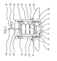
- La figure 1 est une vue en coupe axiale d'une soupape selon l'invention.
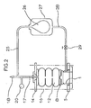
- La figure 2 est une vue schématique en coupe de cette soupape dans une application particulière.
- La figure 3 est une vue schématique en coupe de cette soupape dans une autre application.
- Figure 1 is an axial sectional view of a valve according to the invention.
- Figure 2 is a schematic sectional view of this valve in a particular application.
- Figure 3 is a schematic sectional view of this valve in another application.
La soupape de la figure 1 comporte une buse 1 présentant à son extrémité inférieure un épaulement 2 et à son extrémité supérieure un siège 3. La buse 1 est fixée au travers de l'ouverture circulaire 4 d'une plaque de base 5 à l'aide d'une bride 6 par l'intermédiaire de boulons non représentés. A cet effet, l'épaulement 2 est disposé dans une gorge circulaire 7 menagee sous la face inférieure de la plaque 5.The valve of FIG. 1 comprises a
Le siège 3 coopère avec la face inférieure d'un clapet 8 sous forme d'un disque 8 constituant l'organe d'obturation de la soupape. Le disque 8 est surmonté d'un bossage central 9 disposé dans un alésage 11 du flasque inférieur 10 d'une enceinte souple 12 comportant un flasque supérieur 13 fixé au travers d'une bride supérieure 14 à l'aide d'une demi-bride 15 par l'intermédiaire de boulons non représentés.The
La bride supérieure 14 est elle-même fixée de manière réglable à la plaque de base 5 par des tirants périphériques 16 vissés sur la plaque inférieure 5 et sur la bride supérieure 14. L'enceinte souple comporte à sa partie supérieure un conduit axial 17 qui traverse le flasque 13 et la contre-bride 15 et qui présente à son extrémité supérieure une valve 18 ainsi qu'une prise d'alimentation 19 pour un manomètre 20.The
Des colonnettes 21 reposant sur la plaque de base 5 et traversées par les tirants 16 supportent une couronne 22 sur laquelle sont fixés une jupe inférieure 23 et un capot 24.
La buse 1 étant reliée à l'aide de la bride 6 à une conduite d'installation hydraulique non représentée, le fonctionnement est le suivant.The
Après avoir relié la valve 18 à une source pneumatique non représentée, on gonfle l'enceinte 12 à une pression dont la valeur, contrôlée par le manomètre 20, est choisie en fonction de celle de la pression hydraulique de l'installation exercée au droit du siège 3 sous l'organe d'obturation 8, et on règle de manière convenable l'inclinaison de la bride 14 grâce aux boulons de fixation sur les tirants 16.After connecting the
Lorsqu'une surpression accidentelle dépassant la valeur de réglage du vérin est induite dans l'installation hydraulique, la plaque d'obturation 8 est soulevée et laisse échapper autour du siège 3 une lame liquide qui la maintient centrée et est canalisée par la jupe 23.When an accidental excess pressure exceeding the setting value of the jack is induced in the hydraulic installation, the closing plate 8 is raised and lets around around the seat 3 a liquid blade which keeps it centered and is channeled by the
Pour modifier le réglage de la soupape, il est suffisant de modifier la pression de l'enceinte en la contrôlant à l'aide du manomètre 20 et en utilisant la valve 18 avec ou sans le concours d'une source de gonflage, selon le cas.To modify the setting of the valve, it is sufficient to modify the pressure of the enclosure by controlling it using the
Lorsque ces organes sont placés au-dessus du capot 24, il n'est pas nécessaire de le démonter car il n'y a généralement pas lieu de modifier le réglage des boulons de fixation de la bride 14 sur les tirants 16.When these members are placed above the
La soupape une fois réglée présente un seuil de fonctionnement dont la valeur est indépendante des conditions d'exploitation de l'installation hydraulique qu'elle est appelée à protéger.The valve once adjusted has an operating threshold whose value is independent of the operating conditions of the hydraulic installation which it is called upon to protect.
La figure 2 présente une application de cette soupape avec un seuil de fonctionnement qui suit automatiquement les variations - des conditions d'exploitation de l'installation, dans la mesure où ces variations ne sont pas brusques.FIG. 2 shows an application of this valve with an operating threshold which automatically follows the variations - of the operating conditions of the installation, insofar as these variations are not abrupt.
A cet effet, un piquage 25 relie le conduit 17 à une poche déformable 26 qui est placée dans l'enceinte d'un réservoir étanche 27 reliée par l'intermédiaire d'un conduit 28 à la pression régnant à l'intérieur de la buse 1 en communication avec l'installation hydraulique à protéger. D'autre part, un diaphragme réglable 29 est disposé au travers du conduit 28.To this end, a
Grâce au diaphragme 29 le seuil de fonctionnement suit les variations lentes de la pression d'exploitation de l'installation hydraulique mais non les variations brutales comme celles provenant des coups de bélier. Il en résulte que l'organe d'obturation 8 ne s'ouvre que dans le cas de surpression brusque.Thanks to the
Dans le mode d'application de la figure 3, on a cherché à éviter à l'enceinte 12 les variations de la pression dues aux modifications de la température ambiante et éventuellement à permettre également un ajustement volontaire du réglage du seuil de fonctionnement de la soupape.In the mode of application of FIG. 3, attempts have been made to avoid at the
à cet effet, un piquage 31 relie le conduit 17 au travers d'un diaphragme 32 à une autre enceinte souple 33, qui est soumise au poids donné par une charge de tarage 34.for this purpose, a
On impose ainsi à la pression régnant dans l'enceinte 12 de rester égale à long terme à la pression constante appliquée par la charge 34, la présence du diaphragme 32 permettant cependant de commander la soupape par variation rapide de la pression en 18.The pressure prevailing in the
Claims (4)
Applications Claiming Priority (2)
| Application Number | Priority Date | Filing Date | Title |
|---|---|---|---|
| FR7925477A FR2467342A1 (en) | 1979-10-12 | 1979-10-12 | DISCHARGE VALVE OF A HYDRAULIC INSTALLATION |
| FR7925477 | 1979-10-12 |
Publications (2)
| Publication Number | Publication Date |
|---|---|
| EP0027227A1 true EP0027227A1 (en) | 1981-04-22 |
| EP0027227B1 EP0027227B1 (en) | 1985-05-15 |
Family
ID=9230642
Family Applications (1)
| Application Number | Title | Priority Date | Filing Date |
|---|---|---|---|
| EP80106034A Expired EP0027227B1 (en) | 1979-10-12 | 1980-10-06 | Relief valve for a hydraulic installation |
Country Status (12)
| Country | Link |
|---|---|
| US (1) | US4412555A (en) |
| EP (1) | EP0027227B1 (en) |
| JP (1) | JPS5663166A (en) |
| AR (1) | AR224033A1 (en) |
| BR (1) | BR8006599A (en) |
| DE (1) | DE3070648D1 (en) |
| ES (1) | ES8106198A1 (en) |
| FR (1) | FR2467342A1 (en) |
| GR (1) | GR70763B (en) |
| MA (1) | MA18974A1 (en) |
| MX (1) | MX151345A (en) |
| PT (1) | PT71897B (en) |
Cited By (3)
| Publication number | Priority date | Publication date | Assignee | Title |
|---|---|---|---|---|
| FR2504974A1 (en) * | 1981-04-30 | 1982-11-05 | Bennes Marrel | HYDRAULIC SLIDING VALVE FOR MINE JACK |
| US4620562A (en) * | 1982-09-28 | 1986-11-04 | Butterworth, Inc. | High pressure regulator valve |
| FR2648890A1 (en) * | 1989-06-27 | 1990-12-28 | Labo Electronique Physique | DEVICE FOR PROTECTING AGAINST A PRESSURE |
Families Citing this family (1)
| Publication number | Priority date | Publication date | Assignee | Title |
|---|---|---|---|---|
| JPS60109976A (en) * | 1983-11-18 | 1985-06-15 | Matsushita Electric Ind Co Ltd | Television receiver |
Citations (4)
| Publication number | Priority date | Publication date | Assignee | Title |
|---|---|---|---|---|
| US2243711A (en) * | 1938-03-25 | 1941-05-27 | Lamb John | Automatically acting relief valve |
| DE1083096B (en) * | 1959-03-04 | 1960-06-09 | Eddelbuettel & Schneider | Overpressure protection |
| FR1505971A (en) * | 1966-01-17 | 1967-12-15 | Grove Valve & Regulator Co | Safety valve |
| FR2422889A1 (en) * | 1978-04-14 | 1979-11-09 | Commissariat Energie Atomique | AUTOMATIC RELEASE REGULATION VALVE |
Family Cites Families (14)
| Publication number | Priority date | Publication date | Assignee | Title |
|---|---|---|---|---|
| DE460840C (en) * | 1928-06-06 | H C Alexander Bernhard Draeger | Device on valves for respiratory equipment | |
| US886045A (en) * | 1906-03-06 | 1908-04-28 | Herman J Ehrlich | Valve. |
| US1631263A (en) * | 1924-04-09 | 1927-06-07 | Greenhouse Samuel | Pressure-operable valve |
| DE920771C (en) * | 1941-04-11 | 1954-11-29 | Messerschmitt Boelkow Blohm | Valve, especially for the cabins of high altitude aircraft |
| FR1021221A (en) * | 1950-07-01 | 1953-02-16 | Neyrpic Ets | Hydraulic device for controlling the pressure of liquids |
| DE1600818A1 (en) * | 1967-04-01 | 1970-04-23 | Hans Joergensen | Pressure control valve |
| US3636969A (en) * | 1970-02-17 | 1972-01-25 | Greer Hydraulics Inc | Relief and unloading valve |
| DE2103066C3 (en) * | 1971-01-22 | 1976-01-08 | Wacker-Chemitronic Gesellschaft Fuer Elektronik-Grundstoffe Mbh, 8263 Burghausen | Apparatus for the production of high-purity arsenic |
| SU429215A1 (en) * | 1972-04-17 | 1974-05-25 | А. С. Другое | MEMBRANE CHINA VALVE |
| US3913615A (en) * | 1973-10-18 | 1975-10-21 | Pall Corp | Flat-lapped valve cartridge assembly with caged poppet |
| US3913613A (en) * | 1974-10-25 | 1975-10-21 | Boris Nikolaevich Kostjunin | Safety valve |
| CA1022425A (en) * | 1974-11-01 | 1977-12-13 | Singer Company (The) | Evaporator pressure regulator |
| US3933172A (en) * | 1975-02-24 | 1976-01-20 | Grove Valve And Regulator Company | Pipeline surge reliever with sanitary barrier |
| CA1074659A (en) * | 1978-02-28 | 1980-04-01 | Bengt A. Lindstrom | Pressure regulator |
-
1979
- 1979-10-12 FR FR7925477A patent/FR2467342A1/en active Granted
-
1980
- 1980-10-06 EP EP80106034A patent/EP0027227B1/en not_active Expired
- 1980-10-06 DE DE8080106034T patent/DE3070648D1/en not_active Expired
- 1980-10-08 GR GR63086A patent/GR70763B/el unknown
- 1980-10-09 JP JP14188380A patent/JPS5663166A/en active Pending
- 1980-10-09 PT PT71897A patent/PT71897B/en unknown
- 1980-10-10 ES ES495830A patent/ES8106198A1/en not_active Expired
- 1980-10-10 AR AR282843A patent/AR224033A1/en active
- 1980-10-10 MX MX184289A patent/MX151345A/en unknown
- 1980-10-10 MA MA19173A patent/MA18974A1/en unknown
- 1980-10-13 BR BR8006599A patent/BR8006599A/en not_active IP Right Cessation
-
1982
- 1982-05-28 US US06/383,309 patent/US4412555A/en not_active Expired - Lifetime
Patent Citations (4)
| Publication number | Priority date | Publication date | Assignee | Title |
|---|---|---|---|---|
| US2243711A (en) * | 1938-03-25 | 1941-05-27 | Lamb John | Automatically acting relief valve |
| DE1083096B (en) * | 1959-03-04 | 1960-06-09 | Eddelbuettel & Schneider | Overpressure protection |
| FR1505971A (en) * | 1966-01-17 | 1967-12-15 | Grove Valve & Regulator Co | Safety valve |
| FR2422889A1 (en) * | 1978-04-14 | 1979-11-09 | Commissariat Energie Atomique | AUTOMATIC RELEASE REGULATION VALVE |
Cited By (4)
| Publication number | Priority date | Publication date | Assignee | Title |
|---|---|---|---|---|
| FR2504974A1 (en) * | 1981-04-30 | 1982-11-05 | Bennes Marrel | HYDRAULIC SLIDING VALVE FOR MINE JACK |
| US4620562A (en) * | 1982-09-28 | 1986-11-04 | Butterworth, Inc. | High pressure regulator valve |
| FR2648890A1 (en) * | 1989-06-27 | 1990-12-28 | Labo Electronique Physique | DEVICE FOR PROTECTING AGAINST A PRESSURE |
| EP0405684A1 (en) * | 1989-06-27 | 1991-01-02 | Laboratoires D'electronique Philips | Protection device against overpressure |
Also Published As
| Publication number | Publication date |
|---|---|
| PT71897B (en) | 1981-08-31 |
| US4412555A (en) | 1983-11-01 |
| ES495830A0 (en) | 1981-07-16 |
| AR224033A1 (en) | 1981-10-15 |
| PT71897A (en) | 1980-11-01 |
| FR2467342A1 (en) | 1981-04-17 |
| JPS5663166A (en) | 1981-05-29 |
| GR70763B (en) | 1983-03-16 |
| DE3070648D1 (en) | 1985-06-20 |
| MA18974A1 (en) | 1981-07-01 |
| EP0027227B1 (en) | 1985-05-15 |
| BR8006599A (en) | 1981-04-22 |
| MX151345A (en) | 1984-11-12 |
| ES8106198A1 (en) | 1981-07-16 |
| FR2467342B1 (en) | 1983-03-11 |
Similar Documents
| Publication | Publication Date | Title |
|---|---|---|
| EP0032346B1 (en) | Safety valve having a hydraulic brake | |
| EP0415991B1 (en) | Device for automatically controlling the flow of liquid into a tank | |
| EP0037334B1 (en) | Shutoff valve device with pressure relief | |
| FR2568974A1 (en) | ASSISTANCE DEVICE FOR SAFETY VALVE | |
| FR2582764A1 (en) | PNEUMATIC SPRING | |
| EP0027227A1 (en) | Relief valve for a hydraulic installation | |
| FR3013098A1 (en) | DEVICE FOR LIMITING THE PRESSURE | |
| EP0237456A1 (en) | Hydraulic vibration damper and its use in valves and the like | |
| EP0116247B1 (en) | Pressure relief valve with integrated pilot valve | |
| CA1211678A (en) | Piloted safety valve | |
| FR2619884A1 (en) | PILOTED SAFETY VALVE | |
| FR2528517A1 (en) | SHUTTER FOR MOUNTING INTO A BODY | |
| EP0516528B1 (en) | Safety valve for the ventilation of a fuel tank of a motor vehicle | |
| FR2652710A1 (en) | Irrigation hydrant with a device for maintaining the upstream pressure | |
| FR2481404A1 (en) | Water feed valve with push flow control - has rotary sleeve regulation cutting by pass flow for membrane to move washer onto seat | |
| EP1783575B1 (en) | Regulator device for the automatic regulation of the downstream pressure of a gaseous fluid | |
| FR2500579A1 (en) | Automatic air bleed for water pipe - has pressure balancing chamber with membrane seal for float valve | |
| FR2563888A1 (en) | ULTRA-RAPID ANTIRETRET VALVE SYSTEM FOR PRESSURE TRANSDUCERS AND THE LIKE | |
| FR2891633A1 (en) | Gaseous liquid regulating device, has O-ring joint on which inner surface of tube is supported when high pressure in regulation chamber is higher than threshold value to completely or partially close gas passage across safety valve and tube | |
| FR2736410A1 (en) | Disconnecting valve for protection of public water networks against return of polluted water - comprises body with bottom central discharge orifice, upstream and downstream spring loaded valves and central discharge valve with tube sliding in cover bore through which liquid escapes on valve opening | |
| BE468691A (en) | ||
| FR2486619A1 (en) | Valve for inflatable vessel - has automatic relief valve to prevent over-pressurisation by releasing sealed valve piston | |
| EP0410837A1 (en) | Drain valve for a tank, especially for heat-insulated tanks | |
| BE467646A (en) | ||
| FR2716730A1 (en) | Combined fluid pressure reduction valve and pressure regulator |
Legal Events
| Date | Code | Title | Description |
|---|---|---|---|
| PUAI | Public reference made under article 153(3) epc to a published international application that has entered the european phase |
Free format text: ORIGINAL CODE: 0009012 |
|
| AK | Designated contracting states |
Designated state(s): BE DE FR GB IT NL |
|
| 17P | Request for examination filed |
Effective date: 19810928 |
|
| ITF | It: translation for a ep patent filed |
Owner name: JACOBACCI & PERANI S.P.A. |
|
| GRAA | (expected) grant |
Free format text: ORIGINAL CODE: 0009210 |
|
| AK | Designated contracting states |
Designated state(s): BE DE FR GB IT NL |
|
| REF | Corresponds to: |
Ref document number: 3070648 Country of ref document: DE Date of ref document: 19850620 |
|
| PLBE | No opposition filed within time limit |
Free format text: ORIGINAL CODE: 0009261 |
|
| STAA | Information on the status of an ep patent application or granted ep patent |
Free format text: STATUS: NO OPPOSITION FILED WITHIN TIME LIMIT |
|
| 26N | No opposition filed | ||
| PGFP | Annual fee paid to national office [announced via postgrant information from national office to epo] |
Ref country code: GB Payment date: 19920821 Year of fee payment: 13 |
|
| PGFP | Annual fee paid to national office [announced via postgrant information from national office to epo] |
Ref country code: BE Payment date: 19921001 Year of fee payment: 13 |
|
| PGFP | Annual fee paid to national office [announced via postgrant information from national office to epo] |
Ref country code: DE Payment date: 19921016 Year of fee payment: 13 |
|
| ITTA | It: last paid annual fee | ||
| PGFP | Annual fee paid to national office [announced via postgrant information from national office to epo] |
Ref country code: NL Payment date: 19921031 Year of fee payment: 13 |
|
| PG25 | Lapsed in a contracting state [announced via postgrant information from national office to epo] |
Ref country code: GB Effective date: 19931006 |
|
| PG25 | Lapsed in a contracting state [announced via postgrant information from national office to epo] |
Ref country code: BE Effective date: 19931031 |
|
| BERE | Be: lapsed |
Owner name: ALSTHOM-ATLANTIQUE Effective date: 19931031 |
|
| PG25 | Lapsed in a contracting state [announced via postgrant information from national office to epo] |
Ref country code: NL Effective date: 19940501 |
|
| GBPC | Gb: european patent ceased through non-payment of renewal fee |
Effective date: 19931006 |
|
| NLV4 | Nl: lapsed or anulled due to non-payment of the annual fee | ||
| PG25 | Lapsed in a contracting state [announced via postgrant information from national office to epo] |
Ref country code: DE Effective date: 19940701 |
|
| PGFP | Annual fee paid to national office [announced via postgrant information from national office to epo] |
Ref country code: FR Payment date: 19980923 Year of fee payment: 19 |
|
| PG25 | Lapsed in a contracting state [announced via postgrant information from national office to epo] |
Ref country code: FR Free format text: LAPSE BECAUSE OF NON-PAYMENT OF DUE FEES Effective date: 20000630 |
|
| REG | Reference to a national code |
Ref country code: FR Ref legal event code: ST |