EP0026087B1 - Bag-type filter apparatus - Google Patents
Bag-type filter apparatus Download PDFInfo
- Publication number
- EP0026087B1 EP0026087B1 EP80303276A EP80303276A EP0026087B1 EP 0026087 B1 EP0026087 B1 EP 0026087B1 EP 80303276 A EP80303276 A EP 80303276A EP 80303276 A EP80303276 A EP 80303276A EP 0026087 B1 EP0026087 B1 EP 0026087B1
- Authority
- EP
- European Patent Office
- Prior art keywords
- filter
- bag
- filter bag
- cage
- air
- Prior art date
- Legal status (The legal status is an assumption and is not a legal conclusion. Google has not performed a legal analysis and makes no representation as to the accuracy of the status listed.)
- Expired
Links
Images

Classifications
-
- B—PERFORMING OPERATIONS; TRANSPORTING
- B01—PHYSICAL OR CHEMICAL PROCESSES OR APPARATUS IN GENERAL
- B01D—SEPARATION
- B01D46/00—Filters or filtering processes specially modified for separating dispersed particles from gases or vapours
- B01D46/24—Particle separators, e.g. dust precipitators, using rigid hollow filter bodies
-
- B—PERFORMING OPERATIONS; TRANSPORTING
- B01—PHYSICAL OR CHEMICAL PROCESSES OR APPARATUS IN GENERAL
- B01D—SEPARATION
- B01D46/00—Filters or filtering processes specially modified for separating dispersed particles from gases or vapours
- B01D46/02—Particle separators, e.g. dust precipitators, having hollow filters made of flexible material
- B01D46/04—Cleaning filters
-
- B—PERFORMING OPERATIONS; TRANSPORTING
- B01—PHYSICAL OR CHEMICAL PROCESSES OR APPARATUS IN GENERAL
- B01D—SEPARATION
- B01D46/00—Filters or filtering processes specially modified for separating dispersed particles from gases or vapours
- B01D46/0001—Making filtering elements
-
- B—PERFORMING OPERATIONS; TRANSPORTING
- B01—PHYSICAL OR CHEMICAL PROCESSES OR APPARATUS IN GENERAL
- B01D—SEPARATION
- B01D46/00—Filters or filtering processes specially modified for separating dispersed particles from gases or vapours
- B01D46/02—Particle separators, e.g. dust precipitators, having hollow filters made of flexible material
- B01D46/06—Particle separators, e.g. dust precipitators, having hollow filters made of flexible material with means keeping the working surfaces flat
-
- B—PERFORMING OPERATIONS; TRANSPORTING
- B01—PHYSICAL OR CHEMICAL PROCESSES OR APPARATUS IN GENERAL
- B01D—SEPARATION
- B01D46/00—Filters or filtering processes specially modified for separating dispersed particles from gases or vapours
- B01D46/66—Regeneration of the filtering material or filter elements inside the filter
- B01D46/70—Regeneration of the filtering material or filter elements inside the filter by acting counter-currently on the filtering surface, e.g. by flushing on the non-cake side of the filter
- B01D46/71—Regeneration of the filtering material or filter elements inside the filter by acting counter-currently on the filtering surface, e.g. by flushing on the non-cake side of the filter with pressurised gas, e.g. pulsed air
-
- B—PERFORMING OPERATIONS; TRANSPORTING
- B01—PHYSICAL OR CHEMICAL PROCESSES OR APPARATUS IN GENERAL
- B01D—SEPARATION
- B01D2265/00—Casings, housings or mounting for filters specially adapted for separating dispersed particles from gases or vapours
- B01D2265/06—Details of supporting structures for filtering material, e.g. cores
Definitions
- a filtering apparatus of this type generally includes a multiplicity of tubular filter bags mounted in a filter housing or "baghouse” with each filter bag having a supporting frame or “cage” positioned therein so as to hold the filter bag in an open hollow tubular configuration.
- Particulate-laden gas is directed into the filter housing and flows through the gas permeable filter bags while the particulate material is filtered and retained on the exterior surface of the filter bags.
- a reverse flow of purging air is directed into the outlet end of the tubular filter bags for dislodging the trapped particulate material from the filter bags and thus cleaning the filter bags.
- the filtering apparatus must be designed with a relatively large number of filter bags and with a relatively low ratio of air flow to filter area in order that the filtering apparatus will remain serviceable as the filter bags become increasingly clogged with particulate material.
- particulate material in the filter bags also causes abrasive wear of the bags and results in a shortened useful life.
- a filter bag will have a useful life of up to about two years.
- the filter bags may wear out in a matter of weeks.
- the usual filtering apparatus may contain many hundreds of filter bags, and that a single bag may cost from fifty to one hundred dollars, the cost of continually replacing the filter bags makes the operational cost of the filtering apparatus quite high.
- the use of filtration apparatus is required by governmental air quality standards in order to limit the amount of particulate material in effluent gases.
- the present invention consists in a filter apparatus of the type having a tubular filter bag with an open end connected to an outlet for filtered gas and a tubular cage positioned within and supporting the filter bag, and wherein particulate-laden gas is directed against the exterior of the filter bag for passage therethrough so as to filter and retain the particulate material on the exterior of the bag, and an elongate hollow device having openings therein projects into the tubular cage, via the open end of the bag, for supplying a periodic reverse flow of purging air for cleaning the filter bag, characterised in that the elongate hollow device connects the filter bag to the outlet for filtered gas, is positioned substantially coaxially within the cage, and has openings therein distributed substantially throughout the peripheral and longitudinal extent of the device, whereby a periodic reverse pulse of purging air is diffused and distributed throughout the filter bag for more effectively cleaning the bag.
- the cross-section of the elongate hollow device is as large as possible subject to the device being substantially out of contact with the surrounding tubular cage and filter bag.
- the elongate hollow diffuser device is a perforated tube which is open at opposite ends.
- the perforations in this diffuser tube diffuse and distribute air throughout the filter bag, when a periodic reverse flow of purging air is directed into the outlet end of the filter bag.
- the more uniform distribution of the purge air results in more effective cleaning of the filter bag whilst also reducing excessive flexing of the filter bag and abrasive wear thereof.
- the diffuser tube thereby provides a substantial increase in the efficiency of the filter apparatus and a significant increase in the life of the filter bag.
- the hollow diffuser presents an obstruction to the flow of air during the normal filtering operation, it would normally be thought that the diffuser would interfere with the filtering operation by undesirably raising the pressure drop across the filter.
- any increased pressure drop or interference with air flow which results from the presence of the diffuser inside the filter bag is more than offset by the increased cleaning efficiency which is achieved thereby. Tests have shown that whilst the pressure drop is increased somewhat initially when new filter bags are installed, once the bags have been placed into service the enhanced cleaning of the bags as a result of the presence of the diffuser actually brings about a substantial reduction in the pressure drop as compared to a similar arrangement where the hollow diffuser is not utilized.
- the present invention can provide a very significant savings in the overall initial cost of a filtering apparatus, and an attendant benefit in reduced maintenance and operational costs.
- a further feature and advantage of the present invention is that the useful life of the filter bags is greatly increased.
- the enhanced cleaning efficiency which is achieved by the provision of the hollow diffuser results in the removal of particles which would otherwise have remained in the pores of the filter bag to cause abrasive wear of the fabric forming the filter bag.
- the presence of the hollow diffuser inside the filter bag serves to separate or insulate the inner surface of the filter bag from the high velocity stream of filtered air emerging from the outlet end of the filter bag, which would otherwise flow along the inner surface of the filter bag and cause additional wear in this area.
- the diffuser prevents the filter bag from receiving excessive flexing from a concentrated blast or pulse of air and thereby also serves to increase the life of the filter bag.
- FIG. 1 illustrates a conventional filtering apparatus of the type utilizing elongate baglike tubular filters.
- the filtering apparatus includes a filter housing 10, commonly referred to as a "baghouse”, which is divided by a horizontal wall 11 into a lower filtering chamber 12 and an upper filtered air plenum 13.
- a plurality of elongate hollow tubular filter bags, indicated by the reference character 14, are mounted in the filtering chamber 12 in a generally vertical orientation with the upper ends thereof supportingly carried by the horizontal dividing wall 11.
- the upper ends of the respective filter bags 14 communicate with the filtered air plenum 13 via holes provided in the wall 11.
- the filter cleaning system utilized in the filtration apparatus illustrated in Figure 1 is of the type wherein all of the tubular filter bags associated with the filtered air plenum are simultaneously purged with a pulse of compressed air.
- compressed air conduits are associated with the outlet ends of each of the respective filter bags so as to selectively direct a pulse jet of compressed air into respective filter bags.
- Still another known type of cleaning system utilizes a reverse flow of air of longer duration, rather than a pulse of air, for cleaning the filter bags.
- the present invention is applicable to all of these known types of cleaning systems.
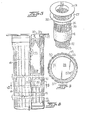
- FIG. 2 illustrates the various components of a filter assembly.
- each elongate tubular filter bag 14 is made of a gas permeable fabric and in a form somewhat similar to a sock, having one open end and one closed end.
- the filter assembly also includes an elongate tubular supporting frame 26, commonly termed a "cage".
- the supporting frame or cage 26 is of openwork construction for readily allowing the flow of air therethrough, and is typically formed of heavy wire.
- the supporting frame or cage 26 has an outwardly extending rim or flange 27 at the upper end thereof for securing the cage to the wall 11 of the filter housing, and the lower end of the cage 26 is closed by an end plate 28.
- the cage 26 is adapted to be positioned inside the tubular filter bag 14 so as to hold the filter bag in an open tubular configuration and prevent it from collapsing upon itself during the filtering operation as the particulate-laden gas passes inwardly therethrough.
- the diffuser tube 30 is of a size adapted for being slidingly received longitudinally within the (hollow) supporting cage 26.
- the diffuser tube 30 is preferably provided with an outturned lip or flange 31 at the upper end thereof to assist in mounting the diffuser tube in place within the tubular supporting cage 26 and is also preferably provided at the lower end thereof with a ringlike spacer 32 or other suitable means to assist in maintaining the diffuser tube 30 centered within the surrounding cage.
- the diameter of the diffuser tube 30 is as large as possible so as to maximize the cross-sectional area of the diffuser tube while still allowing sufficient clearance between the diffuser tube and the cage 26 to permit sliding the diffuser tube into position within the cage and so that the diffuser tube will be substantially out of contact with the surrounding cage 26 and the filter bag 14.
- the outside diameter of the diffuser tube is about 2 to 5 cms (one to two inches) less than the inside diameter of the surrounding cage.
- the diffuser tube 30 may be formed of any suitable material which is capable of withstanding the conditions to which the filtering system is subjected.
- any suitable material which is capable of withstanding the conditions to which the filtering system is subjected.
- stainless steel is the preferred material.
- other materials may be suitable.
- the diffuser tube is of a circular cross section for being received within a surrounding supporting cage which is also of a circular cross section.
- the diffuser tube may be constructed of a different cross-sectional shape, such as oval for example, in order to fit within cages of other cross-sectional shapes.
- the diffuser tube 30 has perforations or openings 33 formed therein which serve for diffusing and distributing air throughout the filter bag when a periodic reverse flow of purging air is directed into the outlet end of the filter and into the diffuser tube.
- the perforations 33 are located substantially throughout the longitudinal and circumferential extent of the diffuser tube.
- the size and spacing of the perforations 33 is such that the diffuser tube has a void area of from about 35% to about 50%.
- the hollow perforated diffuser tube 30 of the present invention performs the function of diffusing and distributing the pulse or blast of cleaning air over the entire filter bag to thus provide much more effective and efficient cleaning of the filter bag. Tests have shown that up to 30% by weight more particulate material is removed from the filter bag as a result of the provision of the diffuser tube. Also, as a result of the enhanced cleaning, the volume of air which can flow through the filter at a given pressure drop operation is increased by some two to three times.
- the concentration of the cleaning air pulse adjacent the outlet end of the filter under the prior conventional arrangement also resulted in excessive flexing of the filter bag in that area.
- the more even distribution of the cleaning air as a result of the provision of the diffuser tube avoids this overflexing of the filter bag and thereby contributes to an increased useful life of the bag.
- Another factor which has heretofore contributed to the wear of the filter bag is the high velocity flow of air along the inside surfaces of the filter bag adjacent the outlet end of the filter. While the velocity of the air as it passes through the filter bag is relatively low, the air velocity interiorly of the filter bag adjacent the outlet end thereof is considerably higher because of the reduced cross-sectional flow area as compared to the overall surface area of the filter bag. This relatively high velocity air, together with the dust particles which pass through the filter bag and are entrained in the air, would normally flow across the interior surface of the filter bag and cause additional wear and abrasion in this area.
- the provision of the diffuser tube of the present invention inside the filter bag serves to separate or insulate the interior surface of the filter bag from this high velocity air, thereby further contributing to the increased life of the filter bag.
- the diffuser tube 30 is of a length somewhat less than the overall length of the supporting cage 26 and that the lower end of the diffuser tube 30 is open. In order to achieve the benefits and advantages of the present invention, it has been determined that it is not necessary for the diffuser tube 30 to extend the full length of the surrounding cage, although it may if so desired.
- the diffuser tube 30 should preferably have a length of at least about half the overall length of the surrounding cage 26, and most desirably about two-thirds to three-fourths the overall length of the cage. However, it has been determined that lengths considerably less than these preferred lengths still provide very beneficial results as compared to the results obtained in accordance with the prior art arrangement where no diffuser tube is employed.
- Comparative flow tests were conducted using a laboratory filter testing apparatus having two zones, each zone provided with twelve bag-type filters of similar construction.
- the filters of one zone were of the conventional construction and included only the filter bags and their supporting cages, while the filters of the second zone (Zone 2) were equipped with perforated diffuser tubes in accordance with the invention.
- Tests were run at varying air flow rates providing an air-to-cloth (A/C) ratio of 6, 8 and 12 cubic metres per minute per square metre or (cubic feet per minute per square foot of filter area) and with a fixed dust feed of 170 gms per minute (six ounces per minute), which at 6 A/C ratio would be 3.43 gms per cu metre (1.5 grains per cubic foot) dust load.
- A/C air-to-cloth
- Table I show the air volumes handled by each zone, at an A/C ratio of 6 with new filter bags, and the associated percentage of air flow handled by each zone.
- the filters were then cleaned by a reverse purging flow of air through the filters.
- the data of Table II show the air flow handled by each zone after cleaning.
- the filters of Zone 1 handled only 26.1% of the air flow while the filters of Zone 2 handled 73.9% of the air flow. This shows that the filters equipped with the diffuser tubes of the invention were much more effectively cleaned than the conventional filters of Zone 1. Even after eight minutes of operation, the filters of Zone 2 remained considerably cleaner than those of Zone 1, handling 62% of the air flow as compared to 38% of the air flow in Zone 1.
Priority Applications (1)
| Application Number | Priority Date | Filing Date | Title |
|---|---|---|---|
| AT80303276T ATE18013T1 (de) | 1979-09-18 | 1980-09-17 | Schlauchfilter. |
Applications Claiming Priority (2)
| Application Number | Priority Date | Filing Date | Title |
|---|---|---|---|
| US06/076,605 US4231770A (en) | 1979-09-18 | 1979-09-18 | Bag-type filter apparatus with internal air diffuser |
| US76605 | 1979-09-18 |
Publications (3)
| Publication Number | Publication Date |
|---|---|
| EP0026087A2 EP0026087A2 (en) | 1981-04-01 |
| EP0026087A3 EP0026087A3 (en) | 1982-01-27 |
| EP0026087B1 true EP0026087B1 (en) | 1986-02-19 |
Family
ID=22133091
Family Applications (1)
| Application Number | Title | Priority Date | Filing Date |
|---|---|---|---|
| EP80303276A Expired EP0026087B1 (en) | 1979-09-18 | 1980-09-17 | Bag-type filter apparatus |
Country Status (23)
| Country | Link |
|---|---|
| US (1) | US4231770A (ru) |
| EP (1) | EP0026087B1 (ru) |
| JP (1) | JPS5653719A (ru) |
| KR (1) | KR830001385B1 (ru) |
| AR (1) | AR220869A1 (ru) |
| AT (1) | ATE18013T1 (ru) |
| AU (1) | AU531746B2 (ru) |
| BR (1) | BR8005958A (ru) |
| CA (1) | CA1151081A (ru) |
| DD (1) | DD152725A5 (ru) |
| DE (1) | DE3071432D1 (ru) |
| DK (1) | DK154006C (ru) |
| ES (1) | ES8106090A1 (ru) |
| FI (1) | FI75097C (ru) |
| HK (1) | HK94787A (ru) |
| IL (1) | IL60940A (ru) |
| IN (1) | IN152765B (ru) |
| MX (1) | MX6945E (ru) |
| NO (1) | NO150865C (ru) |
| NZ (1) | NZ194746A (ru) |
| SG (1) | SG64787G (ru) |
| SU (1) | SU1037829A3 (ru) |
| ZA (1) | ZA805355B (ru) |
Families Citing this family (23)
| Publication number | Priority date | Publication date | Assignee | Title |
|---|---|---|---|---|
| US4289511A (en) * | 1979-09-18 | 1981-09-15 | Johnson Jr Allen S | Bag-type filter apparatus with venturi-supported air diffuser |
| US4280826A (en) * | 1979-09-18 | 1981-07-28 | Staclean Diffuser Company | Bag-type filter apparatus with high pressure air jet cleaning |
| US4297115A (en) * | 1979-09-18 | 1981-10-27 | Staclean Diffuser Company | Bag-type filter with air diffuser tubes of helical construction |
| US4357151A (en) * | 1981-02-25 | 1982-11-02 | American Precision Industries Inc. | Electrostatically augmented cartridge type dust collector and method |
| US4632680A (en) * | 1985-10-28 | 1986-12-30 | Carter-Day Co. | Planar sided air shaping inserts for filter bags |
| US4861353A (en) * | 1987-12-07 | 1989-08-29 | E. I. Du Pont De Nemours And Company | Filter element and assembly |
| JPH04150910A (ja) * | 1990-10-12 | 1992-05-25 | Sanko Seisakusho:Kk | バグフィルター集塵機の円筒形濾過体の保護装置 |
| EP0511725B1 (de) * | 1991-04-30 | 1996-08-28 | Paul Dr. Van Ackeren | Schlauchfilter |
| DE4123257A1 (de) * | 1991-07-13 | 1993-01-21 | Steinmueller Gmbh L & C | Verfahren zur abreinigung von staub von den aussenseiten von filterelementen und vorrichtung zur durchfuehrung des verfahrens |
| US5202021A (en) * | 1991-08-26 | 1993-04-13 | Hosokawa Micron International Inc. | Integrated molded collar, filter bag, cage and locking ring assembly for baghouses |
| US5562251A (en) * | 1993-09-03 | 1996-10-08 | Goyen Controls & Co. Pty. Limited | Gas nozzle for bag house cleaning systems |
| US5800580A (en) * | 1993-10-27 | 1998-09-01 | Feldt; Klas-Goran | Support cage for glass fiber bag filter for gas filtration |
| US6004366A (en) | 1994-11-23 | 1999-12-21 | Donaldson Company, Inc. | Reverse flow air filter arrangement and method |
| US5910247A (en) * | 1997-09-08 | 1999-06-08 | Outterside; W. Mark | Two element filter bag |
| KR100289640B1 (ko) * | 1999-04-16 | 2001-05-02 | 장인순 | 흡입팬, 직류형 싸이클론, 표준형 싸이클론 및 캔들형 필터를 일체화한 통합형 고효율 분진제거 장치 |
| AP1948A (en) * | 2001-11-13 | 2009-02-05 | Bhp Billiton Innovation Pty Ltd | An air distributor for a bioleaching system. |
| WO2008056405A1 (fr) * | 2006-11-06 | 2008-05-15 | Mitsubishi Heavy Industries, Ltd. | Collecteur de poussière |
| US7648563B2 (en) * | 2005-10-21 | 2010-01-19 | General Electric Company | Methods and apparatus for manufacturing and assembling a baghouse bag filter tensioning assembly |
| DE112012000984T5 (de) * | 2011-02-25 | 2014-02-20 | Donaldson Company, Inc. | Luftfilterpatronen; Komponenten von diesen; und Luftreinigeraufbauten |
| NL2011597C2 (en) | 2013-10-11 | 2015-04-14 | Pwn Technologies B V | Filter device having a diverging cleaning duct with internal partitions. |
| AU2014339999B2 (en) | 2013-10-24 | 2019-03-07 | Donaldson Company, Inc. | Support structure for pleated filter media and methods |
| CN107531479B (zh) | 2015-04-21 | 2020-07-03 | 唐纳森公司 | 过滤器组件以及方法 |
| WO2017151337A1 (en) | 2016-03-02 | 2017-09-08 | Donaldson Company, Inc. | Filter element having inner support and methods |
Family Cites Families (12)
| Publication number | Priority date | Publication date | Assignee | Title |
|---|---|---|---|---|
| DE152017C (ru) * | 1900-01-01 | |||
| US2828017A (en) * | 1954-03-16 | 1958-03-25 | Helmer A Ronningen | Automatic backwashing filter |
| US2731107A (en) * | 1954-05-07 | 1956-01-17 | Jr Henry J Hersey | Filter |
| GB909345A (en) * | 1960-05-18 | 1962-10-31 | Simon Ltd Henry | Improvements in or relating to air filters |
| US3594992A (en) * | 1969-04-01 | 1971-07-27 | Air Preheater | Cleaning arrangement for bag filter |
| SU453176A1 (ru) * | 1971-07-27 | 1974-12-15 | А. Д. Мальгин , В. Н. Саксин | Способ регенерации фильтрующих каркасиыхрукавов |
| CA991561A (en) * | 1972-06-14 | 1976-06-22 | John F. Phillippi | Method and apparatus for bag collection of dirt |
| SU443674A1 (ru) * | 1973-01-04 | 1974-09-25 | Предприятие П/Я А-7229 | Фильтр дл очистки газов |
| JPS5074260A (ru) * | 1973-11-06 | 1975-06-18 | ||
| JPS5175673U (ru) * | 1974-12-11 | 1976-06-14 | ||
| US4097255A (en) * | 1977-04-04 | 1978-06-27 | Samolis Alfonso A | Gas filter cleaning apparatus |
| SE410086B (sv) * | 1977-08-23 | 1979-09-24 | Alfa Laval Ab | Rorfilteranordning med stromningsfordelande element |
-
1979
- 1979-09-18 US US06/076,605 patent/US4231770A/en not_active Expired - Lifetime
-
1980
- 1980-08-22 NZ NZ194746A patent/NZ194746A/xx unknown
- 1980-08-25 CA CA000358929A patent/CA1151081A/en not_active Expired
- 1980-08-28 ZA ZA00805355A patent/ZA805355B/xx unknown
- 1980-08-31 IL IL60940A patent/IL60940A/xx unknown
- 1980-09-08 KR KR1019800003543A patent/KR830001385B1/ko active
- 1980-09-16 FI FI802900A patent/FI75097C/fi not_active IP Right Cessation
- 1980-09-16 JP JP12846680A patent/JPS5653719A/ja active Granted
- 1980-09-16 AR AR282553A patent/AR220869A1/es active
- 1980-09-17 NO NO802755A patent/NO150865C/no unknown
- 1980-09-17 AT AT80303276T patent/ATE18013T1/de not_active IP Right Cessation
- 1980-09-17 EP EP80303276A patent/EP0026087B1/en not_active Expired
- 1980-09-17 IN IN1062/CAL/80A patent/IN152765B/en unknown
- 1980-09-17 DE DE8080303276T patent/DE3071432D1/de not_active Expired
- 1980-09-17 BR BR8005958A patent/BR8005958A/pt not_active IP Right Cessation
- 1980-09-17 SU SU802986455A patent/SU1037829A3/ru active
- 1980-09-17 AU AU62488/80A patent/AU531746B2/en not_active Ceased
- 1980-09-17 ES ES495526A patent/ES8106090A1/es not_active Expired
- 1980-09-17 DK DK393980A patent/DK154006C/da not_active IP Right Cessation
- 1980-09-18 MX MX809037U patent/MX6945E/es unknown
- 1980-09-18 DD DD80223985A patent/DD152725A5/de not_active IP Right Cessation
-
1987
- 1987-08-13 SG SG647/87A patent/SG64787G/en unknown
- 1987-12-10 HK HK947/87A patent/HK94787A/xx unknown
Also Published As
| Publication number | Publication date |
|---|---|
| IL60940A0 (en) | 1980-10-26 |
| IN152765B (ru) | 1984-03-31 |
| BR8005958A (pt) | 1981-03-31 |
| FI802900A (fi) | 1981-03-19 |
| IL60940A (en) | 1983-11-30 |
| NZ194746A (en) | 1983-09-30 |
| EP0026087A2 (en) | 1981-04-01 |
| ES495526A0 (es) | 1981-08-01 |
| NO150865C (no) | 1985-01-09 |
| ES8106090A1 (es) | 1981-08-01 |
| MX6945E (es) | 1986-12-19 |
| CA1151081A (en) | 1983-08-02 |
| ATE18013T1 (de) | 1986-03-15 |
| FI75097B (fi) | 1988-01-29 |
| DK154006C (da) | 1989-02-20 |
| KR830003920A (ko) | 1983-06-30 |
| JPS5653719A (en) | 1981-05-13 |
| AR220869A1 (es) | 1980-11-28 |
| AU6248880A (en) | 1981-04-09 |
| KR830001385B1 (ko) | 1983-07-21 |
| DK154006B (da) | 1988-10-03 |
| JPS632643B2 (ru) | 1988-01-20 |
| NO802755L (no) | 1981-03-19 |
| NO150865B (no) | 1984-09-24 |
| AU531746B2 (en) | 1983-09-01 |
| HK94787A (en) | 1987-12-18 |
| DD152725A5 (de) | 1981-12-09 |
| SU1037829A3 (ru) | 1983-08-23 |
| SG64787G (en) | 1988-09-30 |
| DK393980A (da) | 1981-03-19 |
| US4231770A (en) | 1980-11-04 |
| DE3071432D1 (en) | 1986-03-27 |
| EP0026087A3 (en) | 1982-01-27 |
| ZA805355B (en) | 1981-10-28 |
| FI75097C (fi) | 1988-05-09 |
Similar Documents
| Publication | Publication Date | Title |
|---|---|---|
| EP0026087B1 (en) | Bag-type filter apparatus | |
| EP0026641B1 (en) | Bag-type filter apparatus | |
| EP0027038B1 (en) | Bag-type filter apparatus | |
| US4324571A (en) | Bag-type filter apparatus with air diffuser having extended bag support | |
| EP0755295B1 (en) | Air filter assembly for filtering air with particulate matter | |
| US4297115A (en) | Bag-type filter with air diffuser tubes of helical construction | |
| JPS602085B2 (ja) | 簡潔なダスト・フイルタ・アセンブリ | |
| US5531798A (en) | Eliminating ash bridging in ceramic filters | |
| US5110331A (en) | Dust collector with re-entrainment prevention walls | |
| US3488039A (en) | Filter bed for dust collector | |
| US5242472A (en) | Flow restrictor in a pulse cleaning system | |
| US4289511A (en) | Bag-type filter apparatus with venturi-supported air diffuser | |
| EP0682971A1 (en) | Filtering apparatus | |
| EP0083169B1 (en) | Filter apparatus having secondary gas discharge system | |
| FI76706B (fi) | Metod och apparat foer oekande av effektiviteten hos internt samlande filterpaosar. | |
| US20200384400A1 (en) | Top inlet vacuum pulse cleaning dust collector | |
| FI87540B (fi) | Foerfarande och anordning foer matning av gas till partikelfilter | |
| SU1139477A1 (ru) | Рукавный фильтр дл очистки газов | |
| RU2283685C1 (ru) | Фильтр | |
| RU2211078C1 (ru) | Рукавный фильтр | |
| US3513639A (en) | Bag filter cleaning | |
| KR820000448B1 (ko) | 벤츄리 케이지 조립체 |
Legal Events
| Date | Code | Title | Description |
|---|---|---|---|
| PUAI | Public reference made under article 153(3) epc to a published international application that has entered the european phase |
Free format text: ORIGINAL CODE: 0009012 |
|
| AK | Designated contracting states |
Designated state(s): AT BE CH DE FR GB IT LU NL SE |
|
| PUAL | Search report despatched |
Free format text: ORIGINAL CODE: 0009013 |
|
| 17P | Request for examination filed |
Effective date: 19811026 |
|
| AK | Designated contracting states |
Designated state(s): AT BE CH DE FR GB IT LU NL SE |
|
| RHK1 | Main classification (correction) |
Ipc: B01D 46/04 |
|
| GRAA | (expected) grant |
Free format text: ORIGINAL CODE: 0009210 |
|
| RAP1 | Party data changed (applicant data changed or rights of an application transferred) |
Owner name: JOHNSON, FRANCES HEDRICK |
|
| RIN1 | Information on inventor provided before grant (corrected) |
Inventor name: JOHNSON, ALLEN STALING JR. (DECEASED) |
|
| AK | Designated contracting states |
Designated state(s): AT BE CH DE FR GB IT LI LU NL SE |
|
| REF | Corresponds to: |
Ref document number: 18013 Country of ref document: AT Date of ref document: 19860315 Kind code of ref document: T |
|
| REF | Corresponds to: |
Ref document number: 3071432 Country of ref document: DE Date of ref document: 19860327 |
|
| ITF | It: translation for a ep patent filed |
Owner name: ING. C. CORRADINI & C. S.R.L. |
|
| ET | Fr: translation filed | ||
| PLBE | No opposition filed within time limit |
Free format text: ORIGINAL CODE: 0009261 |
|
| STAA | Information on the status of an ep patent application or granted ep patent |
Free format text: STATUS: NO OPPOSITION FILED WITHIN TIME LIMIT |
|
| 26N | No opposition filed | ||
| PGFP | Annual fee paid to national office [announced via postgrant information from national office to epo] |
Ref country code: LU Payment date: 19920715 Year of fee payment: 13 |
|
| PGFP | Annual fee paid to national office [announced via postgrant information from national office to epo] |
Ref country code: BE Payment date: 19920807 Year of fee payment: 13 |
|
| PGFP | Annual fee paid to national office [announced via postgrant information from national office to epo] |
Ref country code: DE Payment date: 19920817 Year of fee payment: 13 |
|
| PGFP | Annual fee paid to national office [announced via postgrant information from national office to epo] |
Ref country code: SE Payment date: 19920824 Year of fee payment: 13 |
|
| PGFP | Annual fee paid to national office [announced via postgrant information from national office to epo] |
Ref country code: GB Payment date: 19920917 Year of fee payment: 13 |
|
| PGFP | Annual fee paid to national office [announced via postgrant information from national office to epo] |
Ref country code: FR Payment date: 19920918 Year of fee payment: 13 |
|
| ITTA | It: last paid annual fee | ||
| PGFP | Annual fee paid to national office [announced via postgrant information from national office to epo] |
Ref country code: NL Payment date: 19920930 Year of fee payment: 13 Ref country code: AT Payment date: 19920930 Year of fee payment: 13 |
|
| PGFP | Annual fee paid to national office [announced via postgrant information from national office to epo] |
Ref country code: CH Payment date: 19921029 Year of fee payment: 13 |
|
| EPTA | Lu: last paid annual fee | ||
| PG25 | Lapsed in a contracting state [announced via postgrant information from national office to epo] |
Ref country code: LU Free format text: LAPSE BECAUSE OF NON-PAYMENT OF DUE FEES Effective date: 19930917 Ref country code: GB Effective date: 19930917 Ref country code: AT Effective date: 19930917 |
|
| PG25 | Lapsed in a contracting state [announced via postgrant information from national office to epo] |
Ref country code: SE Effective date: 19930918 |
|
| PG25 | Lapsed in a contracting state [announced via postgrant information from national office to epo] |
Ref country code: LI Effective date: 19930930 Ref country code: CH Effective date: 19930930 Ref country code: BE Effective date: 19930930 |
|
| BERE | Be: lapsed |
Owner name: JOHNSON FRANCES HEDRICK Effective date: 19930930 |
|
| PG25 | Lapsed in a contracting state [announced via postgrant information from national office to epo] |
Ref country code: NL Effective date: 19940401 |
|
| GBPC | Gb: european patent ceased through non-payment of renewal fee |
Effective date: 19930917 |
|
| NLV4 | Nl: lapsed or anulled due to non-payment of the annual fee | ||
| PG25 | Lapsed in a contracting state [announced via postgrant information from national office to epo] |
Ref country code: FR Free format text: LAPSE BECAUSE OF NON-PAYMENT OF DUE FEES Effective date: 19940531 |
|
| REG | Reference to a national code |
Ref country code: CH Ref legal event code: PL |
|
| PG25 | Lapsed in a contracting state [announced via postgrant information from national office to epo] |
Ref country code: DE Effective date: 19940601 |
|
| REG | Reference to a national code |
Ref country code: FR Ref legal event code: ST |
|
| EUG | Se: european patent has lapsed |
Ref document number: 80303276.2 Effective date: 19940410 |