EP0025726B1 - Anlage zum Kontaktieren einer Flüssigkeit mit einem Gas - Google Patents
Anlage zum Kontaktieren einer Flüssigkeit mit einem Gas Download PDFInfo
- Publication number
- EP0025726B1 EP0025726B1 EP80401070A EP80401070A EP0025726B1 EP 0025726 B1 EP0025726 B1 EP 0025726B1 EP 80401070 A EP80401070 A EP 80401070A EP 80401070 A EP80401070 A EP 80401070A EP 0025726 B1 EP0025726 B1 EP 0025726B1
- Authority
- EP
- European Patent Office
- Prior art keywords
- installation
- gas
- sub
- unit
- tubes
- Prior art date
- Legal status (The legal status is an assumption and is not a legal conclusion. Google has not performed a legal analysis and makes no representation as to the accuracy of the status listed.)
- Expired
Links
Images

Classifications
-
- F—MECHANICAL ENGINEERING; LIGHTING; HEATING; WEAPONS; BLASTING
- F28—HEAT EXCHANGE IN GENERAL
- F28F—DETAILS OF HEAT-EXCHANGE AND HEAT-TRANSFER APPARATUS, OF GENERAL APPLICATION
- F28F25/00—Component parts of trickle coolers
- F28F25/02—Component parts of trickle coolers for distributing, circulating, and accumulating liquid
- F28F25/08—Splashing boards or grids, e.g. for converting liquid sprays into liquid films; Elements or beds for increasing the area of the contact surface
- F28F25/087—Vertical or inclined sheets; Supports or spacers
-
- F—MECHANICAL ENGINEERING; LIGHTING; HEATING; WEAPONS; BLASTING
- F28—HEAT EXCHANGE IN GENERAL
- F28B—STEAM OR VAPOUR CONDENSERS
- F28B1/00—Condensers in which the steam or vapour is separate from the cooling medium by walls, e.g. surface condenser
- F28B1/06—Condensers in which the steam or vapour is separate from the cooling medium by walls, e.g. surface condenser using air or other gas as the cooling medium
-
- F—MECHANICAL ENGINEERING; LIGHTING; HEATING; WEAPONS; BLASTING
- F28—HEAT EXCHANGE IN GENERAL
- F28C—HEAT-EXCHANGE APPARATUS, NOT PROVIDED FOR IN ANOTHER SUBCLASS, IN WHICH THE HEAT-EXCHANGE MEDIA COME INTO DIRECT CONTACT WITHOUT CHEMICAL INTERACTION
- F28C1/00—Direct-contact trickle coolers, e.g. cooling towers
-
- F—MECHANICAL ENGINEERING; LIGHTING; HEATING; WEAPONS; BLASTING
- F28—HEAT EXCHANGE IN GENERAL
- F28F—DETAILS OF HEAT-EXCHANGE AND HEAT-TRANSFER APPARATUS, OF GENERAL APPLICATION
- F28F25/00—Component parts of trickle coolers
-
- F—MECHANICAL ENGINEERING; LIGHTING; HEATING; WEAPONS; BLASTING
- F28—HEAT EXCHANGE IN GENERAL
- F28F—DETAILS OF HEAT-EXCHANGE AND HEAT-TRANSFER APPARATUS, OF GENERAL APPLICATION
- F28F25/00—Component parts of trickle coolers
- F28F25/02—Component parts of trickle coolers for distributing, circulating, and accumulating liquid
- F28F25/08—Splashing boards or grids, e.g. for converting liquid sprays into liquid films; Elements or beds for increasing the area of the contact surface
-
- F—MECHANICAL ENGINEERING; LIGHTING; HEATING; WEAPONS; BLASTING
- F28—HEAT EXCHANGE IN GENERAL
- F28F—DETAILS OF HEAT-EXCHANGE AND HEAT-TRANSFER APPARATUS, OF GENERAL APPLICATION
- F28F2280/00—Mounting arrangements; Arrangements for facilitating assembling or disassembling of heat exchanger parts
- F28F2280/02—Removable elements
-
- Y—GENERAL TAGGING OF NEW TECHNOLOGICAL DEVELOPMENTS; GENERAL TAGGING OF CROSS-SECTIONAL TECHNOLOGIES SPANNING OVER SEVERAL SECTIONS OF THE IPC; TECHNICAL SUBJECTS COVERED BY FORMER USPC CROSS-REFERENCE ART COLLECTIONS [XRACs] AND DIGESTS
- Y02—TECHNOLOGIES OR APPLICATIONS FOR MITIGATION OR ADAPTATION AGAINST CLIMATE CHANGE
- Y02B—CLIMATE CHANGE MITIGATION TECHNOLOGIES RELATED TO BUILDINGS, e.g. HOUSING, HOUSE APPLIANCES OR RELATED END-USER APPLICATIONS
- Y02B30/00—Energy efficient heating, ventilation or air conditioning [HVAC]
- Y02B30/70—Efficient control or regulation technologies, e.g. for control of refrigerant flow, motor or heating
-
- Y—GENERAL TAGGING OF NEW TECHNOLOGICAL DEVELOPMENTS; GENERAL TAGGING OF CROSS-SECTIONAL TECHNOLOGIES SPANNING OVER SEVERAL SECTIONS OF THE IPC; TECHNICAL SUBJECTS COVERED BY FORMER USPC CROSS-REFERENCE ART COLLECTIONS [XRACs] AND DIGESTS
- Y10—TECHNICAL SUBJECTS COVERED BY FORMER USPC
- Y10S—TECHNICAL SUBJECTS COVERED BY FORMER USPC CROSS-REFERENCE ART COLLECTIONS [XRACs] AND DIGESTS
- Y10S261/00—Gas and liquid contact apparatus
- Y10S261/11—Cooling towers
Definitions
- the present invention relates to an installation for bringing a fluid into contact with a gas.
- Such installations are used in particular for the refrigeration of a fluid, for example water, by atmospheric air. They then comprise a heat exchange body, placed in an enclosure provided with air inlet and outlet openings, and in which the water to be cooled is brought directly or indirectly into contact with atmospheric air.
- the body is made up of batteries of parallel horizontal or vertical tubes in which the water to be cooled circulates, while atmospheric air passes through the batteries through the intervals provided between the tubes.
- the water is brought by a distribution network above the heat exchange body.
- exchange bodies are generally made of plastic materials such as polystyrene, ABS, polyethylene, polypropylene or polyvinyl chloride. All these materials are based on carbon and hydrogen and burn more or less easily. If, in the case of atmospheric refrigerants, the dangers of ignition of the exchange body are insignificant when the refrigerant is supplied with water, it is not the same when it is stopped and purged. In addition, in the case of atmospheric refrigerants. or more generally of installations for bringing a liquid into contact with a gas in which the fluid to be cooled or to be brought into contact with the gas is not water, possibilities of ignition may remain even when the installation is in operation. It is therefore essential to prevent a general ignition of the heat exchange body which would cause irreparable damage to the installation and, in the case where this body is made of polyvinyl chloride, the release of highly toxic chlorine compounds.
- plastic materials such as polystyrene, ABS, polyethylene, polypropylene or polyvinyl chloride. All these materials are based on carbon and
- the invention aims to provide an installation for bringing a liquid into contact with a gas, of the type in which the body for bringing the fluid into contact with the gas is suspended from a framework inside the enclosure as described , for example, in French patents Nos. 02405451, 2412047 and 1 408 931, which makes it possible to prevent an inflammation of the contacting body from spreading to the rest of the installation and, in the case where the body has a appropriate special structure, to prevent generalized inflammation thereof.
- the invention relates to an installation for bringing a fluid into contact with a gas.
- an enclosure provided at the lower part of its periphery with at least one gas inlet opening and at its upper part with at least one gas discharge opening and a body for bringing the fluid into contact with the gas in a " combustible material, said body being located in the enclosure above the gas outlet opening and being suspended from a frame by attachment means, characterized in that said means d the attachment comprises temperature-sensitive means suitable for causing the rupture of said attachment means in response to the detection of a predetermined temperature at most equal to the ignition temperature of the contacting body. if an outbreak of fire occurs in the contacting body, the temperature-sensitive means cause it to stall, which falls on the floor of the enclosure.
- the sensitive equipment of the installation is generally located at a height i important above the ground, the flames of this burning body cannot reach this equipment.
- the installation is an atmospheric refrigerant in which the water to be cooled is brought into direct contact with atmospheric air, it is equipped at its lower part with a basin for collecting the cooled water. , so that in case of stall the body falls into this basin whose water contributes to the extinction.
- the attachment means of each sub-assembly include temperature-sensitive means such as defined above.
- This embodiment allows the sub-assemblies to unhook individually in the event that they are inflamed and therefore contributes to avoiding generalized inflammation of the body.
- the atmospheric refrigerant shown comprises a veil 1 of concrete forming a chimney provided at its base with a peripheral air inlet opening 2 and at its upper part with an air exhaust opening 3.
- a heat exchange body 5 suspended from a frame by attachment means 7.
- the heat exchange body 5 of the type in which of the water is cooled and brought into direct contact with atmospheric air, this water being distributed to the upper part of the body 5 by a network of tubes 8.
- the cooled water falling in free fall from the lower part of the body 5 is collected in a basin 9 extending at the base of the enclosure 4. over the entire section thereof.
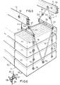
- FIG. 2 shows an exchange body 5 consisting of a number of sub-assemblies 10.
- Each sub-assembly 10 is constituted by a group of several blocks 11 in the shape of a rectangular parallelepiped superimposed and spaced vertically from one another. These blocks 11 have been shown schematically and can take any suitable form allowing direct contact of a liquid sprayed at their upper part with a gas which penetrates them by their lower part.
- the blocks 11 are suspended from each other by means of lines 12 formed by endless cables passing over the ends of pins 13 fixed horizontally in the blocks 11.
- the blocks 11 are hooked to each other in four points arranged symmetrically on the two opposite longest side faces of the blocks.
- the four hangers 12 of the upper block 11 are hooked to the respective ends of two pieces 14 formed by plastic tubes. These tubes 14 extend crosswise over the upper block 11 and intersect substantially above the center of this block.
- Two additional hangers 15 are further provided on each side of the blocks 11 between the respective ends of the two tubes 14 adjacent to this side and an additional pin 16 disposed in the middle of the longest side face of the lower block 11. These additional lines 15 are intended to prevent a deflection of the lower block 11, for example in the case where it would be frozen in freezing weather.
- Each sub-assembly 10 is suspended from the frame 6 by four lines 17 which are each hooked respectively to one end of a tube 14 and to a spindle 18 fixed in a beam 19 of the frame 6.
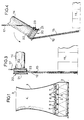
- Fig.3 shows in more detail the end portion 20 of a tube 14 to which are hung the lines 12, 15 and 17, which all consist of an endless cable.
- the end portion 20 has the form of a coil having an outer flange 21 and a flange 22 of smaller diameter on the side of the tube 14.
- an annular flange 23 projects on the cylindrical part of the coil between the flanges 21 and 22.
- the lower loop of the hanger 17 which supports the end part 20 embraces the lower part of the latter between the flange 23 and the flange 22.
- the upper loops of the hangers 12 and 15 embrace the upper part of the end part 20 and are arranged side by side between the flange 21 and the flange 23.
- the weight of the ignited subassemblies 10 exerts a moment which tends to tip the tubes 14.
- the tubes 14 are break in two at their middle part and tilt simultaneously as shown in Fig. 4.
- the lower loop of the hanger 17 then immediately escapes from the part 20 in the form of a coil thanks to the fact that the flange 22 has a small diameter.
- the four attachment points of the ignited sub-assembly 10 are then released so that it falls vertically towards the bottom of the enclosure 4. It will be noted that, thanks to the arrangement described above, the four points of hooking are released simultaneously, which avoids any tilting and any jamming of the sub-assembly during its fall. If the ignited sub-assembly falls into a basin 9 filled with water, the extinction is instantaneous. On the contrary, if the tank is empty or if no tank is provided in the case where the heat exchange body is of the indirect contact type. the ignited sub-assembly may continue to burn on the ground.
- the tubes 14 in a material capable of yielding at a temperature significantly lower than the ignition temperature of the blocks 11.
- the tubes 14 can be made of polypropylene which has a melting temperature close to 165 ° C. made of high density polyethylene with a melting temperature of the order of 130 ° C. Nylon which has a melting temperature below 250 ° C, or any other material having a melting temperature of the same order of magnitude.
- the detachment of the sub-assemblies 10 would therefore occur at a temperature of the order of 250 ° C. while the self-ignition point of polyvinyl chloride is of the order of 750 ° C. This therefore makes it possible to avoid a generalized inflammation of the exchange body even if a local hearth has been ignited inadvertently or maliciously, because the or at most the few sub-assemblies ignited by this hearth will drop before the neighboring sub-assemblies may have been ignited in turn due to the preferential vertical spread of the fire.
- Figs. 5 and 6 show a simplified embodiment of the invention.
- the mode of attachment of the blocks 11 of a sub-assembly 10 to each other is identical to that of FIG. 2.
- the upper loops of the lines 12 of the upper block 11 by which each sub-assembly 10 is suspended embrace the respective ends of two bars 24 extending transversely, that is to say parallel to the short sides of the blocks 11, between the big sides of these.
- These bars 24 have no particular role to play in the event of a fire and can therefore be made, for example, of metal.
- the attachment means 7 which connect each end of the bars 24 to the corresponding beam 19 comprise two hangers 25 and 26 formed by endless cables.
- the upper loops of the two lines 25 associated with the same bar 24 are hooked to a common pin 18 disposed vertically from the middle of the bar 24 in question.
- the lower loops of the lower hangers 26 are hooked to the respective ends of the bars 24 by any suitable means, for example by means of rings fixed to the ends of these bars.
- the lower loop of the hanger 25 and the upper loop of the hanger 26 of each of the hooking means 7 are linked together by a piece 27 in the form of a coil shown in more detail in FIG. 6.
- This coil has an axial dimension much greater than the axial size presented by the above-mentioned loops on the coil and the diameters of the flanges 28 and 29 thereof are relatively large so that, as shown in FIG.
- the coil 27 takes an oblique position in which the lines 25 and 26 tend to escape from the coil but are retained by the flanges thereof.
- the coils 27 are made of one of the aforementioned materials having a relatively low melting temperature, so that in the event of a rise in temperature due to inflammation the flanges 28 subjected to the stress of the lines 25 and 26 se. deform and allow it to escape the coil 27, which allows the sub-assembly 10 to fall.
- this arrangement does not allow the simultaneous release of the four attachment points of a sub-assembly 10 with as much certainty as in the first embodiment, it has the advantage over the latter of requiring only two pins 18 per sub-assembly 10, which simplifies mounting and reduces the cost of the exchange body.
- This arrangement would have the advantage of increasing the probability of a simultaneous release of the four attachment points of the subassembly 10.
- An equivalent effect could be obtained by arranging the tubes 14 of the embodiment of FIG. 2, no longer obliquely, but transversely, that is to say like the bars 24. This arrangement would however be less advantageous than that shown in FIG. 2 because the two tubes 14 could fail with a slight time lag.
- the invention is not limited to the use of connecting pieces between the lines made of a material which gives way in the event of ignition, but that the attachment means 7 could be constituted by simple lines in one such material attached directly to the beams 19 and to the sub-assembly 10. More generally still, any means sensitive to temperature and adapted to cause the rupture of the attachment means 7 in response to the detection of an abnormally high temperature can be used.
Landscapes
- Engineering & Computer Science (AREA)
- Mechanical Engineering (AREA)
- General Engineering & Computer Science (AREA)
- Physics & Mathematics (AREA)
- Thermal Sciences (AREA)
- Heat-Exchange Devices With Radiators And Conduit Assemblies (AREA)
- Control Of Combustion (AREA)
- Manipulator (AREA)
Claims (9)
Priority Applications (1)
| Application Number | Priority Date | Filing Date | Title |
|---|---|---|---|
| AT80401070T ATE2576T1 (de) | 1979-09-03 | 1980-07-17 | Anlage zum kontaktieren einer fluessigkeit mit einem gas. |
Applications Claiming Priority (2)
| Application Number | Priority Date | Filing Date | Title |
|---|---|---|---|
| FR7921986 | 1979-09-03 | ||
| FR7921986A FR2464080A1 (fr) | 1979-09-03 | 1979-09-03 | Installation perfectionnee de mise en contact d'un fluide avec un gaz comprenant des moyens de protection contre l'incendie pour le corps de mise en contact |
Publications (2)
| Publication Number | Publication Date |
|---|---|
| EP0025726A1 EP0025726A1 (de) | 1981-03-25 |
| EP0025726B1 true EP0025726B1 (de) | 1983-02-16 |
Family
ID=9229303
Family Applications (1)
| Application Number | Title | Priority Date | Filing Date |
|---|---|---|---|
| EP80401070A Expired EP0025726B1 (de) | 1979-09-03 | 1980-07-17 | Anlage zum Kontaktieren einer Flüssigkeit mit einem Gas |
Country Status (5)
| Country | Link |
|---|---|
| US (1) | US4269794A (de) |
| EP (1) | EP0025726B1 (de) |
| AT (1) | ATE2576T1 (de) |
| DE (1) | DE3062030D1 (de) |
| FR (1) | FR2464080A1 (de) |
Families Citing this family (8)
| Publication number | Priority date | Publication date | Assignee | Title |
|---|---|---|---|---|
| US4591462A (en) * | 1985-07-03 | 1986-05-27 | Hamon-Sobelco | Fire control system for a gas and liquid contact apparatus |
| FR2882136B1 (fr) * | 2005-02-17 | 2007-05-11 | Jacir Air Traitement Sa | Corps d'echange thermique adapte a une tour de refroidissement, tour de refroidissement et procede d'assemblage associes |
| DE102010007873A1 (de) * | 2010-02-13 | 2011-08-18 | Hewitech GmbH & Co. KG, 48607 | Einbau für einen Kühlturm und Kühlturm mit mehreren derartigen Einbauten |
| US9400144B2 (en) * | 2013-03-13 | 2016-07-26 | Spx Cooling Technologies, Inc. | Modular counterflow fill hanging system apparatus and method |
| US10240877B2 (en) | 2013-11-12 | 2019-03-26 | Spx Cooling Technologies, Inc. | Splash bar module and method of installation |
| US10302377B2 (en) | 2013-11-12 | 2019-05-28 | Spx Cooling Technologies, Inc. | Splash bar module and method of installation |
| WO2018100224A1 (en) * | 2016-11-29 | 2018-06-07 | Outotec (Finland) Oy | Method and arrangement for suspending a curtain inside a cylindrical cooling space of a cooling tower |
| JP2022522432A (ja) * | 2019-02-25 | 2022-04-19 | レール・リキード-ソシエテ・アノニム・プール・レテュード・エ・レクスプロワタシオン・デ・プロセデ・ジョルジュ・クロード | 熱及び物質を交換する装置 |
Family Cites Families (16)
| Publication number | Priority date | Publication date | Assignee | Title |
|---|---|---|---|---|
| US2689613A (en) * | 1952-03-14 | 1954-09-21 | James S Whatley | Fire extinguisher and alarm |
| US2718290A (en) * | 1953-03-16 | 1955-09-20 | Lcon J Segil | Safety drop-out means for ceiling panels |
| US2800965A (en) * | 1953-07-09 | 1957-07-30 | Benjamin Electric Mfg Co | Light-transmitting plastic sheet panels |
| US2772742A (en) * | 1954-07-12 | 1956-12-04 | Plax Corp | Ceiling construction |
| US2984991A (en) * | 1958-03-24 | 1961-05-23 | Phillips Petroleum Co | Cooling tower and its safe operation |
| US3062298A (en) * | 1960-07-15 | 1962-11-06 | Willard L Nash | Fire guard ceiling support |
| US3208534A (en) * | 1961-09-07 | 1965-09-28 | Grinnell Corp | Means for protecting a water cooling tower |
| US3246432A (en) * | 1962-10-26 | 1966-04-19 | Owens Corning Fiberglass Corp | Heat sensitive suspended ceiling structure |
| US3227429A (en) * | 1963-02-04 | 1966-01-04 | American Radiator & Standard | Mass transfer packing |
| US3395515A (en) * | 1964-03-16 | 1968-08-06 | William Stanley Lovely | Cooling towers |
| SE311371B (de) * | 1966-01-26 | 1969-06-09 | Munters C | |
| US3894127A (en) * | 1969-09-11 | 1975-07-08 | Marley Co | Fill assembly structure for cross flow water cooling tower |
| US3751017A (en) * | 1971-04-23 | 1973-08-07 | Hamon Sobelco Sa | Cooling tower |
| US3834681A (en) * | 1972-08-17 | 1974-09-10 | Marley Co | Fireproof, prefab fill support structure for cooling tower |
| DE2421400C2 (de) * | 1974-05-03 | 1986-09-18 | Dynamit Nobel Ag, 5210 Troisdorf | Rotationskraftelement |
| FR2405451A1 (fr) * | 1977-10-07 | 1979-05-04 | Hamon | Echangeur de chaleur, notamment pour refrigerant atmospherique |
-
1979
- 1979-09-03 FR FR7921986A patent/FR2464080A1/fr active Granted
-
1980
- 1980-07-11 US US06/168,686 patent/US4269794A/en not_active Expired - Lifetime
- 1980-07-17 AT AT80401070T patent/ATE2576T1/de active
- 1980-07-17 DE DE8080401070T patent/DE3062030D1/de not_active Expired
- 1980-07-17 EP EP80401070A patent/EP0025726B1/de not_active Expired
Also Published As
| Publication number | Publication date |
|---|---|
| FR2464080A1 (fr) | 1981-03-06 |
| DE3062030D1 (en) | 1983-03-24 |
| EP0025726A1 (de) | 1981-03-25 |
| US4269794A (en) | 1981-05-26 |
| FR2464080B1 (de) | 1983-08-12 |
| ATE2576T1 (de) | 1983-03-15 |
Similar Documents
| Publication | Publication Date | Title |
|---|---|---|
| EP0025726B1 (de) | Anlage zum Kontaktieren einer Flüssigkeit mit einem Gas | |
| US9215950B2 (en) | Portable grill assembly | |
| FR2464722A1 (fr) | Procede et dispositif pour delimiter un passage a travers une nappe de fluide inflammable | |
| FR2949641A1 (fr) | Dispositif de confinement | |
| CA1141607A (fr) | Chaudiere, notamment pour installation de chauffage | |
| FR2676582A1 (fr) | Dispositif de recuperation et de refroidissement du cóoeur d'un reacteur nucleaire en fusion, a la suite d'un accident. | |
| FR3013422B1 (fr) | Poele a granules et son procede de fonctionnement | |
| FR2800444A1 (fr) | Emetteur sureleve de chauffage a rayonnement infrarouge et lumineux au gaz en particulier pour alimentation en tres basse pression | |
| FR2490880A1 (fr) | Bouchon a prise d'air pour accumulateur | |
| WO2014080142A9 (fr) | Dispositif pour ameliorer la combustion dans une cheminee | |
| EP0211817A1 (de) | Feuerüberwachungssystem für einen Apparat zum Kontaktieren eines Gases mit einer Flüssigkeit | |
| EP0115242B1 (de) | Rostelement aus Metallguss mit integriertem Ankerelement zum Fest-Fluid-Wärmeaustausch bei sehr hoher Temperatur | |
| WO1991013817A1 (fr) | Conteneur pour le transport d'un materiau en etat solide | |
| BE1004116A6 (fr) | Procede de carbonisation et installation pour la mise en oeuvre de ce procede. | |
| FR3068203B1 (fr) | Dispositif de flammage du sol | |
| EP1133666A1 (de) | Vorrichtung zur hochtemperaturwärmebehandlung von holzartigem material | |
| FR2778538A1 (fr) | Dispositif de reparation de rayonnages pour palettes | |
| FR3000477A1 (fr) | Prevention du debordement de liquide en dehors d'une installation a l'air libre de stockage de liquide. | |
| EP3257789A1 (de) | Behälter zum hinzufügen von abfällen, der einen feuerfesten verschluss umfasst | |
| FR1464086A (fr) | Perfectionnements aux installations pour la lutte contre la gelée | |
| FR2868514A1 (fr) | Grille d'incineration a gradins fixes refroidis a l'eau | |
| FR2638143A1 (en) | Device for fixing particularly crown rings, for example spraying rings, on tanks containing inflammable products | |
| EP0549416B1 (de) | Brenner mit Verbrennungsgitter und Heizungsanlage mit einem solchen Brenner | |
| FR2864904A1 (fr) | Dispositif enterre de protection d'objets contre le feu par formation d'un rideau de fluide | |
| FR2944689A1 (fr) | Appareil economique, polyvalent, transportable de cuisson directe ou indirecte, diffuseur de chaleur en acier forge, fonctionnant avec tous les types de combustibles naturels solides ou liquides |
Legal Events
| Date | Code | Title | Description |
|---|---|---|---|
| PUAI | Public reference made under article 153(3) epc to a published international application that has entered the european phase |
Free format text: ORIGINAL CODE: 0009012 |
|
| AK | Designated contracting states |
Designated state(s): AT BE CH DE GB IT LU NL SE |
|
| 17P | Request for examination filed |
Effective date: 19810309 |
|
| ITF | It: translation for a ep patent filed |
Owner name: ING. C. GREGORJ S.P.A. |
|
| GRAA | (expected) grant |
Free format text: ORIGINAL CODE: 0009210 |
|
| AK | Designated contracting states |
Designated state(s): AT BE CH DE GB IT LI LU NL SE |
|
| REF | Corresponds to: |
Ref document number: 2576 Country of ref document: AT Date of ref document: 19830315 Kind code of ref document: T |
|
| REF | Corresponds to: |
Ref document number: 3062030 Country of ref document: DE Date of ref document: 19830324 |
|
| PGFP | Annual fee paid to national office [announced via postgrant information from national office to epo] |
Ref country code: LU Payment date: 19830706 Year of fee payment: 4 |
|
| PG25 | Lapsed in a contracting state [announced via postgrant information from national office to epo] |
Ref country code: LU Free format text: LAPSE BECAUSE OF NON-PAYMENT OF DUE FEES Effective date: 19830731 |
|
| PGFP | Annual fee paid to national office [announced via postgrant information from national office to epo] |
Ref country code: CH Payment date: 19840627 Year of fee payment: 5 |
|
| PGFP | Annual fee paid to national office [announced via postgrant information from national office to epo] |
Ref country code: DE Payment date: 19840719 Year of fee payment: 5 |
|
| PGFP | Annual fee paid to national office [announced via postgrant information from national office to epo] |
Ref country code: SE Payment date: 19840930 Year of fee payment: 5 Ref country code: BE Payment date: 19840930 Year of fee payment: 5 |
|
| PGFP | Annual fee paid to national office [announced via postgrant information from national office to epo] |
Ref country code: AT Payment date: 19860623 Year of fee payment: 7 |
|
| PGFP | Annual fee paid to national office [announced via postgrant information from national office to epo] |
Ref country code: NL Payment date: 19870731 Year of fee payment: 8 |
|
| PG25 | Lapsed in a contracting state [announced via postgrant information from national office to epo] |
Ref country code: GB Effective date: 19880717 Ref country code: AT Effective date: 19880717 |
|
| PG25 | Lapsed in a contracting state [announced via postgrant information from national office to epo] |
Ref country code: SE Effective date: 19880718 |
|
| PG25 | Lapsed in a contracting state [announced via postgrant information from national office to epo] |
Ref country code: LI Effective date: 19880731 Ref country code: CH Effective date: 19880731 Ref country code: BE Effective date: 19880731 |
|
| BERE | Be: lapsed |
Owner name: HAMON-SOBELCO S.A. Effective date: 19880731 |
|
| PG25 | Lapsed in a contracting state [announced via postgrant information from national office to epo] |
Ref country code: NL Effective date: 19890201 |
|
| NLV4 | Nl: lapsed or anulled due to non-payment of the annual fee | ||
| GBPC | Gb: european patent ceased through non-payment of renewal fee | ||
| REG | Reference to a national code |
Ref country code: CH Ref legal event code: PL |
|
| PG25 | Lapsed in a contracting state [announced via postgrant information from national office to epo] |
Ref country code: DE Effective date: 19890401 |
|
| EUG | Se: european patent has lapsed |
Ref document number: 80401070.0 Effective date: 19890510 |
|
| PLBE | No opposition filed within time limit |
Free format text: ORIGINAL CODE: 0009261 |
|
| STAA | Information on the status of an ep patent application or granted ep patent |
Free format text: STATUS: NO OPPOSITION FILED WITHIN TIME LIMIT |