US4269794A - Fire control system for a gas and liquid contact apparatus - Google Patents
Fire control system for a gas and liquid contact apparatus Download PDFInfo
- Publication number
- US4269794A US4269794A US06/168,686 US16868680A US4269794A US 4269794 A US4269794 A US 4269794A US 16868680 A US16868680 A US 16868680A US 4269794 A US4269794 A US 4269794A
- Authority
- US
- United States
- Prior art keywords
- assembly
- sub
- contact
- suspension members
- hooked
- Prior art date
- Legal status (The legal status is an assumption and is not a legal conclusion. Google has not performed a legal analysis and makes no representation as to the accuracy of the status listed.)
- Expired - Lifetime
Links
Images


Classifications
-
- F—MECHANICAL ENGINEERING; LIGHTING; HEATING; WEAPONS; BLASTING
- F28—HEAT EXCHANGE IN GENERAL
- F28F—DETAILS OF HEAT-EXCHANGE AND HEAT-TRANSFER APPARATUS, OF GENERAL APPLICATION
- F28F25/00—Component parts of trickle coolers
- F28F25/02—Component parts of trickle coolers for distributing, circulating, and accumulating liquid
- F28F25/08—Splashing boards or grids, e.g. for converting liquid sprays into liquid films; Elements or beds for increasing the area of the contact surface
- F28F25/087—Vertical or inclined sheets; Supports or spacers
-
- F—MECHANICAL ENGINEERING; LIGHTING; HEATING; WEAPONS; BLASTING
- F28—HEAT EXCHANGE IN GENERAL
- F28B—STEAM OR VAPOUR CONDENSERS
- F28B1/00—Condensers in which the steam or vapour is separate from the cooling medium by walls, e.g. surface condenser
- F28B1/06—Condensers in which the steam or vapour is separate from the cooling medium by walls, e.g. surface condenser using air or other gas as the cooling medium
-
- F—MECHANICAL ENGINEERING; LIGHTING; HEATING; WEAPONS; BLASTING
- F28—HEAT EXCHANGE IN GENERAL
- F28C—HEAT-EXCHANGE APPARATUS, NOT PROVIDED FOR IN ANOTHER SUBCLASS, IN WHICH THE HEAT-EXCHANGE MEDIA COME INTO DIRECT CONTACT WITHOUT CHEMICAL INTERACTION
- F28C1/00—Direct-contact trickle coolers, e.g. cooling towers
-
- F—MECHANICAL ENGINEERING; LIGHTING; HEATING; WEAPONS; BLASTING
- F28—HEAT EXCHANGE IN GENERAL
- F28F—DETAILS OF HEAT-EXCHANGE AND HEAT-TRANSFER APPARATUS, OF GENERAL APPLICATION
- F28F25/00—Component parts of trickle coolers
-
- F—MECHANICAL ENGINEERING; LIGHTING; HEATING; WEAPONS; BLASTING
- F28—HEAT EXCHANGE IN GENERAL
- F28F—DETAILS OF HEAT-EXCHANGE AND HEAT-TRANSFER APPARATUS, OF GENERAL APPLICATION
- F28F25/00—Component parts of trickle coolers
- F28F25/02—Component parts of trickle coolers for distributing, circulating, and accumulating liquid
- F28F25/08—Splashing boards or grids, e.g. for converting liquid sprays into liquid films; Elements or beds for increasing the area of the contact surface
-
- F—MECHANICAL ENGINEERING; LIGHTING; HEATING; WEAPONS; BLASTING
- F28—HEAT EXCHANGE IN GENERAL
- F28F—DETAILS OF HEAT-EXCHANGE AND HEAT-TRANSFER APPARATUS, OF GENERAL APPLICATION
- F28F2280/00—Mounting arrangements; Arrangements for facilitating assembling or disassembling of heat exchanger parts
- F28F2280/02—Removable elements
-
- Y—GENERAL TAGGING OF NEW TECHNOLOGICAL DEVELOPMENTS; GENERAL TAGGING OF CROSS-SECTIONAL TECHNOLOGIES SPANNING OVER SEVERAL SECTIONS OF THE IPC; TECHNICAL SUBJECTS COVERED BY FORMER USPC CROSS-REFERENCE ART COLLECTIONS [XRACs] AND DIGESTS
- Y02—TECHNOLOGIES OR APPLICATIONS FOR MITIGATION OR ADAPTATION AGAINST CLIMATE CHANGE
- Y02B—CLIMATE CHANGE MITIGATION TECHNOLOGIES RELATED TO BUILDINGS, e.g. HOUSING, HOUSE APPLIANCES OR RELATED END-USER APPLICATIONS
- Y02B30/00—Energy efficient heating, ventilation or air conditioning [HVAC]
- Y02B30/70—Efficient control or regulation technologies, e.g. for control of refrigerant flow, motor or heating
-
- Y—GENERAL TAGGING OF NEW TECHNOLOGICAL DEVELOPMENTS; GENERAL TAGGING OF CROSS-SECTIONAL TECHNOLOGIES SPANNING OVER SEVERAL SECTIONS OF THE IPC; TECHNICAL SUBJECTS COVERED BY FORMER USPC CROSS-REFERENCE ART COLLECTIONS [XRACs] AND DIGESTS
- Y10—TECHNICAL SUBJECTS COVERED BY FORMER USPC
- Y10S—TECHNICAL SUBJECTS COVERED BY FORMER USPC CROSS-REFERENCE ART COLLECTIONS [XRACs] AND DIGESTS
- Y10S261/00—Gas and liquid contact apparatus
- Y10S261/11—Cooling towers
Definitions
- the present invention relates to gas and liquid contact installations.
- Gas and liquid contact installations are employed for the cooling of a fluid, for example water, by means of atmospheric air.
- a fluid for example water
- such installations comprise a heat exchange unit which is placed in an enclosure provided with an air inlet opening and an air outlet opening, and in which the water to be cooled is placed directly or indirectly in contact with the air between the air inlet and the air outlet from the enclosure.
- the unit In the case of indirect contact between the liquid and gas, the unit generally comprises batteries of parallel, horizontal or vertical tubes in which the water to be cooled flows, and the air of the atmosphere passes through the tube batteries by way of gaps or spaces between the tubes.
- a direct contact heat exchange the water is brought to the unit by a distribution system and is then sprayed or otherwise distributed on the heat exchange unit about which the air is passed.
- the latter may be constructed either in the form of an assembly of plates along which the water trickles in the form of thin films, or in the form of an assembly of surfaces which ensure the dispersion of the water in very fine droplets so as to form a mist which passes through the counter-current stream of air.
- the heat exchange units are generally constructed from plastic materials, such as polystyrene, ABS, polyethylene, polypropylene or polyvinyl chloride. These plastic materials are based on carbon and hydrogen and burn more or less easily.
- plastic materials such as polystyrene, ABS, polyethylene, polypropylene or polyvinyl chloride. These plastic materials are based on carbon and hydrogen and burn more or less easily.
- fire dangers are insignificant when the cooler is in operation and supplied with water; this is not so when the exchanger is shut down and drained.
- gas and liquid contact installations in which the fluid to be cooled or placed in contact with the gas is not water, possibilities of fire may exist even when the installation is operating.
- An object of the invention is to provide a gas and liquid contact installation in which the contact unit is suspended from a framework inside the enclosure, as disclosed, for example, in French Pat. Nos. 77 30 221; 77 38 119 and 1 408 931, which ensures that burning of a portion of the contact unit will not propagate to the rest of the installation.
- a gas and liquid contact installation comprising an enclosure provided in the lower part of its periphery with at least one gas inlet opening and in its upper end with at least one gas discharge opening, and a gas and liquid contact unit composed of a combustible material.
- the contact unit is disposed in the enclosure above the gas inlet opening from a framework by cables or draft members, characterized in that the draft members include temperature responsive means adapted to rupture in response to the detection of a predetermined temperature not greater than the flame temperature of the gas and liquid contact means.
- the contact units of such installations are usually located at great height above the ground, the flames of the burning unit do not reach other equipment of the installation.
- the installation is an atmospheric cooler in which the water to be cooled is in direct contact with the air of the atmosphere, there is provided, in its lower part, a basin for receiving the cooled water so that the water helps to extinguish the fire once a burning unit has dropped into the basin.
- each sub-assembly includes the temperature responsive means of the invention. This embodiment enables the sub-assemblies to become individually unhooked when they are enflamed and therefore tends to avoid further spreading of the fire to other contact units.
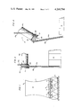
- FIG. 1 is a diagrammatic longitudinal sectional view of an atmospheric cooler of the natural draught type
- FIG. 2 is a perspective view of a heat exchange unit suspended from framework by cables and hooking means according to a preferred embodiment of the invention
- FIG. 3 is a detail view, to an enlarged scale, of a part of the suspension means of FIG. 2 showing its position during the normal operation of the installation;
- FIG. 4 is a view similar to FIG. 3, but showing the part upon the unhooking of the exchange unit
- FIG. 5 is a perspective view similar to FIG. 2 of another embodiment of the invention.
- FIG. 6 is a view, to an enlarged scale, of a detail of one of the hooking means of FIG. 5.
- the illustrated atmospheric cooler comprises a hollow concrete chimney 1 provided at its base with peripheral air inlet openings 2 and in its upper part with an air discharge opening 3.
- a heat exchange unit 5 suspended from a framework 6 by draft members and release members generally designated 7.
- the heat exchange unit 5 is of the type in which water is cooled by direct contact with the air of the atmosphere.
- the water is distributed in the upper part of the unit 5 by a system of tubes 8 having the usual spray heads or the like.
- the cooled water which falls freely from the lower part of the contact unit 5 is received in a basin 9 which extends across the entire base of the enclosure or chimney 4.
- cooler 1 an atmospheric cooler which operates by a direct contact of the water with the air of the atmosphere
- the ensuing description is not limited to this type of cooler as the invention is also applicable to coolers in which the fluid to be cooled is in indirect contact with the air of the atmosphere, and to coolers of the "compound” type comprising both indirect contact exchange units and direct contact exchange units, and to coolers of the "hybrid” type which comprise heat exchange units which operate both by direct contact and indirect contact, as described, for example, in U.S. Pat. Application Ser. No. 075,989 filed Sept. 17, 1979, and commonly owned with this application.
- the invention is also applicable to induced draught coolers employing suction or blower fans.
- FIG. 2 which shows an exchange unit 5 comprising a number of sub-assemblies 10.
- Each sub-assembly 10 comprises a group of parallel-sided elements 11 which are superimposed and vertically spaced apart from each other.
- These units 11 are shown diagrammatically and may have any suitable shape whereby it is possible to direct or spray a liquid against their upper ends to place the liquid in direct contact with a gas which enters them by way of their lower ends.
- the units 11 are held in suspension by means of suspension members 12a, 12b, 12c, etc. consisting of cables or draft members which pass around the ends of pins 13 fixed horizontally in the elements 11.
- the elements 11 are hooked to each other at four points which are disposed symmetrically on the two opposed longer sides of the elements.
- the four suspension members 12a, 12b, 12c, and 12d of the upper element are hooked to respective ends of two tubular members 14a and 14b formed of plastic materials. These tubes 14a and 14b extend in a cross configuration above the upper elements 11 and cross each other substantially above the centre of these elements.
- Two additional suspension members or cables 15a and 15b are provided on each side of the elements 11 and pass about the respective ends of the two tubes 14a and 14b and about an additional pin 16 disposed in the middle of the ends lateral side of each of the lower elements 11. These additional pins 16 prevent bending of the lower elements 11, for example, in the case where the latter would be frozen in cold weather.
- Each sub-assembly 10 is suspended from the framework 6 by four suspension cables 17a, 17b, 17c, and 17d which are each respectively hooked to one end of one of the tubes 14a and 14b, and to a pin 18 fixed in the girders 19 of the framework 6.
- FIG. 3 shows in more detail the end part 20 of tube 14a to which the suspension cables 12a, 15a, and 17a are hooked.
- Each end part 20 is reel-shaped and has an outer cheek or flange 21 and an inner cheek or flange 22 of smaller diameter which is adjacent to its tube 14a. Further, an annular flanhge 23 projects from the cylindrical part of the reel between the cheeks or flanges 21 and 22.
- the lower loop of the suspension cable 17a which supports the end part 20 is entrained about the lower part of the end part 20 between the flange 23 and the cheek or flange 22.
- the upper loops of the suspension members 12a and 15a encompass the upper part of the end part 20 and are disposed side-by-side between the flange 21 and the flange 23.
- Each end element 20 of each of the plurality of tubes 14 of the plurality of contact units 11 are similarly engaged by their respective cables 12, 15 and 17, as the case may be.
- the weight of the enflamed sub-assemblies 10 exert a torque on the tubes which tends to tilt or bend the heated tubes 14a and 14b.
- the tubes 14a and/or 14b break in two in the region of their middle part and simultaneously tilt in the manner shown in FIG. 4.
- the lower loop of the suspension cables 17a or 17b, etc. then immediately escapes from the reel-shaped parts 20 owing to the fact that the flanges 22 thereof have a small diameter.
- the four hooking points of the enflamed sub-assembly 10 are then released so that the latter falls vertically to the base of the enclosure 4. It will be noted that, owing to the previously-described arrangement, the four hooking points of the cables to the ends of a pair of tubes 14a and 14b are released simultaneously so that tilting or wedging of the burning sub-assembly is avoided during its fall. If the enflamed sub-assembly falls into the basin 9 filled with water, it is immediately extinguished.
- the enflamed sub-assembly may continue to burn on the ground.
- the height of the flames is of the order of 3 meters.
- the tubes 14a and 14b may be constructed of polypropylene which has a melting temperature in the neighborhood of 165° C., of high-density polyethylene whose melting temperature is of the order of 130° C., of nylon which has a melting temperature below 250° C., or of any other material which has a melting temperature of the same order of magnitude.
- the unhooking of the sub-assemblies 10 would therefore occur at a temperature of the order of 250° C. or lower, whereas the ignition temperature of polyvinyl chloride is of the order of 750° C. Consequently, this avoids a generalized burning of the entire exchange unit even if a local fire were lit accidentally or malevolently, since the sub-assembly, or at the most a few sub-assemblies, enflamed by the fire would be unhooked before the neighboring sub-assemblies have time to be engulfed by flames.
- FIGS. 5 and 6 show a simplified embodiment of the invention and in this embodiment, the manner of hooking the elements 11' of a sub-assembly 10' to each other is substantially identical to that of FIG. 2.
- the upper loops of the suspension members or cables 12'a, 12'b, 12'c and 12'd of the upper elements 11' by means of which each sub-assembly 10' is suspended surround the respective ends of two bars 24 which extend transversely, that is to say in a direction parallel to the smaller sides of the elements 11', and between the larger sides thereof.
- These bars 24 have no particular function to perform in the event of fire and can therefore be made, for example, from metal.
- the hooking means 7' which connect each end of the bars 24 to the corresponding girders 19' comprise two suspension members 25 and 26 formed as endless cables.
- the upper loops of the two suspension members 25 associated with the same bar 24 are hooked to a common pin 18' which is disposed vertically above the middle of the considered bar 24.
- the lower loops of the lower suspension members 26 are hooked to the respective ends of the bars 24 by any suitable means, for example, by rings 24' fixed to the ends of these bars.
- the lower loop of the suspension member 25 and the upper loop of the suspension member 26 of each of the hooking means 7' are interconnected by a member 27 in the form of a reel shown in more detail in FIG. 6.
- the reels 27 have an axial dimension which is distinctly larger than the overall axial size of the aforementioned loops on the reel and the diameters of the cheeks or flanges 28 and 29 of the latter are relatively large so that, as shown in FIG. 6, in the suspended position of a sub-assembly 10', the reels 27 assume an oblique position in which the suspension members 25 and 26 have a tendency to escape from the reel but are retained by the flanges 28 and 29 of the latter.
- the reels 27 are made from one of the aforementioned plastic materials having a relatively low melting temperature so that, in the event of a rise in temperature due to fire, the flanges 28 and 29, subjected to the stress of the suspension members 25 and 26, become deformed and allow the latter to escape from the softened reels 27 so that the considered sub-assembly 10' fails.
- this arrangement does not permit the simultaneous release of the four hooking points of a sub-assembly 10' with as much certainty as in the first embodiment, it has the advantage over the latter of requiring only two pins 18' per sub-assembly 10', which simplifies the assembly and reduces the cost of the exchange unit.
- the hooking means 7 or 7' could be formed by simple suspension members of heat sensitive material directly hooked to the girders 19 or 19' and to the sub-assembly 10 or 10'. More broadly, any temperature responsive release means adapted to result in the breakage of the hooking means 7 or 7' in response to the detection of an abnormally high temperature may be employed.
Landscapes
- Engineering & Computer Science (AREA)
- Mechanical Engineering (AREA)
- General Engineering & Computer Science (AREA)
- Physics & Mathematics (AREA)
- Thermal Sciences (AREA)
- Heat-Exchange Devices With Radiators And Conduit Assemblies (AREA)
- Control Of Combustion (AREA)
- Manipulator (AREA)
Applications Claiming Priority (2)
| Application Number | Priority Date | Filing Date | Title |
|---|---|---|---|
| FR7921986 | 1979-09-03 | ||
| FR7921986A FR2464080A1 (fr) | 1979-09-03 | 1979-09-03 | Installation perfectionnee de mise en contact d'un fluide avec un gaz comprenant des moyens de protection contre l'incendie pour le corps de mise en contact |
Publications (1)
| Publication Number | Publication Date |
|---|---|
| US4269794A true US4269794A (en) | 1981-05-26 |
Family
ID=9229303
Family Applications (1)
| Application Number | Title | Priority Date | Filing Date |
|---|---|---|---|
| US06/168,686 Expired - Lifetime US4269794A (en) | 1979-09-03 | 1980-07-11 | Fire control system for a gas and liquid contact apparatus |
Country Status (5)
| Country | Link |
|---|---|
| US (1) | US4269794A (de) |
| EP (1) | EP0025726B1 (de) |
| AT (1) | ATE2576T1 (de) |
| DE (1) | DE3062030D1 (de) |
| FR (1) | FR2464080A1 (de) |
Cited By (7)
| Publication number | Priority date | Publication date | Assignee | Title |
|---|---|---|---|---|
| US4591462A (en) * | 1985-07-03 | 1986-05-27 | Hamon-Sobelco | Fire control system for a gas and liquid contact apparatus |
| FR2882136A1 (fr) * | 2005-02-17 | 2006-08-18 | Jacir Air Traitement Sa | Corps d'echange thermique adapte a une tour de refroidissement, tour de refroidissement et procede d'assemblage associes |
| EP2357441A1 (de) * | 2010-02-13 | 2011-08-17 | Hewitech GmbH & Co. KG | Einbau für einen Kühlturm und Kühlturm mit mehreren derartigen Einbauten |
| US20140264971A1 (en) * | 2013-03-13 | 2014-09-18 | Spx Cooling Technologies, Inc. | Modular counterflow fill hanging system and apparatus method |
| US10240877B2 (en) | 2013-11-12 | 2019-03-26 | Spx Cooling Technologies, Inc. | Splash bar module and method of installation |
| US10302377B2 (en) | 2013-11-12 | 2019-05-28 | Spx Cooling Technologies, Inc. | Splash bar module and method of installation |
| US20220134304A1 (en) * | 2019-02-25 | 2022-05-05 | L'Air Liquide, Société Anonyme pour l'Etude et I'Exploitation des Procédés Georges Claude | Method for manufacturing an apparatus for exchanging heat and material |
Families Citing this family (1)
| Publication number | Priority date | Publication date | Assignee | Title |
|---|---|---|---|---|
| WO2018100224A1 (en) * | 2016-11-29 | 2018-06-07 | Outotec (Finland) Oy | Method and arrangement for suspending a curtain inside a cylindrical cooling space of a cooling tower |
Citations (11)
| Publication number | Priority date | Publication date | Assignee | Title |
|---|---|---|---|---|
| US2718290A (en) * | 1953-03-16 | 1955-09-20 | Lcon J Segil | Safety drop-out means for ceiling panels |
| US2772742A (en) * | 1954-07-12 | 1956-12-04 | Plax Corp | Ceiling construction |
| US2800965A (en) * | 1953-07-09 | 1957-07-30 | Benjamin Electric Mfg Co | Light-transmitting plastic sheet panels |
| US3062298A (en) * | 1960-07-15 | 1962-11-06 | Willard L Nash | Fire guard ceiling support |
| US3227429A (en) * | 1963-02-04 | 1966-01-04 | American Radiator & Standard | Mass transfer packing |
| US3246432A (en) * | 1962-10-26 | 1966-04-19 | Owens Corning Fiberglass Corp | Heat sensitive suspended ceiling structure |
| US3395515A (en) * | 1964-03-16 | 1968-08-06 | William Stanley Lovely | Cooling towers |
| US3395903A (en) * | 1966-01-26 | 1968-08-06 | Norback Per Gunnar | Air and water contact body as employed in cooling towers |
| US3751017A (en) * | 1971-04-23 | 1973-08-07 | Hamon Sobelco Sa | Cooling tower |
| US3834681A (en) * | 1972-08-17 | 1974-09-10 | Marley Co | Fireproof, prefab fill support structure for cooling tower |
| FR2405451A1 (fr) * | 1977-10-07 | 1979-05-04 | Hamon | Echangeur de chaleur, notamment pour refrigerant atmospherique |
Family Cites Families (5)
| Publication number | Priority date | Publication date | Assignee | Title |
|---|---|---|---|---|
| US2689613A (en) * | 1952-03-14 | 1954-09-21 | James S Whatley | Fire extinguisher and alarm |
| US2984991A (en) * | 1958-03-24 | 1961-05-23 | Phillips Petroleum Co | Cooling tower and its safe operation |
| US3208534A (en) * | 1961-09-07 | 1965-09-28 | Grinnell Corp | Means for protecting a water cooling tower |
| US3894127A (en) * | 1969-09-11 | 1975-07-08 | Marley Co | Fill assembly structure for cross flow water cooling tower |
| DE2421400C2 (de) * | 1974-05-03 | 1986-09-18 | Dynamit Nobel Ag, 5210 Troisdorf | Rotationskraftelement |
-
1979
- 1979-09-03 FR FR7921986A patent/FR2464080A1/fr active Granted
-
1980
- 1980-07-11 US US06/168,686 patent/US4269794A/en not_active Expired - Lifetime
- 1980-07-17 AT AT80401070T patent/ATE2576T1/de active
- 1980-07-17 DE DE8080401070T patent/DE3062030D1/de not_active Expired
- 1980-07-17 EP EP80401070A patent/EP0025726B1/de not_active Expired
Patent Citations (11)
| Publication number | Priority date | Publication date | Assignee | Title |
|---|---|---|---|---|
| US2718290A (en) * | 1953-03-16 | 1955-09-20 | Lcon J Segil | Safety drop-out means for ceiling panels |
| US2800965A (en) * | 1953-07-09 | 1957-07-30 | Benjamin Electric Mfg Co | Light-transmitting plastic sheet panels |
| US2772742A (en) * | 1954-07-12 | 1956-12-04 | Plax Corp | Ceiling construction |
| US3062298A (en) * | 1960-07-15 | 1962-11-06 | Willard L Nash | Fire guard ceiling support |
| US3246432A (en) * | 1962-10-26 | 1966-04-19 | Owens Corning Fiberglass Corp | Heat sensitive suspended ceiling structure |
| US3227429A (en) * | 1963-02-04 | 1966-01-04 | American Radiator & Standard | Mass transfer packing |
| US3395515A (en) * | 1964-03-16 | 1968-08-06 | William Stanley Lovely | Cooling towers |
| US3395903A (en) * | 1966-01-26 | 1968-08-06 | Norback Per Gunnar | Air and water contact body as employed in cooling towers |
| US3751017A (en) * | 1971-04-23 | 1973-08-07 | Hamon Sobelco Sa | Cooling tower |
| US3834681A (en) * | 1972-08-17 | 1974-09-10 | Marley Co | Fireproof, prefab fill support structure for cooling tower |
| FR2405451A1 (fr) * | 1977-10-07 | 1979-05-04 | Hamon | Echangeur de chaleur, notamment pour refrigerant atmospherique |
Cited By (12)
| Publication number | Priority date | Publication date | Assignee | Title |
|---|---|---|---|---|
| US4591462A (en) * | 1985-07-03 | 1986-05-27 | Hamon-Sobelco | Fire control system for a gas and liquid contact apparatus |
| EP0211817A1 (de) * | 1985-07-03 | 1987-02-25 | Hamon-Sobelco S.A. | Feuerüberwachungssystem für einen Apparat zum Kontaktieren eines Gases mit einer Flüssigkeit |
| FR2882136A1 (fr) * | 2005-02-17 | 2006-08-18 | Jacir Air Traitement Sa | Corps d'echange thermique adapte a une tour de refroidissement, tour de refroidissement et procede d'assemblage associes |
| EP1703041A1 (de) * | 2005-02-17 | 2006-09-20 | Jacir - Air Traitement | Wärmeaustauschkörper für einen Kühlturm und Zusammenbauverfahren desselben |
| EP2357441A1 (de) * | 2010-02-13 | 2011-08-17 | Hewitech GmbH & Co. KG | Einbau für einen Kühlturm und Kühlturm mit mehreren derartigen Einbauten |
| US20140264971A1 (en) * | 2013-03-13 | 2014-09-18 | Spx Cooling Technologies, Inc. | Modular counterflow fill hanging system and apparatus method |
| US9400144B2 (en) | 2013-03-13 | 2016-07-26 | Spx Cooling Technologies, Inc. | Modular counterflow fill hanging system apparatus and method |
| US9470463B2 (en) * | 2013-03-13 | 2016-10-18 | Spx Cooling Technologies, Inc. | Modular counterflow fill hanging system apparatus and method |
| US10101100B2 (en) * | 2013-03-13 | 2018-10-16 | Spx Cooling Technologies, Inc. | Modular counterflow fill hanging system apparatus and method |
| US10240877B2 (en) | 2013-11-12 | 2019-03-26 | Spx Cooling Technologies, Inc. | Splash bar module and method of installation |
| US10302377B2 (en) | 2013-11-12 | 2019-05-28 | Spx Cooling Technologies, Inc. | Splash bar module and method of installation |
| US20220134304A1 (en) * | 2019-02-25 | 2022-05-05 | L'Air Liquide, Société Anonyme pour l'Etude et I'Exploitation des Procédés Georges Claude | Method for manufacturing an apparatus for exchanging heat and material |
Also Published As
| Publication number | Publication date |
|---|---|
| FR2464080A1 (fr) | 1981-03-06 |
| DE3062030D1 (en) | 1983-03-24 |
| EP0025726A1 (de) | 1981-03-25 |
| EP0025726B1 (de) | 1983-02-16 |
| FR2464080B1 (de) | 1983-08-12 |
| ATE2576T1 (de) | 1983-03-15 |
Similar Documents
| Publication | Publication Date | Title |
|---|---|---|
| US4269794A (en) | Fire control system for a gas and liquid contact apparatus | |
| US7766091B2 (en) | Early suppression fast response fire protection sprinkler | |
| US6059044A (en) | Fire protection sprinkler and deflector | |
| US8899341B1 (en) | Low pressure, extended coverage, fire protection sprinkler | |
| US7036603B2 (en) | Fast response sprinkler head and fire extinguishing system | |
| US9381386B2 (en) | Fire sprinkler with flue-penetrating non-circular spray pattern | |
| US20190358476A1 (en) | Water mist protection for forced ventilation interstitial spaces | |
| WO2007095245A2 (en) | Special application sprinkler for use in fire protection | |
| US4043397A (en) | Fire fighting equipment | |
| US20200139178A1 (en) | Apparatus and methods for battery fire suppression using multi-port extinguishing agent distribution | |
| CA2229415A1 (en) | Vented fire resistant water cooling tower | |
| US3616583A (en) | Column arrangement for multistory structures | |
| US4591462A (en) | Fire control system for a gas and liquid contact apparatus | |
| US6085585A (en) | Sprinkler performance evaluation system | |
| US20190329080A1 (en) | Below structural obstruction fire sprinkler installation method and heat collector system | |
| US3872928A (en) | Fluid discharge assembly having a tiltable discharge portion and a discharge control system incorporating a plurality of said assemblies | |
| US3885530A (en) | Shield tube supports | |
| US4356869A (en) | Fire suppressing apparatus | |
| KR20210039031A (ko) | 스프링클러 헤드 조립체 | |
| US2157298A (en) | Flame arrester safety device | |
| CN111989385A (zh) | 焦炭干式灭火设备 | |
| JP2910744B2 (ja) | コークス乾式消火設備の吸引帯柱部の吸引帯開口部の上部構造 | |
| CN220065986U (zh) | 储能集装箱 | |
| CA1172830A (en) | Converter | |
| Global | Property Loss Prevention Data Sheets 1-35 |
Legal Events
| Date | Code | Title | Description |
|---|---|---|---|
| STCF | Information on status: patent grant |
Free format text: PATENTED CASE |