EP0025020B1 - Orthopaedic shoe with automatically erect toe when the foot is raised - Google Patents
Orthopaedic shoe with automatically erect toe when the foot is raised Download PDFInfo
- Publication number
- EP0025020B1 EP0025020B1 EP80830044A EP80830044A EP0025020B1 EP 0025020 B1 EP0025020 B1 EP 0025020B1 EP 80830044 A EP80830044 A EP 80830044A EP 80830044 A EP80830044 A EP 80830044A EP 0025020 B1 EP0025020 B1 EP 0025020B1
- Authority
- EP
- European Patent Office
- Prior art keywords
- shoe
- sole
- toe
- foot
- plate
- Prior art date
- Legal status (The legal status is an assumption and is not a legal conclusion. Google has not performed a legal analysis and makes no representation as to the accuracy of the status listed.)
- Expired
Links
Images

Classifications
-
- A—HUMAN NECESSITIES
- A43—FOOTWEAR
- A43B—CHARACTERISTIC FEATURES OF FOOTWEAR; PARTS OF FOOTWEAR
- A43B7/00—Footwear with health or hygienic arrangements
Definitions
- the invention relates to an orthopedic shoe; a thin, flexible and elastic metal blade is provided under the sole with the part closest to the toe of the shoe fixed to the sole and that closest to the heel, free relative to the sole but connected to a pushing device towards the tip of the shoe, hidden in the heel; the force applied to the free end of the blade has an active effect directed towards the ground which causes the tip of the shoe to rise when the foot is lifted from the ground.
- the object of the present invention is to propose a remedy for the difficulty of wandering these subjects.
- GB 525 963 discloses a shoe provided with an elastic metal blade placed by one of its ends rigidly in the heel and, by its other end, in contact with or attached to the rear of the sole of the shoe. But said metal blade has the sole purpose of helping the functioning of the shoe, that is to say making walking less tiring for those who have good foot; it is not used for those who have a paralyzed or malformed foot, since it is not an orthopedic shoe and does not allow the automatic erection of the tip of the shoe when the foot is lifted from the ground, to be carried forward.
- This invention solves the problem of inducing the automatic lifting of the toe of the shoe while the foot of the wearer is released from the weight of the body and must, during the locomotion , be carried forward.
- the advantages obtained thanks to this invention consist in that the toe of the shoe is lifted automatically each time the shoe is released from the weight of the body; that said lifting may concern the entire width of the sole or, pre-eminently, only half, depending on the infirmity of the wearer's foot; that the lifting can also include a twisting of the sole, which is of great use in the case of equine, varus or supine feet.
- Fig. 1 shows the overall view of a straight shoe according to the invention, in the non-use position
- fig. 2 shows the same shoe in the position of use with the foot loaded with the weight of the body
- fig. 3 shows the same shoe in the position of use with the foot released from the weight of the body as during the advancement phase for walking;
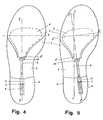
- fig. 5 shows the same shoe seen from below and whose pushing device acts in the direction of the longitudinal axis of the shoe
- fig. 5 shows the same shoe seen from below and whose pushing device acts in an oblique direction relative to the longitudinal axis.
- Its basic constitution includes a shoe of substantially usual shape and structure, where on the lower part of the sole 1 is applied a metal blade 2, thin but robust, flexible and elastic, the part closest to the tip of the shoe is fixed, using known means, to the sole 1, while the other part, which is conveniently restricted towards the end, is free and therefore capable of detaching from the sole under the effect of a force lateral thrust directed downwards and applied at its end; a sub-sole 3 having the function of covering the face of the blade 2 directed towards the ground and of forming a non-slip surface; of a pushing device of said blade 2 comprising at least: a compression type spring 4, housed in a tube 5 fixed in the heel 6, this spring 4 transmitting its compression action to the blade 2 via a piston 7 and a connecting rod 8 shaped so that it is hidden under the central arch 9 of the shoe and connected at one end directly to the piston 7 and by the other at the end 2 'of the blade 2 by means of a hinge 22.
- a compression type spring 4 housed in a tube 5 fixed
- said spring 4 has adequate dimensions in relation to the thrust that it is desired to obtain and that it is variable depending on the infirmity and the weight of the person wearing the shoe.
- the force F1 with which the spring 4 in extension acts on the blade 2 has a component F2 in the free end 2 'of the blade, which component F2 is transverse or oblique to the blade and directed downwards: this determines the uplift of the tip of the shoe.
- the longitudinal axis of the spring 4 and of the link 8 is either in a plane which has the longitudinal axis YY of the shoe as its outline (example illustrated in FIG. 4), so that the toe of the shoe undergoes a simple lifting by rotation around the trans axis versal XX; either in a plane parallel to it or else oblique (example illustrated in fig. 5) so that the toe of the shoe undergoes a lifting with torsion by effect of the rotation around the axis X'X '.
- the blade part 2 intended to be fixed to the sole 1 has a variable width extension in order to be extended over the entire width of the sole or else on a part which may be central or lateral with respect to the sole.
Description
L'invention concerne une chaussure orthopédique; une lame métallique fine, flexible et élastique est prévue sous la semelle avec la partie la plus proche de la pointe de la chaussure fixée à la semelle et celle la plus proche du talon, libre par rapport de la semelle mais reliée à un dispositif de poussée vers la pointe de la chaussure, dissimulé dans le talon; la force appliquée à la libre extrémité de la lame a un effect actif dirigé vers le sol qui provoque le soulèvement de la pointe de la chaussure lorsque le pied est soulevé de terre.The invention relates to an orthopedic shoe; a thin, flexible and elastic metal blade is provided under the sole with the part closest to the toe of the shoe fixed to the sole and that closest to the heel, free relative to the sole but connected to a pushing device towards the tip of the shoe, hidden in the heel; the force applied to the free end of the blade has an active effect directed towards the ground which causes the tip of the shoe to rise when the foot is lifted from the ground.
On sait que, pendant la locomotion, les membres inférieurs du corps humain sont tous deux actifs et, pendant que l'un, s'appuyant sur le sol, soutient le poids du corps et pousse en avant et vers le haut son centre de gravité, l'autre se raccourcit pour accomplir un mouvement pendulaire et se porter en avant; à ceci coopèrent les muscles fléchisseurs de la cuisse ainsi que les groupes musculaires qui, plus précisément, agissent sur le pied pour son extension.It is known that, during locomotion, the lower limbs of the human body are both active and, while one, leaning on the ground, supports the weight of the body and pushes its center of gravity forward and upwards , the other shortens to accomplish a pendulum movement and to move forward; to this cooperate the flexor muscles of the thigh as well as the muscular groups which, more precisely, act on the foot for its extension.
Quand cette dite extension fait défaut ou est insuffisante comme, par exemple, chez les hémiplégiques, paraplégiques, handicapés moteur et sujets à paralysies flasques ou autres infirmités ou malformations des membres inférieurs, on constate, pendant la progression, que la pointe du pied frotte par terre, ce qui est la cause de fréquentes chutes. La présente invention a pour but de proposer un remède à la difficulté de déambulation de ces sujets.When this said extension is lacking or is insufficient such as, for example, in hemiplegics, paraplegics, motor handicapped and subjects with flaccid paralysis or other infirmities or malformations of the lower limbs, it is noted, during the progression, that the tip of the foot rubs by earth, which is the cause of frequent falls. The object of the present invention is to propose a remedy for the difficulty of wandering these subjects.
Il est connu par le brevet GB 525 963 une chaussure pourvu d'une lame métallique, élastique, placée par une de ses extrémités rigidement dans le talon et, par son autre extrémité, au contact ou rattachée à l'arrière de la semelle de la chaussure. Mais ladite lame métallique a le seul but d'aider au fonctionnement de la chaussure, c'est-a-dire de rendre la déambulation moins fatigante à qui a bon pied; elle ne sert pas à celui qui à un pied paralysé ou malformé, étant donné qu'elle n'est pas une chaussure orthopédique et ne permet pas l'érection automatique de la pointe de la chaussure alors que le pied est soulevé de terre, pour être porté en avant.GB 525 963 discloses a shoe provided with an elastic metal blade placed by one of its ends rigidly in the heel and, by its other end, in contact with or attached to the rear of the sole of the shoe. But said metal blade has the sole purpose of helping the functioning of the shoe, that is to say making walking less tiring for those who have good foot; it is not used for those who have a paralyzed or malformed foot, since it is not an orthopedic shoe and does not allow the automatic erection of the tip of the shoe when the foot is lifted from the ground, to be carried forward.
Cette invention, telle qu'elle est caractérisée dans les revendications, résoud le problème, consistant à provoquer le soulévement automatique de la pointe de la chaussure alors que le pied de celui qui la chausse est dégagé du poids du corps et doit, pendant la locomotion, être porté en avant.This invention, as characterized in the claims, solves the problem of inducing the automatic lifting of the toe of the shoe while the foot of the wearer is released from the weight of the body and must, during the locomotion , be carried forward.
Ceci est obtenu à l'aide d'une lame résistante, flé- xible et élastique, se situant sous la semelle, dont la partie la plus proche de la pointe de la chaussure est fixée à la semelle et celle la plus lointaine est libre et reliée à un dispositif de poussée vers la pointe de la chaussure, dissimulé dans le talon.This is obtained using a resistant, flexible and elastic blade, located under the sole, the part closest to the toe of the shoe is fixed to the sole and the most distant part is free and connected to a pushing device towards the tip of the shoe, hidden in the heel.
Les avantages obtenus grâce à cette invention consistent en ceci que la pointe de la chaussure est soulevée automatiquement chaque fois que la chaussure est dégagée du poids du corps; que le dit soulèvement peut concerner toute la largeur de la semelle ou, d'une façon préeminante, seulement une moitié, en fonction de l'infirmité du pied du porteur; que le soulèvement peut comporter aussi une torsion de la semelle, ce qui est d'une grande utilité en cas de pieds équins, varus ou avec supination.The advantages obtained thanks to this invention consist in that the toe of the shoe is lifted automatically each time the shoe is released from the weight of the body; that said lifting may concern the entire width of the sole or, pre-eminently, only half, depending on the infirmity of the wearer's foot; that the lifting can also include a twisting of the sole, which is of great use in the case of equine, varus or supine feet.
Dans ce qui suit l'invention est exposée plus en détail et à l'aide des dessins en annexe, représentant seulement un mode d'exécution.In what follows the invention is explained in more detail and with the aid of the appended drawings, representing only one embodiment.
La fig. 1 représente la vue d'ensemble d'une chaussure droite conforme à l'invention, en position de non-utilisation;Fig. 1 shows the overall view of a straight shoe according to the invention, in the non-use position;
la fig. 2 représente la même chaussure en position d'utilisation avec le pied chargé du poids du corps;fig. 2 shows the same shoe in the position of use with the foot loaded with the weight of the body;
la fig. 3 représente la même chaussure en position d'utilisation avec le pied dégagé du poids du corps comme pendant la phase d'avancement pour la déambulation;fig. 3 shows the same shoe in the position of use with the foot released from the weight of the body as during the advancement phase for walking;
la fig. 5 représente la même chaussure vue de dessous et dont le dispositif de poussée agit en direction de l'axe longitudinal de la chaussure;fig. 5 shows the same shoe seen from below and whose pushing device acts in the direction of the longitudinal axis of the shoe;
la fig. 5 représente la même chaussure vue de dessous et dont le dispositif de poussée agit en direction oblique par rapport à l'axe longitudinal.fig. 5 shows the same shoe seen from below and whose pushing device acts in an oblique direction relative to the longitudinal axis.
Sa constitution de base comprend une chaussure de forme et structure substantiellement usuelles, où sur la partie inférieure de la semelle 1 est appliquée une lame 2 métallique, fine mais robuste, flexible et élastique dont la partie la plus proche de la pointe de la chaussure est fixée, à l'aide de moyens connus, à la semelle 1, alors que l'autre partie, qui est opportunément restreinte vers l'extrémité, est libre et donc susceptible de se détacher de la semelle sous l'effet d'une force de poussée latérale dirigée vers le bas et appliquée à son extrémité; d'une sous-semelle 3 ayant la fonction de couvrir la face de la lame 2 dirigée vers le sol et de former une surface antidérapante; d'un dispositif de poussée de la dite lame 2 comprenant au moins: un ressort 4 de type à compression, logé dans un tube 5 fixé dans le talon 6, ce ressort 4 transmettant son action de compression à la lame 2 par l'intermédiaire d'un piston 7 et d'une biellette 8 profilée de telle façon qu'elle est dissimulée sous la voûte centrale 9 de la chaussure et reliée par une extrémité directement au piston 7 et par l'autre à l'extrémité 2' de la lame 2 au moyen d'un charnière 22.Its basic constitution includes a shoe of substantially usual shape and structure, where on the lower part of the sole 1 is applied a
Il va de soi que le dit ressort 4 a des dimensions adéquates en relation à la poussée que l'on veut obtenir et qu'il est variable en fonction de l'infirmité et du poids de celui qui porte la chaussure.It goes without saying that said
Avec le pied soulevé de terre et donc dégagé, la force F1 avec laquelle le ressort 4 en extension agit sur la lame 2 a une composante F2 dans l'extrémité libre 2' de la lame, laquelle composante F2 est transversale ou oblique à la lame et dirigée vers le bas: ceci détermine le soulèvement de la pointe de la chaussure.With the foot raised from the ground and therefore cleared, the force F1 with which the
Au contraire, avec le pied appuyé par terre et chargé du poids P1 du corps, la composante F2 est dirigée vers le haut et le ressort 4 est comprimé dans son logement.On the contrary, with the foot supported on the ground and loaded with the weight P1 of the body, the component F2 is directed upwards and the
L'axe longitudinal du ressort 4 et de la biellette 8 est soit dans un plan qui a pour tracé l'axe longitudinal YY de la chaussure (exemple illustré à la fig. 4), ce qui fait que la pointe de la chaussure subit un simple soulèvement par rotation autour de l'axe transversal XX; soit dans un plan parallèle à celui-ci ou bien oblique (exemple illustré à la fig. 5) ce qui fait que la pointe de la chaussure subit un soulèvement avec torsion par effet de la rotation autour de l'axe X'X'.The longitudinal axis of the
En outre la partie de lame 2 destinée à être fixée à la semelle 1 a une extension variable en largeur afin d'être étendue sur toute la largeur de la semelle ou bien sur une partie qui peut être centrale ou latérale par rapport à la semelle.In addition, the
Claims (5)
Priority Applications (1)
| Application Number | Priority Date | Filing Date | Title |
|---|---|---|---|
| AT80830044T ATE5935T1 (en) | 1979-08-31 | 1980-07-04 | ORTHOPEDIC SHOE WITH AUTOMATICALLY RAISE TOE WHEN LIFTING THE FOOT. |
Applications Claiming Priority (2)
| Application Number | Priority Date | Filing Date | Title |
|---|---|---|---|
| IT952479 | 1979-08-31 | ||
| IT09524/79A IT1203275B (en) | 1979-08-31 | 1979-08-31 | ERECTILE TOE ORTHOPEDIC SHOE AUTOMATICALLY WITH LIFTED FOOT |
Publications (3)
| Publication Number | Publication Date |
|---|---|
| EP0025020A2 EP0025020A2 (en) | 1981-03-11 |
| EP0025020A3 EP0025020A3 (en) | 1981-08-26 |
| EP0025020B1 true EP0025020B1 (en) | 1984-01-25 |
Family
ID=11131582
Family Applications (1)
| Application Number | Title | Priority Date | Filing Date |
|---|---|---|---|
| EP80830044A Expired EP0025020B1 (en) | 1979-08-31 | 1980-07-04 | Orthopaedic shoe with automatically erect toe when the foot is raised |
Country Status (11)
| Country | Link |
|---|---|
| US (1) | US4331152A (en) |
| EP (1) | EP0025020B1 (en) |
| JP (1) | JPS5636946A (en) |
| AR (1) | AR221281A1 (en) |
| AT (1) | ATE5935T1 (en) |
| BR (1) | BR8005408A (en) |
| CA (1) | CA1140338A (en) |
| DE (1) | DE3066270D1 (en) |
| ES (1) | ES252138Y (en) |
| GR (1) | GR69696B (en) |
| IT (1) | IT1203275B (en) |
Families Citing this family (9)
| Publication number | Priority date | Publication date | Assignee | Title |
|---|---|---|---|---|
| US4573457A (en) * | 1983-12-29 | 1986-03-04 | Parks Thomas J | Toe lifting shoe |
| US4941273A (en) * | 1988-11-29 | 1990-07-17 | Converse Inc. | Shoe with an artificial tendon system |
| US8505220B2 (en) | 2010-03-04 | 2013-08-13 | Nike, Inc. | Flex groove sole assembly with biasing structure |
| US9241535B2 (en) | 2013-03-14 | 2016-01-26 | Nike, Inc. | Sole structures and articles incorporating same |
| US9364043B2 (en) * | 2013-06-13 | 2016-06-14 | Nike, Inc. | Article of footwear with sole member |
| AU2016314145B2 (en) | 2015-08-31 | 2021-12-02 | Ronald Frederick SCHUMANN | Shoe sole |
| US11026472B2 (en) | 2016-07-22 | 2021-06-08 | Nike, Inc. | Dynamic lacing system |
| CN106726049A (en) * | 2017-01-22 | 2017-05-31 | 张钲坪 | One kind digitlization rehabilitation KAFO |
| US11129447B2 (en) | 2018-09-06 | 2021-09-28 | Nike, Inc. | Dynamic lacing system with feedback mechanism |
Family Cites Families (5)
| Publication number | Priority date | Publication date | Assignee | Title |
|---|---|---|---|---|
| DE106810C (en) * | ||||
| DE358247C (en) * | 1922-09-07 | Wilhelm Betz | Apparatus to remedy foot paralysis | |
| DE397582C (en) * | 1922-08-04 | 1924-06-26 | Arthur Brebeck | Metal bracket with longitudinal stiffening bulge that can be attached to the heel and joint of the shoe |
| GB525963A (en) * | 1939-03-01 | 1940-09-09 | Walter Miller Metcalf | Improvements in devices to support the feet of a pedestrian and to facilitate walking |
| US3585993A (en) * | 1969-07-22 | 1971-06-22 | Aljie Heedly | Toe lift device for a dropped foot |
-
1979
- 1979-08-31 IT IT09524/79A patent/IT1203275B/en active
-
1980
- 1980-07-04 EP EP80830044A patent/EP0025020B1/en not_active Expired
- 1980-07-04 AT AT80830044T patent/ATE5935T1/en not_active IP Right Cessation
- 1980-07-04 DE DE8080830044T patent/DE3066270D1/en not_active Expired
- 1980-07-18 ES ES1980252138U patent/ES252138Y/en not_active Expired
- 1980-08-13 AR AR282138A patent/AR221281A1/en active
- 1980-08-27 BR BR8005408A patent/BR8005408A/en unknown
- 1980-08-27 JP JP11717380A patent/JPS5636946A/en active Pending
- 1980-08-29 CA CA000359357A patent/CA1140338A/en not_active Expired
- 1980-08-29 GR GR62771A patent/GR69696B/el unknown
- 1980-09-02 US US06/183,438 patent/US4331152A/en not_active Expired - Lifetime
Also Published As
| Publication number | Publication date |
|---|---|
| BR8005408A (en) | 1981-03-10 |
| JPS5636946A (en) | 1981-04-10 |
| CA1140338A (en) | 1983-02-01 |
| IT7909524A0 (en) | 1979-08-31 |
| US4331152A (en) | 1982-05-25 |
| IT1203275B (en) | 1989-02-15 |
| EP0025020A2 (en) | 1981-03-11 |
| ATE5935T1 (en) | 1984-02-15 |
| DE3066270D1 (en) | 1984-03-01 |
| ES252138U (en) | 1980-11-01 |
| ES252138Y (en) | 1981-04-16 |
| AR221281A1 (en) | 1981-01-15 |
| GR69696B (en) | 1982-07-08 |
| EP0025020A3 (en) | 1981-08-26 |
Similar Documents
| Publication | Publication Date | Title |
|---|---|---|
| EP0422167B1 (en) | Orthopedic apparatus for persons handicapped in one leg | |
| JP2887417B2 (en) | Walking aids | |
| EP0025020B1 (en) | Orthopaedic shoe with automatically erect toe when the foot is raised | |
| JP2007503867A (en) | Artificial leg | |
| CA2340076C (en) | Ski pole | |
| EP0797936A1 (en) | Retaining device for a shoe on a board with a hinged dorsal support | |
| FR2535604A1 (en) | EXTERNAL APPARATUS FOR DISABLED MOTORS OF AT LEAST ONE TOP MEMBER | |
| US20040226593A1 (en) | Walking cane | |
| EP2621340A1 (en) | Apparatus for closed kinetic chain muscle strengthening and/or rehabilitation of the shoulder joint and of the upper limb | |
| FR2779659A1 (en) | Double-articulating device for boot to ski attachment | |
| EP3490517B1 (en) | Exoskeleton structure that provides force assistance to the user | |
| FR2600901A1 (en) | SECURITY FIXING OF A SHOE ON A SKI | |
| CN204950770U (en) | Plug dock toilet bowl cushion turner and fixing base | |
| WO2002045631A1 (en) | Lumbar support device | |
| EP0664141B1 (en) | Helping device for foot movement | |
| WO1985005268A1 (en) | Articulated walking aid device | |
| FR2601585A1 (en) | Device promoting rectal evacuation | |
| FR2825930A1 (en) | Snowshoe comprises mesh with front central hole and boot retaining device and intermediate part comprising movable front wall occupying hole and end coupling tooth | |
| FR2913880A1 (en) | Orthopedic apparatus for lower-limb handicapped person, has connection elements that undergo wide range of movement independent of support element to assure partial disassociation of balancing function and dimension of perimeter of base | |
| CH681201A5 (en) | Orthopaedic support for person handicapped in one leg | |
| FR2782648A1 (en) | Posture device for ankle and foot for bending, internal and external rotation, torsion and pulling of leg and foot muscles; has main piece with stop for heel and inclined plane to support foot | |
| FR3086533A1 (en) | SELF-STRETCHING DEVICE FOR RELIEVING AND / OR PREVENTING DORSO-LUMBAR PAIN OF A USER | |
| FR2516761A1 (en) | ORTHOPEDIC DEVICE FOR REPORTING INTO A BOOT OR SHOE AND FOR HOLDING THE FOOT | |
| WO2021229196A1 (en) | Hands-free crutch comprising means for limiting the angular movement of a leg plate relative to a brace | |
| CH445349A (en) | Orthopedic device |
Legal Events
| Date | Code | Title | Description |
|---|---|---|---|
| PUAI | Public reference made under article 153(3) epc to a published international application that has entered the european phase |
Free format text: ORIGINAL CODE: 0009012 |
|
| AK | Designated contracting states |
Designated state(s): AT BE CH DE FR GB LU NL SE |
|
| PUAL | Search report despatched |
Free format text: ORIGINAL CODE: 0009013 |
|
| AK | Designated contracting states |
Designated state(s): AT BE CH DE FR GB LU NL SE |
|
| 17P | Request for examination filed |
Effective date: 19810908 |
|
| GRAA | (expected) grant |
Free format text: ORIGINAL CODE: 0009210 |
|
| AK | Designated contracting states |
Designated state(s): AT BE CH DE FR GB LI LU NL SE |
|
| PG25 | Lapsed in a contracting state [announced via postgrant information from national office to epo] |
Ref country code: NL Effective date: 19840125 |
|
| REF | Corresponds to: |
Ref document number: 5935 Country of ref document: AT Date of ref document: 19840215 Kind code of ref document: T |
|
| REF | Corresponds to: |
Ref document number: 3066270 Country of ref document: DE Date of ref document: 19840301 |
|
| NLV1 | Nl: lapsed or annulled due to failure to fulfill the requirements of art. 29p and 29m of the patents act | ||
| PG25 | Lapsed in a contracting state [announced via postgrant information from national office to epo] |
Ref country code: AT Effective date: 19840704 |
|
| PG25 | Lapsed in a contracting state [announced via postgrant information from national office to epo] |
Ref country code: SE Effective date: 19840705 |
|
| PG25 | Lapsed in a contracting state [announced via postgrant information from national office to epo] |
Ref country code: LU Free format text: LAPSE BECAUSE OF NON-PAYMENT OF DUE FEES Effective date: 19840731 Ref country code: LI Effective date: 19840731 Ref country code: CH Effective date: 19840731 Ref country code: BE Effective date: 19840731 |
|
| PLBE | No opposition filed within time limit |
Free format text: ORIGINAL CODE: 0009261 |
|
| STAA | Information on the status of an ep patent application or granted ep patent |
Free format text: STATUS: NO OPPOSITION FILED WITHIN TIME LIMIT |
|
| 26N | No opposition filed | ||
| BERE | Be: lapsed |
Owner name: CALZATURIFICIO TIGER S.R.L. Effective date: 19840704 |
|
| GBPC | Gb: european patent ceased through non-payment of renewal fee | ||
| PG25 | Lapsed in a contracting state [announced via postgrant information from national office to epo] |
Ref country code: FR Free format text: LAPSE BECAUSE OF NON-PAYMENT OF DUE FEES Effective date: 19850329 |
|
| REG | Reference to a national code |
Ref country code: CH Ref legal event code: PL |
|
| PG25 | Lapsed in a contracting state [announced via postgrant information from national office to epo] |
Ref country code: DE Effective date: 19850402 |
|
| REG | Reference to a national code |
Ref country code: FR Ref legal event code: ST |
|
| PG25 | Lapsed in a contracting state [announced via postgrant information from national office to epo] |
Ref country code: GB Effective date: 19881118 |
|
| EUG | Se: european patent has lapsed |
Ref document number: 80830044.6 Effective date: 19850617 |