EP0024350B1 - Kursanzeiger - Google Patents
Kursanzeiger Download PDFInfo
- Publication number
- EP0024350B1 EP0024350B1 EP80104836A EP80104836A EP0024350B1 EP 0024350 B1 EP0024350 B1 EP 0024350B1 EP 80104836 A EP80104836 A EP 80104836A EP 80104836 A EP80104836 A EP 80104836A EP 0024350 B1 EP0024350 B1 EP 0024350B1
- Authority
- EP
- European Patent Office
- Prior art keywords
- gyroscope
- axis
- amplifier
- vertical axis
- gyro
- Prior art date
- Legal status (The legal status is an assumption and is not a legal conclusion. Google has not performed a legal analysis and makes no representation as to the accuracy of the status listed.)
- Expired
Links
- 238000002955 isolation Methods 0.000 claims description 6
- 230000035945 sensitivity Effects 0.000 description 9
- 230000005284 excitation Effects 0.000 description 4
- 238000010079 rubber tapping Methods 0.000 description 3
- 230000005484 gravity Effects 0.000 description 2
- 230000033228 biological regulation Effects 0.000 description 1
- 239000003990 capacitor Substances 0.000 description 1
- 230000008878 coupling Effects 0.000 description 1
- 238000010168 coupling process Methods 0.000 description 1
- 238000005859 coupling reaction Methods 0.000 description 1
- 239000013078 crystal Substances 0.000 description 1
- 238000010586 diagram Methods 0.000 description 1
- 238000001914 filtration Methods 0.000 description 1
- 230000010354 integration Effects 0.000 description 1
- 238000005259 measurement Methods 0.000 description 1
- 238000000034 method Methods 0.000 description 1
- 230000001629 suppression Effects 0.000 description 1
- 239000000725 suspension Substances 0.000 description 1
- 230000001360 synchronised effect Effects 0.000 description 1
- 230000007704 transition Effects 0.000 description 1
- 238000004804 winding Methods 0.000 description 1
Images
Classifications
-
- G—PHYSICS
- G01—MEASURING; TESTING
- G01C—MEASURING DISTANCES, LEVELS OR BEARINGS; SURVEYING; NAVIGATION; GYROSCOPIC INSTRUMENTS; PHOTOGRAMMETRY OR VIDEOGRAMMETRY
- G01C19/00—Gyroscopes; Turn-sensitive devices using vibrating masses; Turn-sensitive devices without moving masses; Measuring angular rate using gyroscopic effects
- G01C19/02—Rotary gyroscopes
- G01C19/34—Rotary gyroscopes for indicating a direction in the horizontal plane, e.g. directional gyroscopes
- G01C19/38—Rotary gyroscopes for indicating a direction in the horizontal plane, e.g. directional gyroscopes with north-seeking action by other than magnetic means, e.g. gyrocompasses using earth's rotation
Definitions
- the invention relates to a course indicator, especially for tanks, of the type specified in the preamble of claim 1.
- Such course indicators are known (DE-A-1 548 467). It is a directional gyro with gimbal suspension in a two-frame system and a tap, which measures deviations of the running axis from the horizontal, with torque generators being arranged on both the middle and the outer gimbal axis, which are controlled by the signal supplied by the tap via amplifiers .
- the torque generator located on the center gimbal axis can be switched on and off alternatively in order to work as a north-looking gyro or as a course gyro.
- the invention has for its object to provide a course indicator of the type specified in the preamble of claim 1, which is further simplified, in particular makes a servo mechanism for coupling the gyro output with a readable course display device superfluous.
- the course indicator according to the invention has a platform with one degree of freedom, which is stabilized by a gyroscope with three degrees of freedom and two sensitivity axes.
- a circuit is provided to initially align the gyro to the true north in gyrocompass alignment mode, after which it serves as a course gyro.
- one of the sensitivity axes of the gyro is coupled via an amplifier to a torque generator assigned to this sensitivity axis and can be coupled via a further amplifier to a torque generator assigned to the other sensitivity axis, while the other sensitivity axis of the gyro is coupled via an additional amplifier to a torque generator assigned to the platform is.
- the amplifier between the first-mentioned sensitivity axis of the gyro and the torque generator assigned to the other sensitivity axis is operated by the gyro-speed tether current as a direct north measurement during gyro-compass alignment operation of the course indicator.
- a frustoconical compass card is attached to the platform or at the top of the gyro housing connected to it, so that immediate gyro course information is guaranteed.
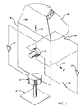
- the platform 1 has a base 6 which carries a platform 10 with one degree of freedom.
- the platform 10 is rotatably mounted about a vertical axis and stabilized by a gyroscope 11 with three degrees of freedom, which is oriented so that its two sensitivity axes extend along the east axis 12 or the azimuth or vertical axis 13.
- the dry gyroscope 11 has a housing, a rotor which can be tilted about each of the two sensitivity axes or both about the east axis 12 and about the vertical axis 13 and a motor which keeps the rotor in circulation at a predetermined speed .
- the housing is attached to or formed with an azimuth or course frame 14 and connected to the platform 10 by the course frame 14.
- a 45 ° frusto-conical compass map 16 is attached directly to the course frame 14 to indicate the course, so that a servo mechanism is superfluous and the respective course display is visible both when the course indicator is viewed vertically from above and when the course indicator is viewed horizontally from the side.
- the gyroscope 11 also has an east axis tap 19 for detecting the relative rotation of the housing about the east axis 12, an east axis torque generator 20 for adjusting the rotor about the east axis 12, and a vertical axis tap 21 for detecting the relative rotation of the housing around the vertical axis 13 and a vertical axis torque generator 22 for moving the rotor about the vertical axis 13.
- a course frame torque generator 23 serves to rotate the platform 10 and the course frame 14 attached thereto with the housing of the gyro 11 about the vertical axis 13.
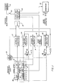
- the east-axis tap 19 is coupled to the east-axis torque generator 20 via an east-axis speed restraint amplifier 24, which continues to act upon the vertical-axis torque generator 22 via a gyro-compass amplifier 25.
- a relay 26 is provided between the gyro compass amplifier 25 and the vertical axis torque generator 22.
- the vertical axis tap 21 is coupled to the course frame torque generator 23 by means of a vertical axis isolating amplifier 27 so that the course frame torque generator 23 moves the course frame 14 to keep it aligned with the rotor of the gyro 11.
- a clock and countdown circuit 30 is connected to a tapping excitation circuit 31 the.
- the clock and countdown circuit 30 has a crystal oscillator clock which supplies a diode transistor logic level square-wave voltage, and also countdown logic which produces a square-wave voltage for the tapping excitation circuit 31 with the aid of the clock input signal.
- This is an amplifier that uses the logic input signal to provide a stable sine wave with little distortion, which is achieved by combined filtering and feedback.
- the electrical output signal of the vertical axis tap 21 is amplified by the vertical axis isolating amplifier 27, the electrical output signal of which drives the course frame torque generator 23.
- the vertical axis isolation amplifier 27 contains a proportional gain channel and a parallel integral channel in order to achieve total servo loop compensation with sufficient gain and phase tolerance.
- the two signals are summed in an operational amplifier, the output of which drives an H-bridge output circuit with the cage frame torque generator 23 as a load, with a relay connected in series with the cage frame torque generator 23 being used to start the vertical axis isolation loop close, further open it when a built-in test circuit 36 detects a fault.
- the built-in test circuit 36 checks the vertical axis isolating loop, which comprises the vertical axis tap 21, the vertical axis isolating amplifier 27 and the course frame torque generator 23, and the gyrocompass loop, which comprises the eastern axis tap 19, the eastern axis speed capturing amplifier 24, the gyrocompass amplifier 25 and the vertical axis torque generator 22.
- the built-in test circuit 36 is turned on when the system's initial power on and settle has stopped. Normally, both the vertical axis cut-off loop and the gyro-compass loop are always in the zero state.
- the built-in test circuit 36 issues an error warning.
- a large signal for example approximately 10 volts DC voltage
- the relay in series with the course frame torque generator 23 is opened, as mentioned.
- the electrical output signal of the east axis tap 19 is fed to the east axis speed capturing amplifier 24, which in a known manner has an alternating voltage preamplifier and a synchronous demodulator, which is coupled to the preamplifier for quadrature suppression. Operational amplifiers for integration and loop servo compensation are also provided.
- the next stage has a notch filter with an operational amplifier and resistors as well as capacitors in a parallel T circuit to achieve high attenuation.
- the output stage of this loop is designed as a current amplifier with feedback from a resistor connected in series with the east axis torque generator 20. The loop gain is changed by shunting a load resistor in series with the east axis torque generator 20.
- the electrical output signal of the east axis velocity capturing amplifier 24 goes to the gyro amplifier 25 to feed a power summing amplifier in a current feedback circuit in gyro compass alignment operation.
- the main input of the summing amplifier is grounded, while a correction signal of azimuth or high-axis gyroscopic compensation can be input to the summing amplifier.
- Low drift operational amplifiers are used in this circuit to achieve the desired system accuracy.
- the electrical output signal of the gyro compass amplifier 25 goes via the relay 26 to the vertical axis torque generator 22, which rotates the rotor of the gyro 11 about the vertical axis 13.
- the electrical output signal of the gyro compass amplifier 25 is supplied to the built-in test circuit 36 in order to monitor it in the manner described, just like the electrical output signal of the vertical axis isolating amplifier 27.
- the clock and countdown circuit 30 is also connected to a rotor drive feed circuit 45 which counts down the logic signal from the clock and countdown circuit 30 to generate an input signal for a countdown logic which produces four phases for the input signal of the rotor drive feed circuit 45.
- the latter contains two H transition bridges, which are separated by the
- Rotor drive feed circuit input logic signals are driven.
- the rotor drive feed circuit 45 is coupled to the motor of the gyro 11, each phase winding of the motor being the load for the two H-bridges.
- the H-bridges are excited by a single-ended DC voltage.
- the input logic is equipped with a frequency detector circuit to detect signal losses and prevent damage to the motor.
- the clock and countdown circuit 30 finally delivers a slip sync signal which is fed to a sequential circuit 50.
- the control signal at time T o closes one Switch 52 so that the clock and countdown circuit 30 is activated and the gyro 11 is energized.
- An energy source 53 charged with a 28 volt DC battery voltage works with pulse duration modulation for regulation and power purposes.
- the earth's rotational speed W e can be broken down into a horizontal component W h and a vertical component W v , which are in a plane perpendicular to the direction of the local gravity or in the direction containing the local direction of gravity, in the north / south direction aligned level.
- the east axis 12 of the dry gyroscope 11 with three degrees of freedom and a cardanic flexure attached to the course frame 14 is tied back to itself via the east axis speed restraint amplifier 24, while the vertical axis 13 of the gyroscope 11 is connected to the platform 10 via the vertical axis isolating amplifier 27 is tied up.
- the east axis speed control amplifier 24 binds the rotor to the housing of the gyro 11 about the east axis 12, the vertical axis isolating amplifier 27 binds the housing to the rotor of the gyro 11 about the vertical axis 13.
- the course reference system is not yet in able to provide a north reference because the east axis 12 of the gyroscope 11 is not aligned with its reference point, namely east.
- the east axis tap 19 detects a component W h - sin ⁇ in the horizontal earth rotation speed Wh.
- the housing of the gyro 11 rotates about the rotor's east axis 12 at this speed, and the east axis speed lock amplifier 24 outputs an electrical output signal to the east axis torque generator 20 to move the rotor so that it follows the housing and the east axis.
- Tap 19 is kept at zero.
- An equivalent of the signal for the east axis torque generator 20 of the gyro 11 is amplified and fed to the gyro compass amplifier 25, the electrical output signal of which is sent to the vertical axis torque generator 22, which adjusts the rotor with respect to the housing of the gyro 11 about the vertical axis 13.
- Any relative movement between the rotor of the gyro 11 and its housing, including the course frame 14, is detected by the vertical axis tap 21, which emits a corresponding electrical output signal, which is processed by means of the vertical axis isolating amplifier 27, around the course frame torque generator 23 to drive that the course frame 14 follows the runner and the vertical axis tap 21 is kept at zero.
- the direction of rotation of the course frame 14 is such that the angle V is reduced.
- the gyro compass alignment mode ends and the system switches to course gyro mode.
- the gyro compass loop between the east axis speed control amplifier 24 and the vertical axis torque generator 22 is opened by means of the relay 26, specifically by the sequential circuit 50 or by hand.
- the course gyro mode serves to maintain the alignment during the travel of the vehicle provided with the course indicator, which was obtained in the gyrocompass alignment mode. This is accomplished with the help of the electronics described (east axis speed control amplifier 24 and vertical axis isolation amplifier 27).
- the east axis speed restraint amplifier 24 protects the rotor of the gyro 11 from disturbances by the rotor being acted upon in such a way that it can follow the course frame 14 with all movements of the base 6 which the vehicle causes.
- the vertical axis 13 keeps the north orientation. Any vehicle movement about the vertical axis 13, which could disturb the course frame 14, is detected by the vertical axis tap 21, the electrical output signal of which acts on the course frame torque generator 23 around the course frame 14 to be tied to the fixed rotor of the roundabout 11, which provides the north reference.
Landscapes
- Engineering & Computer Science (AREA)
- Remote Sensing (AREA)
- Radar, Positioning & Navigation (AREA)
- General Physics & Mathematics (AREA)
- Physics & Mathematics (AREA)
- Geology (AREA)
- Life Sciences & Earth Sciences (AREA)
- General Life Sciences & Earth Sciences (AREA)
- Environmental & Geological Engineering (AREA)
- Gyroscopes (AREA)
- Luminescent Compositions (AREA)
- Lubrication Of Internal Combustion Engines (AREA)
- Road Signs Or Road Markings (AREA)
Applications Claiming Priority (2)
| Application Number | Priority Date | Filing Date | Title |
|---|---|---|---|
| US66702 | 1979-08-15 | ||
| US06/066,702 US4599803A (en) | 1979-08-15 | 1979-08-15 | Heading indicator and method of using |
Publications (2)
| Publication Number | Publication Date |
|---|---|
| EP0024350A1 EP0024350A1 (de) | 1981-03-04 |
| EP0024350B1 true EP0024350B1 (de) | 1983-03-23 |
Family
ID=22071151
Family Applications (1)
| Application Number | Title | Priority Date | Filing Date |
|---|---|---|---|
| EP80104836A Expired EP0024350B1 (de) | 1979-08-15 | 1980-08-14 | Kursanzeiger |
Country Status (7)
| Country | Link |
|---|---|
| US (1) | US4599803A (enExample) |
| EP (1) | EP0024350B1 (enExample) |
| JP (1) | JPS5630607A (enExample) |
| CA (1) | CA1146781A (enExample) |
| DE (1) | DE3062440D1 (enExample) |
| IL (1) | IL60515A (enExample) |
| NO (1) | NO157356C (enExample) |
Families Citing this family (2)
| Publication number | Priority date | Publication date | Assignee | Title |
|---|---|---|---|---|
| DE3136703C1 (de) * | 1981-09-16 | 1982-11-04 | M.A.N.- Roland Druckmaschinen AG, 6050 Offenbach | Einrichtungen an Druckmaschinen mit Registerverstelleinrichtungen |
| US5430342A (en) * | 1993-04-27 | 1995-07-04 | Watson Industries, Inc. | Single bar type vibrating element angular rate sensor system |
Family Cites Families (11)
| Publication number | Priority date | Publication date | Assignee | Title |
|---|---|---|---|---|
| DE1282300B (de) * | 1960-11-17 | 1968-11-07 | North American Aviation Inc | Landkompass |
| US3254419A (en) * | 1962-10-31 | 1966-06-07 | Bendix Corp | Gyroscopic compass system |
| DE1258123B (de) * | 1964-08-29 | 1968-01-04 | Teldix Luftfahrt Ausruestung | Richtungsuchende und richtunghaltende Kreiselvorrichtung |
| US3354726A (en) * | 1965-09-02 | 1967-11-28 | Gen Precision Inc | Two-axis gyro |
| GB1176228A (en) * | 1966-04-04 | 1970-01-01 | Tokyo Keiki Seizosho Company L | Improvements in or relating to Gyrocompasses |
| DE1548467A1 (de) * | 1966-11-29 | 1969-11-20 | Licentia Gmbh | Richtungskreisel |
| US3619906A (en) * | 1969-05-05 | 1971-11-16 | Us Army | Oscillating north-seeking platform |
| US3739480A (en) * | 1970-03-30 | 1973-06-19 | Bendix Corp | Gyro compassing apparatus and method |
| DE2263338C3 (de) * | 1972-12-23 | 1979-10-25 | Teldix Gmbh, 6900 Heidelberg | Nordsuchender Kreisel |
| FR2260083A1 (en) * | 1974-01-31 | 1975-08-29 | Ass Ouvriers Instr Precision | Gyrocompass with rapid north seeking action - has detector signals applied to control motors for ring |
| DE2627037C3 (de) * | 1976-06-16 | 1979-04-05 | Anschuetz & Co Gmbh, 2300 Kiel | Kreiselkompaß |
-
1979
- 1979-08-15 US US06/066,702 patent/US4599803A/en not_active Expired - Lifetime
-
1980
- 1980-07-02 CA CA000355241A patent/CA1146781A/en not_active Expired
- 1980-07-07 IL IL60515A patent/IL60515A/xx unknown
- 1980-07-21 JP JP9975180A patent/JPS5630607A/ja active Granted
- 1980-08-14 NO NO802437A patent/NO157356C/no unknown
- 1980-08-14 DE DE8080104836T patent/DE3062440D1/de not_active Expired
- 1980-08-14 EP EP80104836A patent/EP0024350B1/de not_active Expired
Also Published As
| Publication number | Publication date |
|---|---|
| NO802437L (no) | 1981-02-16 |
| JPS6341403B2 (enExample) | 1988-08-17 |
| IL60515A (en) | 1984-10-31 |
| JPS5630607A (en) | 1981-03-27 |
| NO157356C (no) | 1988-03-02 |
| US4599803A (en) | 1986-07-15 |
| DE3062440D1 (en) | 1983-04-28 |
| NO157356B (no) | 1987-11-23 |
| CA1146781A (en) | 1983-05-24 |
| EP0024350A1 (de) | 1981-03-04 |
Similar Documents
| Publication | Publication Date | Title |
|---|---|---|
| DE3436839C2 (de) | Lenkprozessor | |
| DE2849633C2 (de) | Vorrichtung zum Messen von Azimut und Neigung eines Bohrlochs | |
| DE2504824A1 (de) | Kreisel-bezugsplattform | |
| DE2263338C3 (de) | Nordsuchender Kreisel | |
| DE2545025B2 (de) | Navigationsgerät zur Navigation von Landfahrzeugen | |
| EP0048212B1 (de) | Kurs-Lage-Referenzgerät mit Kreisel | |
| EP0024350B1 (de) | Kursanzeiger | |
| EP0335116A2 (de) | Verfahren zur Ausrichtung einer zweiachsigen Plattform | |
| DE1548517B2 (de) | Kreiselstabilisierte, mit Freiheit um mindestens eine Drehachse gelagerte Plattform | |
| EP0106066B1 (de) | Gerät zur Bestimmung der Nordrichtung | |
| DE3019743A1 (de) | System mit einer plattform mit kardanischer aufhaengung als geraetetraeger in verbindung mit einem fahrzeug und einem inertialsystem | |
| DE2733208A1 (de) | Gyroskopisches instrument | |
| DE2741008A1 (de) | Lageregelungssystem fuer ein raumfahrzeug | |
| DE2157438B2 (de) | Kreiselgesteuerte Stabilisierungseinrichtung | |
| DE3337715C2 (de) | Kurs-Lage-Referenzgerät | |
| DE2160801C3 (de) | Anordnung zur Unterdrückung vorübergehend auftretender Fehler des durch einen Kompaß bestimmten Eigenkurswertes eines Schiffes mit Hilfe eines kardanisch aufgehängten Kurskreisels | |
| DE2158244B2 (de) | Verfahren und Vorrichtung zum Zielhalten für ein auf einer stabilisierten Plattform eines Fahrzeugs angeordnetes Sichtgerät | |
| DE1201074B (de) | Kreiselgeraet fuer Flugzeuge | |
| DE1548436C3 (de) | Trägheitsnavigations-System | |
| DE2649840A1 (de) | Kreiselmagnetkompass-system | |
| DE1773700B2 (de) | Vorrichtung zur Erzeugung einer sehr genauen Bezugsvertikalen an einem von der Navigationsanlage entfernten Ort in einem Flugzeug | |
| DE880549C (de) | Automatisches Steuergerät für Flugzeuge | |
| DE2116885A1 (de) | Richtungskreisel | |
| DE2305663C3 (de) | Kreiselgerät zum Bestimmen der Nordrichtung | |
| DE3029888C2 (enExample) |
Legal Events
| Date | Code | Title | Description |
|---|---|---|---|
| PUAI | Public reference made under article 153(3) epc to a published international application that has entered the european phase |
Free format text: ORIGINAL CODE: 0009012 |
|
| AK | Designated contracting states |
Designated state(s): BE DE FR GB IT NL SE |
|
| ITCL | It: translation for ep claims filed |
Representative=s name: SOCIETA' ITALIANA BREVETTI S.P.A. |
|
| 17P | Request for examination filed |
Effective date: 19810320 |
|
| ITF | It: translation for a ep patent filed | ||
| GRAA | (expected) grant |
Free format text: ORIGINAL CODE: 0009210 |
|
| AK | Designated contracting states |
Designated state(s): BE DE FR GB IT NL SE |
|
| REF | Corresponds to: |
Ref document number: 3062440 Country of ref document: DE Date of ref document: 19830428 |
|
| ET | Fr: translation filed | ||
| PGFP | Annual fee paid to national office [announced via postgrant information from national office to epo] |
Ref country code: DE Payment date: 19840627 Year of fee payment: 5 |
|
| PGFP | Annual fee paid to national office [announced via postgrant information from national office to epo] |
Ref country code: SE Payment date: 19840630 Year of fee payment: 5 |
|
| PGFP | Annual fee paid to national office [announced via postgrant information from national office to epo] |
Ref country code: FR Payment date: 19840702 Year of fee payment: 5 |
|
| PGFP | Annual fee paid to national office [announced via postgrant information from national office to epo] |
Ref country code: BE Payment date: 19840930 Year of fee payment: 5 |
|
| PGFP | Annual fee paid to national office [announced via postgrant information from national office to epo] |
Ref country code: NL Payment date: 19870831 Year of fee payment: 8 |
|
| PG25 | Lapsed in a contracting state [announced via postgrant information from national office to epo] |
Ref country code: GB Effective date: 19890814 |
|
| PG25 | Lapsed in a contracting state [announced via postgrant information from national office to epo] |
Ref country code: SE Effective date: 19890815 |
|
| PG25 | Lapsed in a contracting state [announced via postgrant information from national office to epo] |
Ref country code: BE Effective date: 19890831 |
|
| BERE | Be: lapsed |
Owner name: THE SINGER CY Effective date: 19890831 |
|
| PG25 | Lapsed in a contracting state [announced via postgrant information from national office to epo] |
Ref country code: NL Effective date: 19900301 |
|
| GBPC | Gb: european patent ceased through non-payment of renewal fee | ||
| NLV4 | Nl: lapsed or anulled due to non-payment of the annual fee | ||
| PG25 | Lapsed in a contracting state [announced via postgrant information from national office to epo] |
Ref country code: FR Effective date: 19900427 |
|
| PG25 | Lapsed in a contracting state [announced via postgrant information from national office to epo] |
Ref country code: DE Effective date: 19900501 |
|
| REG | Reference to a national code |
Ref country code: FR Ref legal event code: ST |
|
| EUG | Se: european patent has lapsed |
Ref document number: 80104836.4 Effective date: 19900418 |
|
| PLBE | No opposition filed within time limit |
Free format text: ORIGINAL CODE: 0009261 |
|
| STAA | Information on the status of an ep patent application or granted ep patent |
Free format text: STATUS: NO OPPOSITION FILED WITHIN TIME LIMIT |