EP0023837A1 - Fuel saver for internal combustion engines - Google Patents
Fuel saver for internal combustion engines Download PDFInfo
- Publication number
- EP0023837A1 EP0023837A1 EP80302667A EP80302667A EP0023837A1 EP 0023837 A1 EP0023837 A1 EP 0023837A1 EP 80302667 A EP80302667 A EP 80302667A EP 80302667 A EP80302667 A EP 80302667A EP 0023837 A1 EP0023837 A1 EP 0023837A1
- Authority
- EP
- European Patent Office
- Prior art keywords
- valve
- engine
- vacuum
- mode
- intake manifold
- Prior art date
- Legal status (The legal status is an assumption and is not a legal conclusion. Google has not performed a legal analysis and makes no representation as to the accuracy of the status listed.)
- Withdrawn
Links
- 239000000446 fuel Substances 0.000 title claims abstract description 101
- 238000002485 combustion reaction Methods 0.000 title claims description 7
- 230000001133 acceleration Effects 0.000 claims abstract description 18
- 230000000153 supplemental effect Effects 0.000 claims abstract description 17
- 239000003570 air Substances 0.000 claims description 56
- QSHDDOUJBYECFT-UHFFFAOYSA-N mercury Chemical compound [Hg] QSHDDOUJBYECFT-UHFFFAOYSA-N 0.000 claims description 11
- 229910052753 mercury Inorganic materials 0.000 claims description 11
- 239000012080 ambient air Substances 0.000 claims description 5
- 238000004891 communication Methods 0.000 claims description 5
- 230000008878 coupling Effects 0.000 claims description 3
- 238000010168 coupling process Methods 0.000 claims description 3
- 238000005859 coupling reaction Methods 0.000 claims description 3
- 230000001419 dependent effect Effects 0.000 claims 1
- 239000000203 mixture Substances 0.000 abstract description 4
- 239000003344 environmental pollutant Substances 0.000 description 4
- 231100000719 pollutant Toxicity 0.000 description 4
- 230000009471 action Effects 0.000 description 3
- 230000001276 controlling effect Effects 0.000 description 3
- 230000006872 improvement Effects 0.000 description 3
- 230000008901 benefit Effects 0.000 description 2
- 230000008859 change Effects 0.000 description 2
- 239000000463 material Substances 0.000 description 2
- 238000000034 method Methods 0.000 description 2
- 230000001105 regulatory effect Effects 0.000 description 2
- UGFAIRIUMAVXCW-UHFFFAOYSA-N Carbon monoxide Chemical compound [O+]#[C-] UGFAIRIUMAVXCW-UHFFFAOYSA-N 0.000 description 1
- 235000016796 Euonymus japonicus Nutrition 0.000 description 1
- 240000006570 Euonymus japonicus Species 0.000 description 1
- 238000010420 art technique Methods 0.000 description 1
- 229910002091 carbon monoxide Inorganic materials 0.000 description 1
- XFQYJNINHLZMIU-UHFFFAOYSA-N cataline Natural products CN1CC(O)C2=CC(OC)=C(OC)C3=C2C1CC1=C3C=C(OC)C(OC)=C1 XFQYJNINHLZMIU-UHFFFAOYSA-N 0.000 description 1
- 238000006073 displacement reaction Methods 0.000 description 1
- 230000000694 effects Effects 0.000 description 1
- 238000001914 filtration Methods 0.000 description 1
- 238000012986 modification Methods 0.000 description 1
- 230000004048 modification Effects 0.000 description 1
- TVMXDCGIABBOFY-UHFFFAOYSA-N octane Chemical compound CCCCCCCC TVMXDCGIABBOFY-UHFFFAOYSA-N 0.000 description 1
- 239000002245 particle Substances 0.000 description 1
- 238000004513 sizing Methods 0.000 description 1
- 230000007704 transition Effects 0.000 description 1
Images

Classifications
-
- F—MECHANICAL ENGINEERING; LIGHTING; HEATING; WEAPONS; BLASTING
- F02—COMBUSTION ENGINES; HOT-GAS OR COMBUSTION-PRODUCT ENGINE PLANTS
- F02M—SUPPLYING COMBUSTION ENGINES IN GENERAL WITH COMBUSTIBLE MIXTURES OR CONSTITUENTS THEREOF
- F02M23/00—Apparatus for adding secondary air to fuel-air mixture
- F02M23/04—Apparatus for adding secondary air to fuel-air mixture with automatic control
- F02M23/08—Apparatus for adding secondary air to fuel-air mixture with automatic control dependent on pressure in main combustion-air induction system, e.g. pneumatic-type apparatus
- F02M23/09—Apparatus for adding secondary air to fuel-air mixture with automatic control dependent on pressure in main combustion-air induction system, e.g. pneumatic-type apparatus using valves directly opened by low pressure
-
- Y—GENERAL TAGGING OF NEW TECHNOLOGICAL DEVELOPMENTS; GENERAL TAGGING OF CROSS-SECTIONAL TECHNOLOGIES SPANNING OVER SEVERAL SECTIONS OF THE IPC; TECHNICAL SUBJECTS COVERED BY FORMER USPC CROSS-REFERENCE ART COLLECTIONS [XRACs] AND DIGESTS
- Y02—TECHNOLOGIES OR APPLICATIONS FOR MITIGATION OR ADAPTATION AGAINST CLIMATE CHANGE
- Y02T—CLIMATE CHANGE MITIGATION TECHNOLOGIES RELATED TO TRANSPORTATION
- Y02T10/00—Road transport of goods or passengers
- Y02T10/10—Internal combustion engine [ICE] based vehicles
- Y02T10/12—Improving ICE efficiencies
Definitions
- This invention relates to a device for reducing fuel consumption in an internal combustion engine. More specifically, this invention relates to a device for reducing fuel consumption in an automobile engine by automatically controlling the vacuum level inside the intake manifold of the engine during selected operating modes.
- the present invention provides a device responsive to a vacuum in an intake manifold of an internal combustion engine for improving fuel economy by controlling said intake manifold vacuum during a plurality of different engine operating modes, each of which has a characteristic range of vacuum levels, characterised by:
- a plurality of normally closed valves are provided in a housing to regulate the fuel mixture at the intake manifold for the engine throughout a specific range of engine operating modes.
- a housing which is conveniently mountable to a vacuum line leading to the intake manifold of the engine, is provided with at least first and second control valves.
- the first control valve a normally closed valve, provides a first supplemental air source to the intake manifold during a first engine mode when the vacuum in the intake manifold exceeds a predetermined upper limit of the vacuum range characteristic for this first engine mode.
- the second valve a normally open valve, provides a supplemental air source to the intake manifold during a second engine mode when the vacuum in the intake manifold drops below a predetermined lower limit of the vacuum range characteristic for the second engine mode.
- fuel economies are obtained by opening the first and second control valves respectively during an engine mode when manifold vacuum levels tend to rise above a predetermined upper limit of an idle engine mode and during an acceleration mode when the vacuum level tends to drop below a lower limit.
- a pair of individually settable valves admit supplemental air at different predetermined intake manifold vacuum levels.
- a first valve is constructed and arranged to admit a flow of air to limit engine intake manifold vacuum below a predetermined vacuum level for an idle engine mode without affecting cruising speed vacuum levels.
- the second valve is constructed and arranged to admit a supplemental flow of air during an engine deceleration mode to provide, in cooperation with the first valve, a sufficient flow of air to avoid a significantly higher vacuum level at the intake manifold than this predetermined idle mode vacuum level.
- the second valve is thus set to open at a second intake manifold vacuum level which is slightly higher than the predetermined vacuum level at which the first valve opens. In this manner different air flow requirements needed for a smooth operation of the engine are achieved as it is run through its various operating modes.
- a first individually settable valve is constructed and arranged to be normally biased closed and is set to open at a predetermined vacuum level referenced to the vacuum developed at a control port of the houding during a fast engine idle mode. This predetermined idle vacuum level is selected so that the first valve opens during an engine mode having a higher vacuum level such as deceleration.
- a second individually settable valve in the housing is so constructed and arranged that it is normally closed whenever the first valve is open. The second valve is set to open when the vacuum level at the control port tends to rise above the predetermined vacuum level which the first valve opens.
- a third control valve is constructed and arranged to admit additional air when the vacuum at the control port drops below a lower limit occurring during an engine acceleration mode. With these control valves, greater fuel economy is achieved over a wide range of engine operating modes.
- engine fuel consumption and carbon monoxide emission from the engine exhaust can be reduced during various operating regimes.
- City driving when engine idling and frequent acceleration and deceleration modes are a major factor in high fuel consumption, can be made more efficient.
- Fuel consumption during open highway driving may also be significantly reduced by taking advantage of reduced engine vacuum on down hill slopes. Less fuel consumption may also be achieved on up hill slopes when the engine is put in an acceleration mode to maintain vehicle speed.
- Fuel economy has been discovered to be particularly enhanced by selecting the predetermined vacuum level when the first control valve starts to admit supplemental air, to be within a particular range referenced to a vacuum level for an engine idle mode.
- the first control valve is set to open when the vacuum level achieves a predetermined upper limit within a range extending from about five to about fifteen percent of the vacuum level occurring during a fast engine idle mode.
- a fuel saver in accordance with the invention smooth transitions between operational modes of the engine are obtained even though control limits for engine vacuum levels are established for fuel economy. Improved engine power is obtained by enabling more optimised fuel mixtures such as during rapid acceleration. When lower octane fuels are used, a fuel saver of this invention appears to reduce valve pinging effects.
- a fuel saver of this invention is conveniently installed in a vacuum hose connected to the manifold without a need for special fittings or engine modifications.
- the fuel saver is advantageously adjustable to work with different engines.
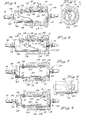
- a fuel saver 20 in accordance with the invention is illustrated.
- the fuel saver is shown in Fig. 1 in communication with an intake manifold 22 of an internal combustion engine used in a vehicle (not shown).
- the fuel saver is shown connected at 24 to a conduit 26 leading from a conventional carburetor -28 to the intake manifold 22.
- the connection at 24 is located downstream of a throttle valve 30 and idle fuel jets 32 so that the intake manifold vacuum may be regulated.
- the operation and structural features of the carburetor 28, throttle valve 30 and idle fuel jets 32 are well known and need not be described in further detail.
- the fuel saver 20 may be mounted directly to conduit 26 or as shown in Fig. 1 inserted in a vacuum hose 34 leading from the connection at 24 to a convenient mounting place.
- the fuel saver 20 may be inserted in a vacuum hose 34, which is pneumatically coupled to intake manifold 22 and may be used to drive other components of the vehicle.
- the fuel saver 20 operates to admit ambient air, as suggested by arrows 36, in a controlled manner from an air inlet 38 to the intake manifold 22.
- the fuel saver 20 is formed with a rectangular housing 40 having a control port 42 which is adapted to receive hose 34 as shown or may be directly connected to the intake manifold 22.
- Housing 40 which may be formed of an integrally plastic molded unit, is provided with three side by side located valves 44,46 and 48 which are interposed between air inlet 38 and control port 42.
- Valves 44 and 46 are located adjacent housing side walls, 47.1, 47.2 and are each formed with a valve seat 50 (such as 50.1 and 50.2) and a valve element 52 (such as 52.1 and 52.2) in the form of a ball and a spring 54 (such as 54.1 and 54.2) to normally seat balls 52.1 and 52.2 respectively on valve seats 50.1 and 50.2 and close off valve openings 55.1 and 55.2. Valves 44 and 46 are thus normally biased closed.
- valve 48 centrally located between housing side walls 47.1, 47.2, is formed with a valve seat 56 onto which a valve element 58 seats to close valve 48.
- Valve element 58 is in the form of a ball captured in a valve chamber 59. In the absence of a vacuum at control port 42 when ball 58 is forced against valve seat 56, ball 58 drops onto support 60 to open valve 48.
- valves 44, 46 and 48 are each provided with passageways 62, such as 62.1, 62.2 and 62.3 which are in communication with control port 42 via a control conduit 64 extending from control port 42 to intersect passageways 62.
- An air filtering material 66 is located in a recess 68 at air inlet 38 of housing 40 to maintain valves 44, 46 and 48 free of particles and dirt.
- FIG. 1 has an air inlet 38 from which valves 44, 46 and 48 admit ambient air to control port 42. It should be understood, however, that such air inlet may be separately provided for each of the valves.
- the term air inlet as used herein is intended to include such other or separate air inlets as may be provided for the several valves in a fuel saver in accordance with the invention.
- valves 44, 46 and 48 each are operative during a particular operational mode of the engine.
- Valve 44 is set to open when the vacuum at the control port 42 is above a predetermined upper vacuum limit set relative to the vacuum developed during an idling mode for the engine.
- the force supplied by spring 54.1 is selected by choosing the proper spring or varying the spring force by adjusting a screw spring force selector 70.1, to which spring 54.1 is anchored, towards or away from valve seat 50.1.
- the spring force selected for spring 54.1 is such that additional air is admitted to control port 42 if the intake manifold vacuum tends to rise above a predetermined limit.
- This upper limit has been found to influence the fuel economy which can be obtained with the fuel saver 20.
- This upper limit is preferably set relative to a vacuum developed by a particular repeatable engine mode. In the case of fuel saver 20, normally closed control valve 44 is set to open at a particular vacuum level below the vacuum developed during a fast idle mode of the engine. Thus, for one engine it was found that the preferred upper vacuum limit above which control valve 44 should open was about one inch of mercury below the vacuum level developed at a fast engine idle mode of about 2000 rpm.
- fuel economy may change. For example, when the upper limit was set for a lower vacuum level of say three inches below the vacuum level of the fast engine idle mode, fuel economy suffered instead of improved. Similarly, at high vacuum levels for the upper limit, fuel economy tended to change.
- valve 44 The vacuum level setting for the opening of valve 44 tends to depend upon different engines. Generally the valve 44 is set to open at an upper vacuum limit which falls in a range from about five to fifteen percent below the vacuum level developed during a fast engine idle mode. In some instances fuel economy was obtained at a setting of one inch of mercury below the vacuum level of 18 inches of mercury developed during a fast engine idle mode of 2000 rpm. Improvements in fuel economy, such as a higher miles per gallon fuel consumption, were obtained at upper vacuum limited extending from about one to about two and a half inches of mercury below the vacuum level at a fast engine idle of 2000 rpm.
- valve 46 is set to open when the intake manifold tends to be driven into a high vacuum such as may occur during engine deceleration when the air flow through open valve 44 is insufficient to maintain the intake manifold at the vacuum level where valve 44 opens. During such deceleration mode a relatively large volume of air is needed to maintain the intake manifold at a desired vacuum level. Accordingly, valve 46 in cooperation with the already opened valve 44, is selected to open at a higher intake manifold vacuum level than the vacuum level at which valve 44 opens. An intake manifold vacuum level which is several inches of mercury higher than the level at which valve 44 opens was found sufficient for the opening of valve 46.
- valve 46 advantageously increases the amount of air flowing to control port 42 during deceleration, while allowing both valves 44 and 46 to properly operate. As a result, a smoother air flow and improved vibrational behaviour is obtained with fuel saver 20 over a wide range of engine operating modes. Adjustment to select the opening vacuum level for valve 46 can be obtained in a similar manner as for valve 44.
- a screw spring force adjuster 70,2 to which spring 54.2 is anchored is mounted in housing 40 for movement toward or away from valve seat 50.2.
- valve 44 opens first followed by valve 46.
- the valves are so sized such that, when opened, they may vibrate.
- Such valve element vibration is deemed desirable when accompanied with small valve openings (small displacement of a ball 52 from its seat 50) to improve fuel mixing action at the intake manifold by the pulsating action of the air flow.
- Valve 48 is closed whenever the intake manifold has a vacuum above a preset acceleration level. This level is selected so that during engine modes such as start up, idle, cruising and deceleration, valve element 58 is seated on valve seat 56 to close valve 48.
- valve element 58 drops onto a central opening of 74 in support 60 to open valve 48 as shown in dotted line in Fig. 2. This enables air to pass through slots 72, extending radially from central opening 74 around valve element 58 to control port 42.
- the air admitted by the opened valve 48 enters the engine intake manifold 22 below the throttle valve 30. This additional air tends to improve fuel mixture while reducing the fuel drawn from the venturi fuel source normally employed inside the engine carburetor 28.
- Valve 28 requires an inclined orientation to operate. A vertical orientation is preferred, though this has not been found necessary.
- the preset acceleration vacuum level below which valve 48 opens is determined by selecting the weight of element 58 and the cross sectional area of the valve seat opening 62.3. On one fuel saver 20 the valve 48 was set to open when the vacuum at control port 42 would drop below a preset acceleration level of about 12.5 cm of mercury.
- the fuel saver was tested in a 3710 lb (1.75 tonne) curb weight 1979 Pontiac Cataline with a six cylinder engine of 3.8 liters.
- the fuel consumption with the fuel saver was found to yield a fuel economy as high as about 5.8%, i.e. from 14.48 miles per gallon (approx 5.19 km/litre) to 15.51 miles per gallon (approx 5.91 km/litre) over an intricate test drive course.
- this optimum vacuum level at which supplemental air from valve 44 was allowed to flow was at about one-half inch of mercury (about 1.25 cm or 3 percent) below the 18 inch (45cm) vacuum level occurring at a fast idle engine mode of 2000 rpm.
- A. 4.9% miles per gallon improvement was obtained at an upper limit of about one inch (2.5cm, about 5%) below the 18 inch fast idle vacuum level.
- valve 44 When the fuel saver 20 was installed in a Buick LsSabre 1974 model having a 455 CID V8 engine in a 4400 lb (2 tonne) curb weight model, about seven percent improvement in fuel economy was obtained at a setting for valve 44 of about 1.5 inches (3.75 cm) of mercury (about 10% below a fast idle vacuum level of 1.8 inches (4.5 cm). Fuel economy was still obtained as the upper limit for opening of valve 44 was descreased to two and then two and a half inches (about 15%) below the fast idle vacuum level of 18 inches. At higher vacuum levels (generally less than about 5% below the fast engine idle vacuum level) and at lower vacuum levels of below about 15%, no fuel economy was obtained and in fact appeared to result in an increase in fuel consumption. The selection of the vacuum level at which 44 would be set to open, thus was found to be critical in obtaining a fuel economy over a broad range of driving conditions. High fuel economies may in some cases be obtained.
- Installationof fuel saver 20 to an engine in an automobile may be conveniently carried out.
- the largest vacuum hose 34 in the engine compartment such as the vacuum line leading to the power brake system, is severed.
- the ends such as 43.1 and 43.2 in communication with control port 42 are inserted in the severed line.
- Clamps (not shown) may be used to firmly affix the vacuum hose to fuel saver ends 43.1 and 43.2.
- Setting of valve 44 is obtained by measuring, with a conventional vacuum gauge connected to the hose leading to the intake manifold, the vacuum developed at a fast enging idle speed (from about 1500 to about 2000 rpm). Such idle speed can be quickly determined employing equipment commonly available at a gas station. The fast idle vacuum level as measured by the gauge in inches or centimeters of mercury is recorded at a time when the engine is thoroughly warmed up.
- the end 43.1 of the fuel saver 20 is then inserted in the vacuum hose 34 leading to intake manifold 26 and the gauge connected or otherwise permanently coupled to fuel saver end 43.2.
- the engine speed is again set at the fast idle mode and the spring force selector 70.1 adjusted to register about a 5% (about 1" or 2.5 cm mercury) lower reading on the vacuum gauge than what was previously recorded without the fuel saver 20.
- valve 46 normally does not require changing since its setting may be factory selected so as to open at a sufficiently higher vacuum than could be expected for valve 44.
- the fuel saver device When a car engine is tuned, the fuel saver device should be first removed, the vacuum line 34 closed off and reinstalled after tuning.
- a housing 102 is provided with a through bore 104.
- the housing 102 is cylindrical with other shapes being usable.
- the axial ends of housing 102 are provided with closures 106, 108 which include conduit fittings 110 to which a vacuum hose such as 34 in Fig. 1 can be attached.
- valves such as 44 and 46 are provided, but formed in a different manner.
- a longitudinal spring 112 such as a leaf spring is attached in cantilever fashion with a suitable fastener 114 inside bore 104.
- the spring 112 is shown in Fig. 5 in a normally valve closure position whereby spring 112 fits generally parallel with the internal wall 116 of bore 104 in an axial direction.
- first and second valve seats 120, 122 Opposite spring 112 and at predetermined spacings from the fastened end 118 of spring 112, are first and second valve seats 120, 122 with openings leading to an air inlet.
- Thr spring 112 is provided with valve elements 124, 126 located to be normally seated on valve seats 120, 122 under spring bias action from spring 112.
- the housing 102 is provided with a sleeve 134 formed of a porous filter material to maintain valves 44, 46 free of dirt.
- the spring 112 and the size of valve 44 are selected such that the cantilevered end 128 of spring 112 is forced to flex away from wall 116 to open valve 44 commencing at the desired engine idle vacuum pressure.
- spring 112 flexes further away from wall 116 to open valve 46 in addition to valve 44 as illustrated in Fig. 7.
- Opening of valves 44, 46 in fuel saver 100 depends upon the surface area of valve openings 130, 132 in wall 116, the spacing S between valve elements 124, 126 and the spring force applied by spring 112.
- the area of openings 130, 132 need not be the same and are further selected in view of the amount of air to be passed during particular operating modes of the engine with which the fuel saver is intended to operate.
- valve 152 is similar to a valve as shown in Fig. 5 with a leaf spring 112, valve element 156, valve seat 158 and valve opening 160.
- the sizing of valve 152 is selected in such manner that it serves the function of both valves 44 and 46 in fuel saver 100 of Fig. 5. Alternatively, the latter valves may be used in fuel saver 150.
- Valve 154 is an acceleration air supply valve mounted inside bore 104 of housing 102 with a leaf spring 164 anchored at 166.
- Spring 164 is provided with a valve element 168 which seats over valve opening 170 to close the valve 154.
- the spring 164 normally biases valve element 168 to open valve 154 as shown in Fig. 7. In such case spring 164 partially covers valve opening 170 leaving side located air passages 172, 174 as shown in Fig. 8.
- the small force from spring 164 is selected such that it opens with a small pressure differential as occurs during engine acceleration and closes as soon as the intake manifold pressure drops below a pressure level which is higher than the vacuum pressure needed to start the engine.
- the functions provided by the embodiment of Figs. 7-9 may also be achieved by employing the fuel saver of Fig. 2, but with one valve such as 46 deleted or blocked off.
- the fuel saver enables smooth engine operation throughout its operating modes while achieving a significant fuel economy.
Landscapes
- Engineering & Computer Science (AREA)
- Chemical & Material Sciences (AREA)
- Combustion & Propulsion (AREA)
- Mechanical Engineering (AREA)
- General Engineering & Computer Science (AREA)
- Control Of The Air-Fuel Ratio Of Carburetors (AREA)
- Control Of Throttle Valves Provided In The Intake System Or In The Exhaust System (AREA)
Applications Claiming Priority (4)
| Application Number | Priority Date | Filing Date | Title |
|---|---|---|---|
| US6252179A | 1979-08-02 | 1979-08-02 | |
| US167860 | 1980-07-22 | ||
| US06/167,860 US4344406A (en) | 1979-08-02 | 1980-07-22 | Fuel saver |
| US62521 | 1998-04-17 |
Publications (1)
| Publication Number | Publication Date |
|---|---|
| EP0023837A1 true EP0023837A1 (en) | 1981-02-11 |
Family
ID=26742363
Family Applications (1)
| Application Number | Title | Priority Date | Filing Date |
|---|---|---|---|
| EP80302667A Withdrawn EP0023837A1 (en) | 1979-08-02 | 1980-08-04 | Fuel saver for internal combustion engines |
Country Status (5)
| Country | Link |
|---|---|
| US (1) | US4344406A (enExample) |
| EP (1) | EP0023837A1 (enExample) |
| GB (1) | GB2060055A (enExample) |
| GR (1) | GR69890B (enExample) |
| IL (1) | IL60718A0 (enExample) |
Cited By (4)
| Publication number | Priority date | Publication date | Assignee | Title |
|---|---|---|---|---|
| WO1996034194A3 (en) * | 1995-04-27 | 1997-02-20 | Richard Nigel Bushell | Automatic valve for the inlet manifold of an internal combustion engine |
| EP1039120A3 (en) * | 1995-04-27 | 2000-11-08 | Richard Nigel Bushell | Automatic air bleed valve |
| RU2482642C1 (ru) * | 2011-10-12 | 2013-05-20 | Федеральное государственное бюджетное образовательное учреждение высшего профессионального образования "Национальный исследовательский Томский политехнический университет" | Источник тормозного излучения |
| RU2482641C1 (ru) * | 2011-10-12 | 2013-05-20 | Федеральное государственное бюджетное образовательное учреждение высшего профессионального образования "Национальный исследовательский Томский политехнический университет" | Источник тормозного излучения |
Families Citing this family (7)
| Publication number | Priority date | Publication date | Assignee | Title |
|---|---|---|---|---|
| US4425937A (en) | 1981-06-02 | 1984-01-17 | Myron Stein | Fluid injection system |
| US4660525A (en) * | 1984-01-30 | 1987-04-28 | Mesman Alexander H | Carburetor mixture controller apparatus |
| GB8728427D0 (en) * | 1987-12-04 | 1988-01-13 | Economic Combustion Systems Lt | Improved i.c.engine |
| US5694907A (en) * | 1995-09-26 | 1997-12-09 | Tseng; Wen-Chih | Gasoline engine booster |
| DE19952512A1 (de) * | 1999-10-30 | 2001-05-10 | Bosch Gmbh Robert | Druckverstärker und Kraftstoffeinspritzsystem mit einem Druckverstärker |
| US7117859B1 (en) | 2004-08-11 | 2006-10-10 | Roy Martin | Air bleed vapor system |
| US20060260590A1 (en) * | 2005-05-17 | 2006-11-23 | Lin Chun C | Control apparatus utilizing engine negative pressure for improving combustion efficiency thereof |
Citations (17)
| Publication number | Priority date | Publication date | Assignee | Title |
|---|---|---|---|---|
| FR542472A (fr) * | 1921-10-18 | 1922-08-12 | économiseur d'essence pour moteurs à explosions | |
| US1473317A (en) * | 1922-05-22 | 1923-11-06 | Vernon C Randall | Auxiliary air device |
| DE696433C (de) * | 1937-10-12 | 1940-09-20 | Bosch Gmbh Robert | Sicherheitsvorrichtung zum Verhindern des Stehenbleibens von Vergasermaschinen beim raschen Schliessen der Drosselklappe |
| DE835816C (de) * | 1950-06-22 | 1952-04-03 | Edmund Renner | Vorrichtung zum Zufuehren von Frischluft in das Brennstoffluftgemisch der Ansaugleitung bei Verbrennungskraftmaschinen |
| DE841372C (de) * | 1949-09-12 | 1952-07-10 | Josef Von Deschwanden | Vorrichtung zur Zufuehrung von Zusatzluft fuer insbesondere mit Vergaser arbeitende Brennkraftmotoren |
| US2749895A (en) * | 1952-10-29 | 1956-06-12 | United Specialties Co | Vacuum breaker |
| GB762531A (en) * | 1954-05-22 | 1956-11-28 | William John Samuel Dangerfiel | Extra air intake device for internal combustion engines |
| US3564580A (en) * | 1969-12-29 | 1971-02-16 | Dorado Research Corp | Anti-pollution device |
| US3575386A (en) * | 1969-04-25 | 1971-04-20 | Ford Motor Co | Device for reducing internal combustion engine hydrocarbon emissions |
| US3590793A (en) * | 1968-03-30 | 1971-07-06 | Nissan Motor | Apparatus for reducing hydrocarbon content of engine exhaust gases during deceleration of automobile |
| US3659575A (en) * | 1968-08-03 | 1972-05-02 | Leif Lokka | Vacuum breaker for automobile engines |
| US3677237A (en) * | 1970-12-21 | 1972-07-18 | Poul E Hansen | Auxiliary air valve |
| US3809035A (en) * | 1971-08-25 | 1974-05-07 | Ballmatic Corp | Air admission valve for internal combustion engines equipped with pollution control valve |
| US3977372A (en) * | 1975-06-06 | 1976-08-31 | Fernandez John J | Carburetor vacuum shutoff control valve |
| GB1507058A (en) * | 1974-09-17 | 1978-04-12 | Nissan Motor | Internal combustion engine having an intake manifold pressure regulator |
| DE2719775A1 (de) * | 1976-12-29 | 1978-07-06 | Toyota Motor Co Ltd | Vorrichtung zur steuerung des luft- kraftstoff-verhaeltnisses fuer eine brennkraftmaschine mit einem vergaser |
| GB1519584A (en) * | 1975-07-11 | 1978-08-02 | Mcfarlane J | A fuel economiser device |
Family Cites Families (4)
| Publication number | Priority date | Publication date | Assignee | Title |
|---|---|---|---|---|
| US1083789A (en) * | 1911-08-21 | 1914-01-06 | Gen Electric | Air-inlet valve for carbureters. |
| US1240303A (en) * | 1916-02-26 | 1917-09-18 | William H Brasier | Inspirator-valve for intake-manifolds. |
| US3585976A (en) * | 1969-10-13 | 1971-06-22 | Paul M Rider | Manifold vacuum controlled supplemental air inlet with air filtering means |
| US3799132A (en) * | 1973-04-09 | 1974-03-26 | Ferry Cap Set Screw Co | Valve device and system employing the same |
-
1980
- 1980-07-22 US US06/167,860 patent/US4344406A/en not_active Expired - Lifetime
- 1980-07-31 IL IL60718A patent/IL60718A0/xx unknown
- 1980-08-01 GR GR62583A patent/GR69890B/el unknown
- 1980-08-04 GB GB8025390A patent/GB2060055A/en not_active Withdrawn
- 1980-08-04 EP EP80302667A patent/EP0023837A1/en not_active Withdrawn
Patent Citations (17)
| Publication number | Priority date | Publication date | Assignee | Title |
|---|---|---|---|---|
| FR542472A (fr) * | 1921-10-18 | 1922-08-12 | économiseur d'essence pour moteurs à explosions | |
| US1473317A (en) * | 1922-05-22 | 1923-11-06 | Vernon C Randall | Auxiliary air device |
| DE696433C (de) * | 1937-10-12 | 1940-09-20 | Bosch Gmbh Robert | Sicherheitsvorrichtung zum Verhindern des Stehenbleibens von Vergasermaschinen beim raschen Schliessen der Drosselklappe |
| DE841372C (de) * | 1949-09-12 | 1952-07-10 | Josef Von Deschwanden | Vorrichtung zur Zufuehrung von Zusatzluft fuer insbesondere mit Vergaser arbeitende Brennkraftmotoren |
| DE835816C (de) * | 1950-06-22 | 1952-04-03 | Edmund Renner | Vorrichtung zum Zufuehren von Frischluft in das Brennstoffluftgemisch der Ansaugleitung bei Verbrennungskraftmaschinen |
| US2749895A (en) * | 1952-10-29 | 1956-06-12 | United Specialties Co | Vacuum breaker |
| GB762531A (en) * | 1954-05-22 | 1956-11-28 | William John Samuel Dangerfiel | Extra air intake device for internal combustion engines |
| US3590793A (en) * | 1968-03-30 | 1971-07-06 | Nissan Motor | Apparatus for reducing hydrocarbon content of engine exhaust gases during deceleration of automobile |
| US3659575A (en) * | 1968-08-03 | 1972-05-02 | Leif Lokka | Vacuum breaker for automobile engines |
| US3575386A (en) * | 1969-04-25 | 1971-04-20 | Ford Motor Co | Device for reducing internal combustion engine hydrocarbon emissions |
| US3564580A (en) * | 1969-12-29 | 1971-02-16 | Dorado Research Corp | Anti-pollution device |
| US3677237A (en) * | 1970-12-21 | 1972-07-18 | Poul E Hansen | Auxiliary air valve |
| US3809035A (en) * | 1971-08-25 | 1974-05-07 | Ballmatic Corp | Air admission valve for internal combustion engines equipped with pollution control valve |
| GB1507058A (en) * | 1974-09-17 | 1978-04-12 | Nissan Motor | Internal combustion engine having an intake manifold pressure regulator |
| US3977372A (en) * | 1975-06-06 | 1976-08-31 | Fernandez John J | Carburetor vacuum shutoff control valve |
| GB1519584A (en) * | 1975-07-11 | 1978-08-02 | Mcfarlane J | A fuel economiser device |
| DE2719775A1 (de) * | 1976-12-29 | 1978-07-06 | Toyota Motor Co Ltd | Vorrichtung zur steuerung des luft- kraftstoff-verhaeltnisses fuer eine brennkraftmaschine mit einem vergaser |
Cited By (6)
| Publication number | Priority date | Publication date | Assignee | Title |
|---|---|---|---|---|
| WO1996034194A3 (en) * | 1995-04-27 | 1997-02-20 | Richard Nigel Bushell | Automatic valve for the inlet manifold of an internal combustion engine |
| US6102017A (en) * | 1995-04-27 | 2000-08-15 | Bushell; Richard Nigel | Automatic valve for the inlet manifold of an internal combustion engine |
| EP1039120A3 (en) * | 1995-04-27 | 2000-11-08 | Richard Nigel Bushell | Automatic air bleed valve |
| EP1039119A3 (en) * | 1995-04-27 | 2000-11-08 | Richard Nigel Bushell | Automatic air bleed valve |
| RU2482642C1 (ru) * | 2011-10-12 | 2013-05-20 | Федеральное государственное бюджетное образовательное учреждение высшего профессионального образования "Национальный исследовательский Томский политехнический университет" | Источник тормозного излучения |
| RU2482641C1 (ru) * | 2011-10-12 | 2013-05-20 | Федеральное государственное бюджетное образовательное учреждение высшего профессионального образования "Национальный исследовательский Томский политехнический университет" | Источник тормозного излучения |
Also Published As
| Publication number | Publication date |
|---|---|
| IL60718A0 (en) | 1980-09-16 |
| GB2060055A (en) | 1981-04-29 |
| GR69890B (enExample) | 1982-07-20 |
| US4344406A (en) | 1982-08-17 |
Similar Documents
| Publication | Publication Date | Title |
|---|---|---|
| US3523418A (en) | Exhaust back pressure control system for an internal combustion engine | |
| EP0023837A1 (en) | Fuel saver for internal combustion engines | |
| US5586541A (en) | Auxiliary assembly for improving the combustion efficiency of an engine | |
| US3503594A (en) | Fuel system | |
| US4186707A (en) | Fuel economizer system for internal combustion engines | |
| US4369749A (en) | Variable venturi carburetor | |
| US5386145A (en) | Fuel delivery means for carburetors for internal combustion engines and method for installing same | |
| CA1045484A (en) | Air bleed control for carburetor idle system | |
| US4090484A (en) | Fuel supply system for multi-fuel internal combustion engines | |
| US4658798A (en) | Turbocharger control system | |
| EP1026391A3 (en) | Carburettor with scavenging air and mixture passages for an engine | |
| US3034492A (en) | Vacuum controlled gas saver | |
| JPS5854256B2 (ja) | 内燃機関の空燃比制御装置 | |
| US3919365A (en) | Carburetor | |
| US4473510A (en) | Carburetor having air fuel ratio adjusting means | |
| US4454080A (en) | Fuel flow automatic modulating and economizing carburetor jet assembly | |
| US4593671A (en) | Supplemental carburetion device | |
| EP0012540A1 (en) | Apparatus for controlling the fuel to air ratio of the fuel mixture to an internal combustion engine | |
| US4226218A (en) | Carburetor idle jet control | |
| JPS5852348Y2 (ja) | 車両減速時の空燃比制御装置 | |
| JP2791432B2 (ja) | エンジンの燃料供給装置 | |
| US2358255A (en) | Fuel control apparatus | |
| CA1066973A (en) | Vacuum control valve for internal combustion engine | |
| JPH0324850Y2 (enExample) | ||
| EP0420647A1 (en) | Improvements in combustion engines |
Legal Events
| Date | Code | Title | Description |
|---|---|---|---|
| PUAI | Public reference made under article 153(3) epc to a published international application that has entered the european phase |
Free format text: ORIGINAL CODE: 0009012 |
|
| AK | Designated contracting states |
Designated state(s): DE IT |
|
| STAA | Information on the status of an ep patent application or granted ep patent |
Free format text: STATUS: THE APPLICATION IS DEEMED TO BE WITHDRAWN |
|
| 18D | Application deemed to be withdrawn |
Effective date: 19820120 |
|
| RIN1 | Information on inventor provided before grant (corrected) |
Inventor name: CLOUTIER, EDWARD J.F. Inventor name: MINOR, ROBERT N. |