EP0023624A2 - Mass-compensated tamping or striking system - Google Patents
Mass-compensated tamping or striking system Download PDFInfo
- Publication number
- EP0023624A2 EP0023624A2 EP80104120A EP80104120A EP0023624A2 EP 0023624 A2 EP0023624 A2 EP 0023624A2 EP 80104120 A EP80104120 A EP 80104120A EP 80104120 A EP80104120 A EP 80104120A EP 0023624 A2 EP0023624 A2 EP 0023624A2
- Authority
- EP
- European Patent Office
- Prior art keywords
- tool
- mass
- piston
- tools
- tool carrier
- Prior art date
- Legal status (The legal status is an assumption and is not a legal conclusion. Google has not performed a legal analysis and makes no representation as to the accuracy of the status listed.)
- Granted
Links
- 239000000725 suspension Substances 0.000 claims abstract description 21
- 230000005284 excitation Effects 0.000 claims abstract description 16
- 238000005056 compaction Methods 0.000 claims abstract description 10
- 230000033001 locomotion Effects 0.000 claims description 22
- 238000005096 rolling process Methods 0.000 claims description 12
- 239000012530 fluid Substances 0.000 claims description 7
- 230000010363 phase shift Effects 0.000 claims description 6
- 238000002679 ablation Methods 0.000 claims description 4
- 238000003754 machining Methods 0.000 claims description 3
- 238000005065 mining Methods 0.000 abstract description 5
- 239000002689 soil Substances 0.000 abstract description 5
- 238000010276 construction Methods 0.000 abstract description 3
- 238000006243 chemical reaction Methods 0.000 description 6
- 239000000463 material Substances 0.000 description 4
- 230000010355 oscillation Effects 0.000 description 4
- 230000009977 dual effect Effects 0.000 description 3
- 239000011435 rock Substances 0.000 description 3
- 230000008901 benefit Effects 0.000 description 2
- 230000000694 effects Effects 0.000 description 2
- 238000000034 method Methods 0.000 description 2
- 230000008569 process Effects 0.000 description 2
- 241001295925 Gegenes Species 0.000 description 1
- 230000009471 action Effects 0.000 description 1
- 238000009412 basement excavation Methods 0.000 description 1
- 238000010009 beating Methods 0.000 description 1
- 230000015572 biosynthetic process Effects 0.000 description 1
- 239000000356 contaminant Substances 0.000 description 1
- 230000008878 coupling Effects 0.000 description 1
- 238000010168 coupling process Methods 0.000 description 1
- 238000005859 coupling reaction Methods 0.000 description 1
- 230000002950 deficient Effects 0.000 description 1
- 238000006073 displacement reaction Methods 0.000 description 1
- 230000002349 favourable effect Effects 0.000 description 1
- 230000005484 gravity Effects 0.000 description 1
- 230000002452 interceptive effect Effects 0.000 description 1
- 230000007774 longterm Effects 0.000 description 1
- 230000007246 mechanism Effects 0.000 description 1
- 230000003534 oscillatory effect Effects 0.000 description 1
- 238000007789 sealing Methods 0.000 description 1
- 239000000758 substrate Substances 0.000 description 1
- 230000001360 synchronised effect Effects 0.000 description 1
- 230000005641 tunneling Effects 0.000 description 1
Images


Classifications
-
- E—FIXED CONSTRUCTIONS
- E02—HYDRAULIC ENGINEERING; FOUNDATIONS; SOIL SHIFTING
- E02D—FOUNDATIONS; EXCAVATIONS; EMBANKMENTS; UNDERGROUND OR UNDERWATER STRUCTURES
- E02D3/00—Improving or preserving soil or rock, e.g. preserving permafrost soil
- E02D3/02—Improving by compacting
- E02D3/046—Improving by compacting by tamping or vibrating, e.g. with auxiliary watering of the soil
Definitions
- the invention relates to a mass-compensated ramming and / or beating system with at least one pair of tools from two ramming or striking tools, which are connected to a common tool carrier and oscillate in push-pull.
- the resonance behavior of the system can cause uncontrollable oscillatory movements and forces, which must be avoided in these areas.
- the object of the invention is to provide a mass-compensated ramming and / or impact system with which an optimal compensation of the forces and moments transmitted to the tool carrier or machine frame is achieved, in particular even when a large number of tools are provided on a common tool carrier is.
- a mass-compensated ramming and / or striking system of the type mentioned at the outset which is characterized according to the invention in that each ramming or striking tool is assigned to a two-mass vibration exciter system, the oscillating masses of which are essentially positively guided in a linear manner without suspension and that the phase relationship of the vibrating masses is chosen so that the resultant of all mass forces at least is approaching zero.
- Each two-mass vibration excitation system is balanced so that the product of the individual mass and the associated amplitude of its linear oscillation movement is equal to the corresponding product of the opposite side, the tools of a pair of tools oscillating in push-pull.
- Each individual two-mass vibration excitation system is therefore mass-compensated in itself.
- the products from the respective mass and the associated vibration path amplitude are always the same size in relation to a fixed overall system focus. If one wanted to make full use of the effect of self-compensation of the mass forces of a two-mass system, then one would have to make the suspension in the main focus of the system.
- the tool can be a soil compaction tool or an excavation tool, while the dual mass vibration exciter system can be rigidly attached to the common tool carrier or can be suspended in a spring-loaded manner.
- each vibration excitation system contains a double-acting piston / cylinder device with a piston, the two end faces of which can preferably be acted upon by a hydraulic fluid.
- This piston drives one vibrating mass and the associated cylinder drives the other vibrating mass ner linear movement.
- An arrangement with two eccentric masses can also be provided as the drive of the vibration exciter system, each rotating in opposite directions about an axis and arranged parallel next to one another, as a result of which they set the housing surrounding them with attached tools into linear vibrations.
- Each individual two-mass vibration exciter system can be suspended on the common tool carrier or machine frame in a rigid, springy manner or also via a hydraulic or pneumatic lifting and compensating device with a piston / cylinder arrangement.
- the latter embodiment is particularly favorable because it enables the height of each individual tool to be adjusted and the forces transmitted from a two-mass system to the tool carrier to be compensated for by a second two-mass system, which is paired with the former system and oscillates in opposite phase to it.
- the piston / cylinder arrangements are double-acting and the corresponding cylinder chambers are connected to one another. The piston movements effective in the direction of the tool carrier then cause a displacement of the hydraulic fluid in each case to the corresponding cylinder chamber of the other system, so that these forces are kept away from the tool carrier.
- the pairing of three dual mass systems is provided.
- the phase shift of the vibration amplitudes to each other is 120 °, because with this arrangement the addition of the instantaneous values for sinusoidal vibration movement becomes zero.
- an anti-rotation device which according to one embodiment is one at the factory Tool carrier attached guide rod and a tool attached, slidably mounted on the guide rod bushing.
- the tool carrier is designed as a processing head of a compaction or ablation machine on which the tool pairs e.g. Axially symmetrical or rotationally symmetrical are arranged, wherein the tools themselves can swing in a direction inclined to the vertical, on the plane of the tool carrier.
- a number of tools can be arranged in a circle on the circumference of the machining head, while the machining head itself can be designed to be rotatable.
- At least two tool pairs are arranged on a common mobile machine frame in a straight row, the tool pairs being arranged one behind the other in the direction of travel, for example three tool pairs can be provided.
- the tool is in the form of a roller, with a roller drum being rotatably mounted on the one vibrating mass of the vibration exciter system.
- the roller drum can be provided with tool rings for material removal.
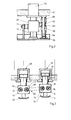
- the embodiment of the mass-compensated ramming system shown in FIG. 1 contains a tool holder designed as a machine frame 10, on which a plurality of ramming tools are suspended, of which a pair of tools 12, 14 is shown in FIG. 1.
- Each tool 12, 14 is assigned a dual mass vibration exciter system, generally designated 16 and 18, respectively.
- This essentially consists of a double-acting hydraulic piston / cylinder device with a cylinder 20, 22 and a piston 24, 26. Both end faces 24A, 24B and 26A, 26B of the piston 24 and 26 can be acted upon by a hydraulic fluid.
- the two pistons 24, 26 are at 180 ° Phase shift driven linearly.
- the ramming tools 12, 14 are thereby driven with a linear oscillating movement, which is used to solidify or compact the underlying soil.
- Each tool and the associated vibration exciter are suspended by means of a hydraulic piston / cylinder arrangement 28 or 30.
- Each piston / cylinder arrangement 28, 30 contains a cylinder 32 or 34 which is fixedly connected to the machine frame 10 and a piston 36 or 38 which slides therein.
- the two piston / cylinder arrangements 28, 30 are also double-acting; the piston 36 and 38 thus has two end faces 36A, 36B and 38 A , 38b on which the hydraulic fluid can act.
- the two cylinder chambers 32B, 34B facing the tool are connected to one another via a line 40 or 42 and an electromagnetically operated shut-off valve 44 or 46; they are also connected via a directional valve 48 with three positions and via an adjustable pressure relief valve 50 to a pressure source 53 which is designed as a pump which is driven by a motor.
- the two other cylinder chambers 32A, 34A are connected to one another via lines 52 and 54 and shut-off valves 56 and 58 and can also be connected directly to the pressure source 53 via the directional valve 48.
- FIG. 1 shows the middle position of the directional control valve 48, in which the cylinder chambers are shut off from the pressure source 53, but an internal compensation of the cylinder chambers 32A, 34A or 32B, 34B via the opened valves 44, 46 or 56, 58 is possible.
- the hydraulic system for controlling the piston / cylinder arrangements 28, 30 can be controlled differently.
- a defined pressure is supplied to the cylinder chambers 32A, 34A, while the cylinder chambers 32B, 34B are relieved. This creates a defined load under which the tool masses vibrate. The tools act on the ground due to the constant load.
- the pistons 36, 38 are first brought to the desired level by suitable control of the various valves, and then the directional control valve 48 is closed, that is to say into the middle position in FIG. 1 brought.
- valves 44, 46, 56, 58 serve primarily to position a single piston / cylinder arrangement 28 or 30, because by closing the valves 44 and 56 e.g. the unit 28 can be excluded from the positioning process (by switching the directional valve 48).
- An overpressure safety device can be provided in the hydraulic system to make suddenly occurring forces harmless, e.g. in the event of sudden, uneven floors.
- the directional control valve 48 can also be designed as a control valve with appropriate control, e.g. to keep a certain vibration center of the tools constant, or to grant a certain tracking rate.
- the vibration exciter systems are preferably equipped with an anti-rotation device if the tool is not rotationally symmetrical.
- an anti-rotation device is shown in FIG. 2.
- Fig. 2 shows only the essential parts of a single tool, the associated vibration exciter and the machine frame.
- a connector 60 acts laterally, which is rigidly connected to a guide bush 62.
- the guide bush 62 is slidably mounted on a shaft 64 which is rigidly connected to the machine frame 10 at its upper end and is guided at its lower end in a bush 66 rigidly attached to the tool 12.
- Bellows 66, 68 which enclose the free part of the shaft 64, serve to seal against the ingress of dirt and the like.
- an embodiment with a push-elastic rubber element 17 is shown on the left in FIG. 2.
- the spring stiffness in the direction of vibration is chosen to be low so that the restoring forces are negligible.
- FIG. 3 shows, similar to FIG. 1, two ramming tools 12, 14 with the associated vibration exciters 16, 18 and piston / cylinder arrangements 28, 30 for suspending the tools on the machine frame 10.
- the vibration exciters are different from the embodiment according to FIG 1 not designed as a linear drive, but as an eccentric drive.
- Each vibration exciter contains two mutually parallel shafts 70, 72 or 74, 76, on each of which an eccentric mass 78, 80 or 82, 84 is mounted.
- the rotary movements of the eccentric masses are synchronized with each other and he follow in opposite directions within a vibration system with different directions of rotation.
- neighboring systems also vibrate with a 180 ° phase shift.
- the synchronization between two adjacent vibration exciters can take place, for example, by means of a toothed belt 86 or the like, which connects two adjacent shafts 72, 74 of two adjacent vibration exciters 16, 18 to one another. This ensures that the tools 14, 12 swing in push-pull.
- the piston / cylinder arrangements 28, 30 are controlled in the same way as in FIG. 1.
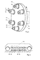
- ablation tools 88 with the associated vibration exciters 90 are arranged on a common, circular disk-shaped tool carrier 92, which is also referred to as a shield.
- This tool carrier is attached to the end of a rotatable cantilever arm 94.
- the formation of the vibration exciter 90 corresponds to that of FIGS. 1 and 2 and therefore need not be explained further.
- the tools 88 are chisel-shaped and are used for material removal for tunnel or shaft driving in mining.
- the tools and associated vibration exciters are arranged on the circumference of the tool carrier 92 in such a way that their axes are inclined to the axis of the rotatable cantilever arm 94.
- This inclination causes a division of the impact force F in a Axialkompo- ne nth FA and a Radialkömponente F R 'Components F R support the rotational movement of the tool carrier and thus cause uniform ablation of the rock.
- a series of ramming tools 96 with the associated vibration exciters 98 are suspended in a straight line one behind the other on a common mobile machine frame 100.
- six ramming tools are provided, which are designed as in the embodiment shown in FIG. 1.
- the schematic representation shows the tools one behind the other in the direction of travel; Of course, several tools can also be arranged side by side. Two neighboring tools and vibration exciters can form a pair. the. However, it is also possible to couple non-adjacent tools in pairs.
- An inclination of the tool axes to the vertical can also be provided here, e.g. to support locomotion.
- FIG. 6 shows an embodiment with a rolling, vibrating tool in the form of a drum casing 102.
- a drum casing 102 with a smooth surface serves, for example, to solidify bulk goods.
- tool rings 106, 108 are also shown in dashed lines, which can be provided instead of a smooth drum surface and are used, for example, to remove rock or the like.
- the drum jacket 102 is mounted at two diametrically opposite points on roller bearings 104 on a yoke 110, which is rigidly connected to an end face of a piston 112.
- the piston 112 is slidably fitted in a cylinder 114 which is formed in the interior of an axis 116 in the radial direction.
- the axis 116 is rotatably mounted in a frame 120 attached to the machine frame 118.
- a crank 122 is firmly closed on one end of the axle 116, to which a piston rod 124 is articulated.
- This piston rod 124 is connected to the piston 126 of a double-acting adjusting cylinder 128 which is articulated on a holder 130 which is rigidly connected to the machine room 118.
- axis 116 can be pivoted through an angle 2S.
- the direction of oscillation of the piston 112 is also pivoted, so that it forms an angle ⁇ with respect to the vertical. In this way, a propulsion component is obtained from the impact force.
- the one mass of the vibration system namely the axis 116 and the cylinder 114, is rigidly mounted on the machine frame 118.
- the full reaction forces of the oscillating movement of the piston 112 and the parts driven thereby are therefore transmitted to the machine frame 118.
- At least two such tools are therefore provided on the same machine frame 118, which oscillate with a 180 ° phase shift.
- the machine frame 118 then processes the reaction forces as internal forces so that no external forces arise.
- the remaining moments which have the tendency to pivot the machine frame 118, are eliminated by arranging a further pair of tools on the same machine frame 118, the arrangement of the tool pairs taking place in mirror image.
- the tools of a pair are preferably arranged close to one another or one behind the other on the machine frame 118.
- Two axes 116 of a pair of tools can then be pivoted simultaneously by an adjusting cylinder 128.
- the two cranks 122 can be coupled by a push rod or the two axles can be coupled long and pivoted with a common crank.
- several pairs of tools are arranged on the tunneling shield of a tunnel boring machine or the like, similar to the embodiment according to FIG. 4.
- an anti-rotation device is provided, which is realized by a rod 132 connecting the two yokes 110, which is slidably mounted in a cylindrical bore 134 of the axis 116.
- sealing elements 136 are provided which close the end of the rolling tool.
- Hydraulic lines 138, 140 are fed through the axis 116 in the form of axial bores to feed the cylinder 114.
- Rolling tools are also provided in the embodiments shown in FIGS. 8 and 9.
- a roller-shaped tool 142 which can be provided with tool rings 144, is rotatably mounted on an axis 148 via slide or roller bearings 146.
- the axis 148 is rigidly mounted in a fork-shaped holder 150.
- the holder 150 is rigidly connected to the piston 152 of a double-acting hydraulic cylinder 154, which represents the linear drive of the tool.
- the cylinder 154 is rigidly connected to the tool carrier 156.
- a yoke 158 is rigidly connected to the piston 152 and has at its opposite ends guide bolts 160 directed towards the tool carrier 156, which are slidably guided in bushings 162 which are fastened to the tool carrier 156.
- This anti-rotation lock can be omitted if a rotationally symmetrical tool is used.
- the arrangement of elastic rubber elements between the frame 156 and the yoke 158 similar to the embodiment according to FIG. 2 is conceivable as a further protection against rotation.
- the embodiment according to FIG. 9 differs from that according to FIG. 8 in that two rolling tools 164 are provided which are rotatably mounted on the outer ends of an axle shaft 166 which is supported in its central region by a rod-shaped holder 168.
- reaction forces are transmitted to the machine frame 156. Therefore, at least two tools are always paired and arranged on the tool carrier 156 with a 180 ° phase shift. To eliminate the remaining moments, two pairs of tools with a mirror-image arrangement are preferably provided.
- a rigid suspension of the vibration exciter system on the machine frame has the advantage that the entire piston stroke is available for the tool movement.
- an elastic suspension of the vibration exciter and the tool driven by it on the machine frame is advantageous.
- Corresponding embodiments are shown in FIGS. 10 and 11.
- the embodiment according to FIG. 10 is the same as that according to FIG. 6, so that only the different features compared to FIG. 6 are explained.
- the yoke 110 is connected on both end faces to an annular suspension plate 168, on the end face of which a likewise annular fastening plate 170 is fastened.
- a corresponding mounting plate 172 is connected in parallel to the machine frame 174.
- a vulcanized, ring-shaped, elastic suspension element 176 by means of which the tool with the associated vibration exciter is suspended on the machine frame. Due to the ring-shaped suspension element 176, the interior of the tool is simultaneously turned outwards sealed and thus protected against the ingress of contaminants.
- rolling compaction tools on compaction machines for earthworks and road construction are provided with rotating unbalances for generating vibrations. These unbalances cause a so-called non-directional swinging movement of the cylindrical tool, ie the swing path amplitude is all around a center.
- the vibration movement is not only perpendicular to the surface to be compacted, but also parallel to it, ie in the direction of travel of the machine. Since the compaction tools of such machines usually also have to perform drive and steering functions, the horizontal components of the swinging movement have an unfavorable effect on the suspension in the machine frame. On the one hand, the elastic elements for suspension should have as little spring stiffness as possible so that the machine frame is largely spared dynamic vibrating forces. On the other hand, the drive and steering function of the rolling tool requires a relatively hard suspension in the horizontal direction so that instabilities in traction and cornering behavior are prevented, which in turn results in a higher vibration load on the machine frame and thus on the entire device, including the operator.
- the solution to the problem according to the invention i.e. To a large extent keep the machine frame free from dynamic forces from the tool movement - is achieved in the embodiments according to FIGS. 10 and 11 in that the two-mass linear excitation system used generates vibrations in one direction only.
- the spring stiffness of the suspension elements 176 can be designed differently in the main axes. For example, a relatively low spring stiffness is provided in the direction of the vibration, but a relatively large spring stiffness in the direction perpendicular to the vibration, and the disadvantages described are thus avoided.
- the embodiment according to FIG. 11 essentially differs from that according to FIG. 10 in that the vibration exciter of the tool is rotatably mounted on the machine frame.
- the two outer fastening plates 172 are connected to a flange 178 of a bearing hub 180, which is mounted on roller bearings 182 in a cylindrical bore in the machine frame 174.
- the anti-rotation device 132, 134 of the embodiments according to FIGS. 6 and 10 is not shown for the sake of simplicity, but is preferably also present.
- the direction of oscillation of the tool can be adjusted by pivoting the axis 116, whereby a pivoting mechanism similar to that in the embodiment according to FIGS. 6 and 7 can be provided, which is attached to one of the bearing hubs 180 attacks.
- two lateral guide columns 184, 186 are provided instead of an elastic suspension on the machine frame.
- a piston 112 is mounted with a tool foot 188, which forms the lower mass.
- the cylinder spaces 114A, 114B are acted on alternately, and both masses oscillate against one another in accordance with the law of maintaining the center of gravity of the system, the relatively heavier upper mass carrying out the lower oscillation amplitude.
- a directional control valve 190 which is fed by a pressure source 192, the chambers 184A, 184B and 186A, 186B of the two guide cylinders 184, 186 are connected to one another, so that the upper mass oscillates freely with respect to the machine frame 194 without generating support forces can.
- the guide cylinders 184, 186 are with their jackets on the machine frame 194 and with theirs Piston rods attached to the upper mass.
- An anti-rotation device according to FIG. 2 can be arranged between the upper mass and the tool foot 188.
- the entire unit can be raised or lowered, or if valve 190 is used as a control valve, a specific load or tracking rate can be specified (see page 101).
- FIG. 13 shows an embodiment in which a ramming system comprising a cylinder 196 and piston 198 with a ramming tool 200 attached to it is articulated on a machine frame 206 via two trailing arms 202, 204.
- the articulation point 208 of the trailing arm 202 on the machine frame 206 is fixed, while the trailing arm 204 is articulated on the machine frame via a horizontally displaceable bearing 210, which can be moved or blocked by means of an adjusting cylinder 212. This allows the tool axis to be inclined towards the floor as required.
- the adjusting cylinder 212 can be driven periodically, the frequency being adjustable in such a way that a horizontal component is superimposed on the tool movement, which compensates for the relative movement of a movable tool carrier to the ground in the contact area between the tool and the ground . This ensures that, when the tool hits the ground, the tool has only a vertical component in its movement relative to the ground and thus the surface of the processed ground is not stressed in the horizontal direction. This ensures that even with very shear sensitive surfaces, no cracks can occur due to horizontal movement components of the tools during compaction.
Landscapes
- Engineering & Computer Science (AREA)
- Structural Engineering (AREA)
- Life Sciences & Earth Sciences (AREA)
- General Engineering & Computer Science (AREA)
- Environmental & Geological Engineering (AREA)
- General Life Sciences & Earth Sciences (AREA)
- Mining & Mineral Resources (AREA)
- Paleontology (AREA)
- Civil Engineering (AREA)
- Agronomy & Crop Science (AREA)
- Soil Sciences (AREA)
- Road Paving Machines (AREA)
- Investigation Of Foundation Soil And Reinforcement Of Foundation Soil By Compacting Or Drainage (AREA)
- Disintegrating Or Milling (AREA)
- Curing Cements, Concrete, And Artificial Stone (AREA)
- Diaphragms For Electromechanical Transducers (AREA)
- Percussive Tools And Related Accessories (AREA)
- Apparatuses For Generation Of Mechanical Vibrations (AREA)
- Presses And Accessory Devices Thereof (AREA)
- Perforating, Stamping-Out Or Severing By Means Other Than Cutting (AREA)
Abstract
Ein massenkompensiertes Stampf- und/oder Schlagsystem, wie eine Bodenverdichtungsmaschine für den Strassenbau oder Abbaumaschine für den Bergbau, umfasst mindestens ein Werkzeugpaar aus zwei Stampf- bzw. Schlagwerkzeugen, die mit einem gemeinsamen Werkzeugträger verbunden sind und im Gegentakt schwingen. Die bei solchen Systemen vorhandene Schwierigkeit der Übertragung von Kräften und Momenten auf den Werkzeugträger bzw. den Maschinenrahmen wird dadurch vermieden, dass jedes Stampf- bzw. Schlagwerkzeug einem Zweimassen-Schwingungserregersystem zugeordnet ist, dessen schwingende Massen im wesentlichen federungsfrei linear zwangsgeführt sind, und dass die Phasenbeziehung der schwingenden Massen so gewählt ist, dass die Resultierende aller Massenkräfte wenigstens angenähert zu Null wird.A mass-compensated ramming and / or striking system, such as a soil compaction machine for road construction or mining machine for mining, comprises at least one pair of tools from two ramming or striking tools, which are connected to a common tool carrier and oscillate in push-pull. The difficulty of transmitting forces and moments to the tool carrier or the machine frame, which is present in such systems, is avoided in that each ramming or striking tool is assigned to a two-mass vibration excitation system, the oscillating masses of which are essentially positively guided in a linear manner without suspension, and that The phase relationship of the vibrating masses is selected so that the resultant of all mass forces is at least approximately zero.
Description
Die Erfindung betrifft ein massenkompensiertes Stampf-und/oder Schlagsystem mit mindestens einem Werkzeugpaar aus zwei Stampf- bzw. Schlagwerkzeugen, die mit einem gemeinsamen Werkzeugträger verbunden sind und im Gegentakt schwingen.The invention relates to a mass-compensated ramming and / or beating system with at least one pair of tools from two ramming or striking tools, which are connected to a common tool carrier and oscillate in push-pull.
Bei mit vibrierenden Werkzeugen ausgestatteten Maschinen, z.B. Bodenverdichtungsmaschinen für den Straßenbau, Abbaumaschinen für den Bergbau usw., tritt allgemein die Schwierigkeit auf, daß die schwingenden Massensysteme Vibrationen auf den Maschinenrahmen übertragen. Durch diese Vibrationen wird der Maschinenrahmen Belastungen ausgesetzt, die auf Dauer zu Material ermüdung und Schäden führen können. Es wurden daher bereits verschiedene Anstrengungen unternommen, um massenkompensierte Stampf- und/oder Schlagmaschinen zu schaffen. Bei den meisten bisherigen Vibrationsmaschinen sind die schwingenden Massen federnd aneinander gekoppelt, und das aus zwei schwingenden Massen bestehende System ist als solches wiederum federnd an einem Maschinenrahmen angekoppelt. Derartige Lösungen sind grundsätzlich mit dem Mangel behaftet, daß die Kopplung der Feder-Massen-Systeme eine Anzahl störender Eigenfrequenzen beinhaltet. Im Falle, daß die Schwingungsfrequenz der Werkzeuge mit einer solchen Eigenfrequenz zusammentrifft bzw. in deren Nähe gerät, so können infolge des Resonanzverhaltens des Systems unkontrollierbare Schwingbewegungen und Kräfte hervorgerufen werden, wodurch ein Betrieb in diesen Bereichen vermieden werden muß. In der täglichen Praxis ist es jedoch erforderlich, die Schwingungsfrequenz der Werkzeuge an die jeweiligen vorherrschenden Verhältnisse anzupassen. z.B. an die Bodenbeschaffenheit, wenn Verdichungswerkzeuge zum Einsatz gelangen, oder an die Materialbeschaffenheit, wenn mit der Maschine Abtragungsarbeiten durchgeführt werden sollen.In machines equipped with vibrating tools, for example soil compaction machines for road construction, mining machines for mining, etc., the difficulty generally arises that the vibrating mass systems transmit vibrations to the machine frame. These vibrations expose the machine frame to loads that can lead to material fatigue and damage in the long term. Various efforts have therefore already been made to create mass-compensated ramming and / or striking machines. In most previous vibration machines, the vibrating masses are resiliently coupled to one another, and the system consisting of two vibrating masses is in turn resiliently coupled to a machine frame. Such solutions are fundamentally deficient in the fact that the coupling of the spring-mass systems contains a number of disturbing natural frequencies. In the event that the vibration frequency of the tools with such a Eigen frequency meets or comes close to it, the resonance behavior of the system can cause uncontrollable oscillatory movements and forces, which must be avoided in these areas. In daily practice, however, it is necessary to adapt the vibration frequency of the tools to the prevailing conditions. For example, the condition of the ground if compaction tools are used, or the condition of the material if removal work is to be carried out with the machine.
Wenn eine Vielzahl von Werkzeugen mit einem gemeinsamen Werkzeugträger bzw. Maschinenrahmen zum Einsatz gelangen soll, so ist ein Massenausgleich bei federnd aneinander gekoppelten schwingenden Massen praktisch nicht zu beherrschen. Der Werkzeugträger kann dann unkontrollierbaren hohen Belastungen ausgesetzt werden.If a large number of tools with a common tool carrier or machine frame are to be used, then mass balancing with oscillating masses coupled to one another in spring is practically impossible to master. The tool carrier can then be exposed to uncontrollable high loads.
Aufgabe der Erfindung ist es, ein massenkompensiertes Stampf- und/oder Schlagsystem zu schaffen, mit dem ein optimaler Ausgleich der auf den Werkzeugträger bzw. Maschinenrahmen übertragenen Kräfte und Momente erreicht wird, insbesondere auch dann, wenn eine Vielzahl von Werkzeugen an einem gemeinsamen Werkzeugträger vorgesehen ist.The object of the invention is to provide a mass-compensated ramming and / or impact system with which an optimal compensation of the forces and moments transmitted to the tool carrier or machine frame is achieved, in particular even when a large number of tools are provided on a common tool carrier is.
Diese Aufgabe wird durch ein massenkompensiertes Stampf-und/oder Schlagsystem der eingangs genannten Art gelöst, das gemäß der Erfindung dadurch gekennzeichnet ist, daß jedes Stampf- bzw. Schlagwerkzeug einem Zweimassen-Schwingungserregersystem zugeordnet ist, dessen schwingende Massen im wesentlichen federungsfrei linear zwangsgeführt sind und daß die Phasenbeziehung der schwingenden Massen so gewählt ist, daß die Resultierende aller Massenkräfte wenigstens angenähert zu Null wird.This object is achieved by a mass-compensated ramming and / or striking system of the type mentioned at the outset, which is characterized according to the invention in that each ramming or striking tool is assigned to a two-mass vibration exciter system, the oscillating masses of which are essentially positively guided in a linear manner without suspension and that the phase relationship of the vibrating masses is chosen so that the resultant of all mass forces at least is approaching zero.
Jedes Zweimassen-Schwingungserregersystem ist so abgeglichen, daß das Produkt aus Einzelmasse und zugehöriger Amplitude ihrer linearen Schwingungsbewegung gleich dem entsprechenden Produkt der Gegenseite ist, wobei die Werkzeuge eines Werkzeugpaares jeweils im Gegentakt schwingen. Jedes einzelne Zweimassen-Schwingungserregersystem ist also in sich massenkompensiert. Hierbei besteht der physikalische Zusammenhang, daß die Produkte aus jeweiliger Masse und zugehöriger Schwingwegamplitude, bezogen auf einen raumfesten Gesamtsystemschwerpunkt, stets gleich groß sind. Wollte man den Effekt der Selbstkompensierung der Massenkräfte eines Zweimassensystems voll nutzen, dann müßte man die Aufhängung im Systemschwerpunkt vornehmen.Each two-mass vibration excitation system is balanced so that the product of the individual mass and the associated amplitude of its linear oscillation movement is equal to the corresponding product of the opposite side, the tools of a pair of tools oscillating in push-pull. Each individual two-mass vibration excitation system is therefore mass-compensated in itself. Here there is the physical connection that the products from the respective mass and the associated vibration path amplitude are always the same size in relation to a fixed overall system focus. If one wanted to make full use of the effect of self-compensation of the mass forces of a two-mass system, then one would have to make the suspension in the main focus of the system.
Da dies in praktischer Ausgestaltung in den seltensten Fällen ausführbar sein wird, erfolgt die Lösung der Aufgabenstellung solcherart, daß zur Massenkompensation mehrere gleiche Zweimassen-Schwingungserreger in besonderer Beziehung zueinander an einem gemeinsamen Maschinenrahmen angeordnet werden.Since this will rarely be possible in a practical embodiment, the problem is solved in such a way that for mass compensation, several identical two-mass vibration exciters are arranged in a special relationship to one another on a common machine frame.
Das Werkzeug kann ein Bodenverdichtungswerkzeug oder ein Abtragungswerkzeug sein, während das Zweimassen-Schwingungserregersystem an dem gemeinsamen Werkzeugträger starr befestigt oder federnd aufgehängt sein kann.The tool can be a soil compaction tool or an excavation tool, while the dual mass vibration exciter system can be rigidly attached to the common tool carrier or can be suspended in a spring-loaded manner.
Gemäß einer besonders bevorzugten Ausführungsform enthält jedes Schwingungserregersystem eine doppelt wirkende Kolben/ Zylinder-Einrichtung mit einem Kolben, dessen beide Stirnseiten vorzugsweise von einem Hydraulikfluid beaufschlagbar sind. Dieser Kolben treibt die eine schwingende Masse und der zugehörige Zylinder die andere schwingende Masse mit einer Linearbewegung an. Als Antrieb des Schwingungserregersystems kann auch eine Anordnung mit zwei Exzentermassen vorgesehen sein, die jeweils um eine Achse gegenläufig zueinander rotieren und parallel nebeneinander angeordnet sind, wodurch sie das sie umgebende Gehäuse mit angebautem Werkzeug in lineare Schwingungen versetzen.According to a particularly preferred embodiment, each vibration excitation system contains a double-acting piston / cylinder device with a piston, the two end faces of which can preferably be acted upon by a hydraulic fluid. This piston drives one vibrating mass and the associated cylinder drives the other vibrating mass ner linear movement. An arrangement with two eccentric masses can also be provided as the drive of the vibration exciter system, each rotating in opposite directions about an axis and arranged parallel next to one another, as a result of which they set the housing surrounding them with attached tools into linear vibrations.
Die Aufhängung jedes einzelnen Zweimassen-Schwingungserregersystems an dem gemeinsamen Werkzeugträger bzw. Maschinenrahmen kann starr, federnd oder auch über eine hydraulische oder pneumatische Hub- und Ausgleichseinrichtung mit einer Kolben/Zylinder-Anordnung erfolgen. Letztere Ausführungsform ist besonders günstig, denn sie ermöglicht gleichzeitig eine Anpassung der Höhe jedes einzelnen Werkzeugs und die Kompensation der von einem Zweimassensystem auf den Werkzeugträger übertragenen Kräfte durch ein zweites Zweimassensystem, welches mit dem erstgenannten System gepaart ist und zu diesem in Gegenphase schwingt. Gemäß einer bevorzugten Ausführungsform sind hierzu die Kolben/Zylinder-Anordnungen doppelt wirkend ausgebildet, und die entsprechenden Zylinderkammern sind miteinander verbunden. Die in Richtung des Werkzeugträgers wirksamen Kolbenbewegungen verursachen dann eine Verschiebung des Hydraulikfluids jeweils zur entsprechenden Zylinderkammer des anderen Systems, so daß diese Kräfte von dem Werkzeugträger ferngehalten werden.Each individual two-mass vibration exciter system can be suspended on the common tool carrier or machine frame in a rigid, springy manner or also via a hydraulic or pneumatic lifting and compensating device with a piston / cylinder arrangement. The latter embodiment is particularly favorable because it enables the height of each individual tool to be adjusted and the forces transmitted from a two-mass system to the tool carrier to be compensated for by a second two-mass system, which is paired with the former system and oscillates in opposite phase to it. According to a preferred embodiment, the piston / cylinder arrangements are double-acting and the corresponding cylinder chambers are connected to one another. The piston movements effective in the direction of the tool carrier then cause a displacement of the hydraulic fluid in each case to the corresponding cylinder chamber of the other system, so that these forces are kept away from the tool carrier.
Bei einer anderen vorteilhaften Ausführungsform ist die Paarung von drei Zweimassensystemen vorgesehen. Hierbei beträgt die Phasenverschiebung der Schwingamplituden untereinander 120°, denn bei dieser Anordnung wird die Addition der Momentanwerte bei sinusförmiger Schwingbewegung gleich Null.In another advantageous embodiment, the pairing of three dual mass systems is provided. Here, the phase shift of the vibration amplitudes to each other is 120 °, because with this arrangement the addition of the instantaneous values for sinusoidal vibration movement becomes zero.
Wenn während des Betriebes eine Verdrehung der Werkzeuge unerwünscht ist, kann eine Verdrehsicherung vorgesehen werden, die gemäß einer Ausführungsform eine an dem Werkzeugträger befestigte Führungsstange und eine am Werkzeug befestigte, auf der Führungsstange gleitend montierte Buchse umfaßt.If twisting of the tools is undesirable during operation, an anti-rotation device can be provided, which according to one embodiment is one at the factory Tool carrier attached guide rod and a tool attached, slidably mounted on the guide rod bushing.
Gemäß einer vorteilhaften Weiterbildung ist der Werkzeugträger als Bearbeitungskopf einer Verdichtungs- bzw. Abtragungsmaschine ausgebildet, auf dem die Werkzeugpaare z.B. achsensymmetrisch oder rotationssymmetrisch angeordnet sind, wobei die Werkzeuge selber in einer zur Senkrechten, auf der Ebene des Werkzeugträgers geneigten Richtung schwingen können. Hierbei können eine Anzahl Werkzeuge kreisförmig am Umfang des Bearbeitungskopfes angeordnet sein, während der Bearbeitungskopf selber drehbar ausgebildet sein kann.According to an advantageous development, the tool carrier is designed as a processing head of a compaction or ablation machine on which the tool pairs e.g. Axially symmetrical or rotationally symmetrical are arranged, wherein the tools themselves can swing in a direction inclined to the vertical, on the plane of the tool carrier. Here, a number of tools can be arranged in a circle on the circumference of the machining head, while the machining head itself can be designed to be rotatable.
Bei einer anderen Ausführungsform sind wenigstens zwei Werkzeugpaare an einem gemeinsamen fahrbaren Maschinenrahmen in einer geraden Reihe angeordnet, wobei die Werkzeugpaare in Fahrtrichtung hintereinander angeordnet, beispielsweise drei Werkzeugpaare vorgesehen sein können.In another embodiment, at least two tool pairs are arranged on a common mobile machine frame in a straight row, the tool pairs being arranged one behind the other in the direction of travel, for example three tool pairs can be provided.
Gemäß einer weiteren Ausführungsform ist das Werkzeug walzenförmig, wobei eine Walzentrommel auf der einen schwingenden Masse des Schwingungserregersystems drehbar gelagert ist. Hierbei kann die Walzentrommel mit Werkzeugringen zur Materialabtragung versehen sein.According to a further embodiment, the tool is in the form of a roller, with a roller drum being rotatably mounted on the one vibrating mass of the vibration exciter system. Here, the roller drum can be provided with tool rings for material removal.
Weitere vorteilhafte Ausgestaltungen der Erfindung gehen aus den Unteransprüchen hervor.Further advantageous embodiments of the invention emerge from the subclaims.
Weitere Vorteile und Merkmale der Erfindung ergeben sich aus der folgenden Beschreibung von Ausführungsbeispielen anhand der Zeichnung. In der Zeichnung zeigen:
- Fig. 1 eine schematische Darstellung eines Teils eines massenkompensierten Stampfsystems mit zwei im Längsschnitt gezeigten Stampfwerkzeugen und den zugehörigen Schwingungserregern und Aufhängungsvorrichtungen und mit einem zugeordneten hydraulischen Steuerungssystem;
- Fig. 2 eine teilweise im Schnitt gezeigte Seitenansicht eines Stampfwerkzeugs und einer zugeordneten Verdrehsicherung;
- Fig. 3 eine teilweise im Schnitt gezeigte schematische Darstellung von zwei Stampfwerkzeugen mit den zugehörigen Schwingungserregern und Aufhängungsvorrichtungen, wobei als Schwingungserreger jeweils eine Anordnung von Exzentermassen zur Anwendung gelangt;
- Fig. 4 eine schematische Perspektivansicht einer besonderen Ausführungsform, bei der sechs meißelförmige Abtragungswerkzeuge von einem gemeinsamen, kreisscheibenförmigen Werkzeugträger getragen werden;
- Fig. 5 eine schematische Seitenansicht einer weiteren Ausführungsform, bei der eine Reihe von Stampfwerkzeugen und zugehörigen Schwingungserregern sowie Aufhängungsvorrichtungen in Fahrtrichtung hintereinander an einem fahrbaren Maschinenrahmen einer Bodenverdichtungsmaschine angeordnet ist;
- Fig. 6 eine Ausführungsform mit einem abrollenden Werkzeug im Schnitt längs der Achse des Werkzeugs;
- Fig. 7 eine Seitenansicht der in Fig. 6 gezeigten Ausführungsform;
- Fig. 8 eine schematische, teilweise im Schnitt gezeigte Darstellung einer anderen Ausführungsform mit einem abrollenden Werkzeug;
- Fig. 9 eine weitere Ausführungsform mit einem abrollenden Werkzeug;
- Fig. 10 eine Ausführungsform mit abrollendem Werkzeug und federnder Aufhängung desselben am Maschinenrahmen;
- Fig. 11 eine weitere Ausführungsform mit abrollendem Werkzeug und federnder Aufhängung desselben am Maschinenrahmen;
- Fig. 12 eine weitere Ausführungsform, bei der zwei seitliche Führungssäulen vorgesehen sind; und
- Fig. 13 eine Ausführungsform mit einem von einem fahrbaren Maschinenrahmen geschleppten Werkzeug.
- Figure 1 is a schematic representation of part of a mass-compensated ramming system with two ramming tools shown in longitudinal section and the associated vibration exciters and suspension devices and with an associated hydraulic control system.
- 2 shows a side view, partly in section, of a ramming tool and an associated anti-rotation device;
- 3 shows a schematic illustration, partly in section, of two ramming tools with the associated vibration exciters and suspension devices, an arrangement of eccentric masses being used as the vibration exciter;
- 4 shows a schematic perspective view of a particular embodiment in which six chisel-shaped removal tools are carried by a common circular disk-shaped tool carrier;
- 5 shows a schematic side view of a further embodiment, in which a number of ramming tools and associated vibration exciters and suspension devices are arranged one behind the other in the direction of travel on a mobile machine frame of a soil compacting machine;
- 6 shows an embodiment with a rolling tool in section along the axis of the tool;
- Fig. 7 is a side view of the embodiment shown in Fig. 6;
- 8 shows a schematic illustration, partly in section, of another embodiment with a rolling tool;
- 9 shows a further embodiment with a rolling tool;
- 10 shows an embodiment with a rolling tool and resilient suspension of the same on the machine frame;
- 11 shows a further embodiment with a rolling tool and resilient suspension of the same on the machine frame;
- 12 shows a further embodiment in which two lateral guide columns are provided; and
- 13 shows an embodiment with a tool towed by a mobile machine frame.
Die in Fig. 1 gezeigte Ausführungsform des massenkompensierten Stampfsystems enthält einen als Maschinenrahmen 10 ausgebildeten Werkzeugträger, an dem eine Mehrzahl von Stampfwerkzeugen aufgehängt ist, von denen in Fig. 1 ein Werkzeugpaar 12, 14 gezeigt ist. Jedem Werkzeug 12, 14 ist ein allgemein mit 16 bzw. 18 bezeichnetes Zweimassen-Schwingungserregersystem zugeordnet. Dieses besteht im wesentlichen aus einer doppelt wirkenden hydraulischen Kolben/Zylinder-Einrichtung mit einem Zylinder 20, 22 und einem Kolben 24, 26. Beide Stirnseiten 24A, 24B bzw. 26A, 26B des Kolbens 24 bzw. 26 sind von einem Hydraulikfluid beaufschlagbar. Durch geeignete Steuerung des Hydraulikfluids in die beiden zwischen dem Kolben und dem Zylinder gebildeten Zylinderkammern 20A, 20B bzw. 22A, 22B werden die beiden Kolben 24, 26 mit 180° Phasenverschiebung linear angetrieben. Die Stampfwerkzeuge 12, 14 werden dadurch mit einer linearen Schwingbewegung angetrieben, die dazu ausgenutzt wird, um den darunter liegenden Boden zu verfestigen bzw. verdichten.The embodiment of the mass-compensated ramming system shown in FIG. 1 contains a tool holder designed as a
Die Aufhängung jedes Werkzeugs und des zugeordneten Schwingungserregers ist mittels einer hydraulischen Kolben/Zylinder-Anordnung 28 bzw. 30 verwirklicht. Jede Kolben/Zylinder-Anordnung 28, 30 enthält einen fest mit dem Maschinenrahmen 10 verbundenen Zylinder 32 bzw. 34 und einen gleitend darin eingepaßten Kolben 36 bzw. 38. Auch die beiden Kolben/Zylinder-Anordnungen 28, 30 sind doppelt wirkend; der Kolben 36 bzw. 38 weist also zwei Stirnflächen 36A,36B bzw. 38A,38b aufßie von dem Hydraulikfluid beaufschlagbar sind. Die beiden dem Werkzeug zugewandten Zylinderkammern 32B, 34B sind über eine Leitung 40 bzw. 42 und ein elektromagnetisch betätigtes Absperrventil 44 bzw. 46 miteinander verbunden; sie sind ferner über ein Wegventil 48 mit drei Stellungen sowie über ein einstellbares Druckbegrenzungsventil 50 mit einer Druckquelle 53 verbunden, die als Pumpe ausgebildet ist, die von einem Motor angetrieben wird. Die beiden anderen Zylinderkammern 32A, 34A sind über Leitungen 52 bzw. 54 und Absperrventile 56 bzw. 58 miteinander verbunden und ferner über das Wegventil 48 mit der Druckquelle 53 direkt verbindbar. In Fig. 1 ist die mittlere Stellung des Wegventils 48 gezeigt, in der die Zylinderkammern von der Druckquelle 53 abgesperrt sind, wobei jedoch ein interner Ausgleich der Zylinderkammern 32A, 34A bzw. 32B, 34B über die geöffneten Ventile 44, 46 bzw. 56, 58 möglich ist.Each tool and the associated vibration exciter are suspended by means of a hydraulic piston /
Diese Ausführungsform arbeitet folgendermaßen:
Die Werkzeuge Einrichtungen Kolben und Gegentaktbewegung der Kolben Anordnung Der Maschinenrahmen 10 ist daher optimal gegen die Einwirkung von Reaktionskräften geschützt.
- The
tools cylinder devices pistons valves pistons corresponding cylinder chambers 32A, 34A and 32B, 34B. The reaction forces are thus diverted from the one vibration excitation system in each case via the piston /cylinder arrangement machine frame 10 is therefore optimally protected against the action of reaction forces.
Je nach Bodenbeschaffenheit und Art der durchzuführenden Arbeit kann das Hydrauliksystem zur Steuerung der Kolben/ Zylinder-Anordnungen 28, 30 unterschiedlich gesteuert werden. Bei ausweichendem Untergrund wird den Zylinderkammern 32A, 34A ein definierter Druck zugeführt, während die Zylinderkammern 32B, 34B entlastet sind. Dadurch wird eine definierte Auflast bewirkt, unter der die Werkzeugmassen schwingen. Durch die konstant wirkende Auflast werden die Werkzeuge dem Boden nachgeführt. Wenn hingegen der Untergrund in einem definierten Abstand vom Maschinenrahmen verbleiben soll, so werden zunächst die Kolben 36, 38 durch geeignete Steuerung der verschiedenen Ventile auf das gewünschte Niveau gebracht, und dann wird das Wegventil 48 geschlossen, also in die in Fig. 1 mittlere Stellung gebracht. Dadurch wird die hydraulische Nachführung unterbunden, während jedoch weiterhin ein Ausgleich zwischen den entsprechenden Zylinderkammern über die geöffneten Ventile 44, 46, 56, 58 erfolgt. Die Ventile 44, 46, 56, 58 dienen vornehmlich der Positioniermöglichkeit einer einzelnen Kolben/Zylinder-Anordnung 28 bzw. 30, denn durch Schließen der Ventile 44 und 56 kann z.B. die Einheit 28 vom Positioniervorgang (durch Schalten des Wegeventils 48) ausgeschlossen werden. In dem Hydrauliksystem kann eine überdrucksicherung vorgesehen sein, um plötzlich auftretende Kräfte unschädlich zu machen, z.B. bei plötzlichen starken Bodenunebenheiten.Depending on the nature of the ground and the type of work to be carried out, the hydraulic system for controlling the piston /
Das Wegeventil 48 kann auch bei entsprechender Ansteuerung als Regelventil ausgebildet sein, um z.B. eine bestimmte Schwingungsmitte der Werkzeuge konstant zu halten, oder eine bestimmte Nachführrate zu gewähren.The
Die Schwingungserregersysteme sind vorzugsweise mit einer Verdrehsicherung ausgerüstet, wenn das Werkzeug nicht rotationssymmetrisch ist. Eine solche Verdrehsicherung ist in Fig. 2 gezeigt. Fig. 2 zeigt nur die wesentlichen Teile eines einzelnen Werkzeugs, des zugehörigen Schwingungserregers und des Maschinenrahmens. Am Zylinder 20 greift seitlich ein Stutzen 60 an, der mit einer Führungsbuchse 62 starr verbunden ist. Die Führungsbuchse 62 ist auf einem Schaft 64 gleitend gelagert, der an seinem oberen Ende mit dem Maschinenrahmen 10 starr verbunden ist und an seinem unteren Ende in einer am Werkzeug 12 starr befestigten Buchse 66 geführt ist. Zur Abdichtung gegen das Eindringen von Schmutz und dgl. dienen Faltenbälge 66, 68, die den freien Teil des Schaftes 64 umschließen. Als weitere Möglichkeit zur Verdrehsicherung ist links in Fig. 2 eine Ausführung mit schubelastischem Gummielement 17 dargestellt. Die Federsteife in Schwingungsrichtung wird hierbei gering gewählt, damit die Rückstellkräfte vernachlässigbar sind.The vibration exciter systems are preferably equipped with an anti-rotation device if the tool is not rotationally symmetrical. Such an anti-rotation device is shown in FIG. 2. Fig. 2 shows only the essential parts of a single tool, the associated vibration exciter and the machine frame. On the
Fig. 3 zeigt ähnlich wie Fig. 1 zwei Stampfwerkzeuge 12, 14 mit den zugeordneten Schwingungserregern 16, 18 und Kolben/ Zylinder-Anordnungen 28, 30 zur Aufhängung der Werkzeuge am Maschinenrahmen 10. Die Schwingungserreger sind jedoch im Unterschied zu der.Ausführungsform nach Fig. 1 nicht als Linearantrieb, sondern als Exzenterantrieb ausgebildet. Jeder Schwingungserreger enthält zwei zueinander parallele Wellen 70, 72 bzw. 74, 76, auf denen jeweils eine Exzentermasse 78, 80 bzw. 82, 84 gelagert ist. Die Drehbewegungen der Exzentermassen sind miteinander synchronisiert und erfolgen mit verschiedener Drehrichtung gegenläufig innerhalb eines Schwingungssystems. Ferner schwingen benachbarte Systeme ebenfalls mit 180° Phasenverschiebung. Die Synchronisation zwischen zwei benachbarten Schwingungserregern kann z.B. mittels eines Zahnriemens 86 o. dgl. erfolgen, der jeweils zwei benachbarte Wellen 72, 74 zweier benachbarter Schwingungserreger 16, 18 miteinander verbindet. Dadurch wird erreicht, daß die Werkzeuge 14, 12 im Gegentakt schwingen. Die Steuerung der Kolben/Zylinder-Anordnungen 28, 30 erfolgt in derselben Weise wie bei Fig. 1.FIG. 3 shows, similar to FIG. 1, two
Bei der in Fig. 4 gezeigten Ausführungsform sind sechs Abtragungswerkzeuge 88 mit den zugeordneten Schwingungserregern 90 auf einem gemeinsamen, kreisscheibenförmig ausgebildeten Werkzeugträger 92 angeordnet, der auch als Schild bezeichnet wird. Dieser Werkzeugträger ist am Ende eines drehbaren Auslegerarmes 94 befestigt. Die Ausbildung der Schwingungserreger 90 entspricht derjenigen nach den Fig. 1 und 2 und braucht daher nicht weiter erläutert zu werden. Die Werkzeuge 88 sind meißelförmig und dienen zur Materialabtragung für den Tunnel-oder Schachtvortrieb im Bergbau. Die Werkzeuge und zugehörigen Schwingungserreger sind am Umfang des Werkzeugträgers 92 angeordnet, und zwar derart, daß ihre Achsen zur Achse des drehbaren Auslegerarmes 94 geneigt sind. Diese Neigung bewirkt eine Aufteilung der Schlagkraft F in eine Axialkompo- nente FA und eine Radialkömponente FR' Die Komponenten FR unterstützen die Drehbewegung des Werkzeugträgers und bewirken somit ein gleichmäßiges Abtragen des Gesteins.In the embodiment shown in FIG. 4, six
Da jedes Werkzeugpaar in sich massenkompensiert ist, greifen an dem Werkzeugträger 92 außer dem Drehmoment und der durch das unterschiedliche Abplatzen des Gesteins hervorgerufenen Störkräfte keine dynamischen freien Kräfte an.Since each pair of tools is mass-compensated, no dynamic free forces act on the
Bei der in Fig. 5 gezeigten Ausbildungsform ist eine Reihe von Stampfwerkzeugen 96 mit den zugehörigen Schwingungserregern 98 in einer geraden Linie hintereinander an einem gemeinsamen fahrbaren Maschinenrahmen 100 aufgehängt. Es sind beispielsweise sechs Stampfwerkzeuge vorgesehen, die wie bei der in Fig. 1 gezeigten Ausführungsform ausgebildet sind. Die schematische Darstellung zeigt die Werkzeuge in Fahrtrichtung hintereinander; es können natürlich auch mehrere Werkzeuge nebeneinander angeordnet sein. Es können jeweils zwei benachtbarte Werkzeuge und Schwingungserreger ein Paar bil-. den. Es kann jedoch auch eine paarweise Kopplung nicht benachbarter Werkzeuge vorgenommen werden. Auch hier kann eine Neigung der Werkzeugachsen zur Senkrechten vorgesehen werden, um z.B. die Fortbewegung zu unterstützen.In the embodiment shown in FIG. 5, a series of
Fig. 6 zeigt eine Ausführungsform mit einem abrollenden, vibrierenden Werkzeug in Form eines Trommelmantels 102. Ein solcher Trommelmantel 102 mit glatter Oberfläche dient z.B. zur Verfestigung von Schüttgut. In Fig. 6 sind ferner gestrichelt Werkzeugringe 106, 108 gezeigt, die anstelle einer glatten Trommeloberfläche vorgesehen sein können und z.B. zur Abtragung von Gestein oder dgl. dienen. Der Trommelmantel 102 ist an zwei diametral einander gegenüberliegenden Stellen über Wälzlager 104 auf jeweils einem Joch 110 gelagert, das mit einem Stirnende eines Kolbens 112 starr verbunden ist. Der Kolben 112 ist gleitend in einen Zylinder 114 eingepaßt, der im Inneren einer Achse 116 in radialer Richtung gebildet ist. Die Achse 116 ist in einem am Maschinenrahmen 118 befestigten Gestell 120 drehbeweglich gelagert. Wie die Seitenansicht dieser Ausführungsform in Fig. 7 zeigt, ist auf einem Ende der Achse 116 eine Kurbel 122 festgeschlossen, an der eine Kolbenstange 124 angelenkt ist. Diese Kolbenstange 124 ist mit dem Kolben 126 eines doppelt wirkenden Verstellzylinders 128 verbunden, der an einer Halterung 130 angelenkt ist, die starr mit dem Maschinenraum 118 verbunden ist. Mittels des Verstellzylinders 128 kann die Achse 116 um einen Winkel 2S verschwenkt werden. Dabei wird folglich die Schwingrichtung des Kolbens 112 mit verschwenkt, so daß sie gegenüber der Senkrechten einen Winkel α bildet. Auf diese Weise wird aus der Schlagkraft eine Vortriebskomponente gewonnen.6 shows an embodiment with a rolling, vibrating tool in the form of a
Bei dieser Ausführungsform ist die eine Masse des Schwingungssystems, nämlich die Achse 116 und der Zylinder 114, starr am Maschinenrahmen 118 gelagert. Es werden daher die vollen Reaktionskräfte der Schwingbewegung des Kolbens 112 und der davon angetriebenen Teile auf den Maschinenrahmen 118 übertragen. Es sind daher mindestens zwei derartige Werkzeuge an demselben Maschinenrahmen 118 vorgesehen, die mit 180° Phasenverschiebung schwingen. Der Maschinenrahmen 118 verarbeitet dann die Reaktionskräfte als innere Kräfte, so daß keine äußeren Kräfte entstehen. Gemäß einer bevorzugten Ausführungsform werden die verbleibenden Momente, die die Tendenz haben, den Maschinenrahmen 118 zu verschwenken, dadurch ausgeschaltet, daß ein weiteres Werkzeugpaar an demselben Maschinenrahmen 118 angeordnet wird, wobei die Anordnung der Werkzeugpaare spiegelbildlich erfolgt. Um das von einem Werkzeugpaar verursachte Moment möglichst klein zu halten, werden die Werkzeuge eines Paares vorzugsweise dicht nebeneinander bzw. hintereinander am Maschinenrahmen 118 angeordnet. Es können dann von einem Verstellzylinder 128 gleichzeitig zwei Achsen 116 eines Werkzeugpaares verschwenkt werden. Zu diesem Zweck können die beiden Kurbeln 122 durch eine Schubstange gekoppelt bzw. können die beiden Achsen langgekuppelt und mit einer gemeinsamen Kurbel geschwenkt werden.In this embodiment, the one mass of the vibration system, namely the
Gemäß einer bevorzugten Ausführungsform werden mehrere Werkzeugpaare auf dem Vortriebsschild einer Tunnel-Vortriebsmaschine o. dgl. angeordnet, ähnlich wie bei der Ausführungsform nach Fig. 4.According to a preferred embodiment, several pairs of tools are arranged on the tunneling shield of a tunnel boring machine or the like, similar to the embodiment according to FIG. 4.
Auch bei der in den Fig. 6 und 7 gezeigten Ausführungsform ist eine Verdrehsicherung vorgesehen, die durch eine die beiden Joche 110 verbindende Stange 132 verwirklicht ist, welche in einer zylindrischen Bohrung 134 der Achse 116 gleitend gelagert ist. Zum Schutz gegen das Eindringen von Fremdkörpern sind Dichtelemente 136 vorgesehen, die das abrollende Werkzeug stirnseitig verschließen.Also in the embodiment shown in FIGS. 6 and 7, an anti-rotation device is provided, which is realized by a
Zur Speisung des Zylinders 114 sind Hydraulikleitungen 138, 140 in Form von axialen Bohrungen durch die Achse 116 hindurchgeführt.
Bei den in den Fig. 8 und 9 gezeigten Ausführungsformen sind ebenfalls abrollende Werkzeuge vorgesehen. Bei der Ausführungsform nach Fig. 8 ist ein walzenförmiges Werkzeug 142, das mit Werkzeugringen 144 versehen sein kann, drehbar über Gleit- oder Wälzlager 146 auf einer Achse 148 gelagert. Die Achse 148 ist starr in einer gabelförmigen Halterung 150 gelagert. Die Halterung 150 ist starr mit dem Kolben 152 eines doppelt wirkenden Hydraulikzylinders 154 verbunden, der den Linearantrieb des Werkzeugs darstellt. Der Zylinder 154 ist starr mit dem Werkzeugträger 156 verbunden. Zur Verdrehsicherung ist ein Joch 158 mit dem Kolben 152 starr verbunden und weist an seinen gegenüberliegenden Enden zum Werkzeugträger 156 hin gerichtete Führungsbolzen 160 auf, die in Buchsen 162 gleitend geführt sind, die am Werkzeugträger 156 befestigt sind. Diese Verdrehsicherung kann entfallen, wenn ein rotationssymmetrisches Werkzeug verwendet wird. Als weitere Verdrehsicherung ist die Anordnung schubelastischer Gummielemente zwischen dem Rahmen 156 und dem Joch 158 ähnlich der Ausführungsform gemäß Fig. 2 denkbar.Rolling tools are also provided in the embodiments shown in FIGS. 8 and 9. In the embodiment according to FIG. 8, a roller-shaped
Die Ausführungsform nach Fig. 9 unterscheidet sich von derjenigen nach Fig. 8 dadurch, daß zwei abrollende Werkzeuge 164 vorgesehen sind, die auf den äußeren Enden einer Achswelle 166 drehbar gelagert sind, die in ihrem mittleren Bereich von einer stangenförmigen Halterung 168 getragen wird.The embodiment according to FIG. 9 differs from that according to FIG. 8 in that two rolling
Bei den beiden Ausführungsformen nach Fig. 8 und Fig. 9 werden wie bei der Ausführungsform nach den Fig. 6 und 7 Reaktionskräfte auf den Maschinenrahmen 156 übertragen. Daher werden immer mindestens zwei Werkzeuge gepaart und mit 180° Phasenverschiebung am Werkzeugträger 156 angeordnet. Zur Beseitigung der restlichen Momente sind vorzugsweise zwei Werkzeugpaare mit spiegelbildlicher Anordnung vorgesehen.In the two embodiments according to FIGS. 8 and 9, as in the embodiment according to FIGS. 6 and 7, reaction forces are transmitted to the
Eine starre Aufhängung des Schwingungserregersystems am Maschinenrahmen hat den Vorteil, daß der gesamte Kolbenhub für die Werkzeugbewegung zur Verfügung steht. Für zahlreiche Anwendung ist jedoch eine elastische Aufhängung des Schwingungserregers und des davon angetriebenen Werkzeugs am Maschinenrahmen vorteilhaft. Entsprechende Ausführungsformen sind in den Fig. 10 und 11 dargestellt. Die Ausführungsform nach Fig. 10 gleicht derjenigen nach Fig. 6, so daß nur die gegenüber Fig. 6 unterschiedlichen Merkmale erläutert werden. Das Joch 110 ist auf beiden Stirnseiten mit einer ringförmigen Aufhängplatte 168 verbunden, an deren Stirnseite eine ebenfalls ringförmige Befestigungsplatte 170 befestigt ist. Eine entsprechende Befestigungsplatte 172 ist parallel dazu mit dem Maschinenrahmen 174 verbunden. Zwischen den Befestigungsplatten 170, 172 befindet sich ein einvulkanisiertes,ringförmiges, elastisches Aufhängungselement 176, durch welches das Werkzeug mit dem zugehörigen Schwingungserreger am Maschinenrahmen aufgehängt ist. Durch das ringförmige Aufhängungselement 176 wird gleichzeitig das Innere des Werkzeuges nach außen verschlossen und somit vor dem Eindringen von Verunreinigungen bewahrt. Allgemein sind abrollende Verdichtungswerkzeuge bei Verdichtungsmaschinen für den Erd- und Straßenbau mit rotierenden Unwuchten zur Schwingungserzeugung versehen. Diese Unwuchten verursachen eine sogenannte ungerichtete Schwingbewegung des zylinderförmigen Werkzeugs, d.h., die Schwingwegamplitude ist umlaufend um ein Zentrum. Das bedeutet, daß die Vibrationsbewegung nicht nur senkrecht zu der zu verdichtenden Oberfläche verläuft, sondern auch parallel dazu, d.h. in Fahrtrichtung der Maschine. Da die Verdichtungswerkzeuge solcher Maschinen meist auch Antriebs- und Lenkfunktionen erfüllen müssen, wirken sich die horizontalen Komponenten der Schwingbewegung ungünstig auf die Aufhängung im Maschinenrahmen aus. Die elastischen Elemente zur Aufhängung sollen einerseits möglichst geringe Federsteife aufweisen, damit der Maschinenrahmen weitgehend vor dynamischen Rüttelkräften verschont bleibt. Andererseits erfordert die Antriebs- und Lenkfunktion des abrollenden Werkzeuges jedoch in horizontaler Richtung eine relativ harte Federung, damit Instabilitäten im Traktions- und Kurvenfahrverhalten verhindert werden, was aber wiederum eine höhere Erschütterungsbelastung des Maschinenrahmens und damit des gesamten Gerätes einschließlich des Bedieners zur Folge hat.A rigid suspension of the vibration exciter system on the machine frame has the advantage that the entire piston stroke is available for the tool movement. For numerous applications, however, an elastic suspension of the vibration exciter and the tool driven by it on the machine frame is advantageous. Corresponding embodiments are shown in FIGS. 10 and 11. The embodiment according to FIG. 10 is the same as that according to FIG. 6, so that only the different features compared to FIG. 6 are explained. The
Die erfindungsgemäße Lösung der Aufgabe - d.h. weitgehendes Freihalten des Maschinenrahmens von dynamischen Kräften aus der Werkzeugbewegung - wird bei den Ausführungen nach Fig. 10 und 11 dadurch erreicht, daß das verwendete Zweimassen-Linearerregersystem Schwingungen nur in einer Richtung erzeugt. Dadurch kann die Federsteife der Aufhängungselemente 176 in den Hauptachsen unterschiedlich ausgebildet werden. So wird z.B. in Richtung der Schwingung eine relativ geringe, in Richtung senkrecht zur Schwingung jedoch eine relativ große Federsteife vorgesehen, und damit werden die beschriebenen Nachteile vermieden.The solution to the problem according to the invention - i.e. To a large extent keep the machine frame free from dynamic forces from the tool movement - is achieved in the embodiments according to FIGS. 10 and 11 in that the two-mass linear excitation system used generates vibrations in one direction only. As a result, the spring stiffness of the
Die Ausführungsform nach Fig. 11 unterscheidet sich im wesentlichen von derjenigen nach Fig. 10 dadurch, daß der Schwingungserreger des Werkzeugs drehbar am Maschinenrahmen gelagert ist. Die beiden äußeren Befestigungsplatten 172 sind mit einem Flansch 178 einer Lagerungsnabe 180 verbunden, die auf Wälzlagern 182 in einer zylindrischen Bohrung des Maschinenrahmens 174 gelagert ist.The embodiment according to FIG. 11 essentially differs from that according to FIG. 10 in that the vibration exciter of the tool is rotatably mounted on the machine frame. The two
Bei der Ausführungsform nach Fig. 11 ist die Verdrehsicherung 132, 134 der Ausführungen nach Fig. 6 und 10 der Einfachheit halber nicht dargestellt, jedoch vorzugsweise ebenfalls vorhanden.In the embodiment according to FIG. 11, the
Bei der Ausführungsform nach Fig. 11 kann die Schwingrichtung des Werkzeuges dadurch eingestellt werden, daß die Achse 116 verschwenkt wird, wobei zur Verschwenkung ein ähnlicher Steuermechanismus wie bei der Ausführungsform nach den Fig. 6 und 7 vorgesehen sein kann, der an einer der Lagerungsnaben 180 angreift.In the embodiment according to FIG. 11, the direction of oscillation of the tool can be adjusted by pivoting the
Bei der Ausführungsform nach Fig. 12 sind statt einer elastischen Aufhängung am Maschinenrahmen zwei seitliche Führungssäulen 184, 186 vorgesehen. In einem Zylinder 114, der gleichzeitig als Obermasse dient, ist ein Kolben 112 mit Werkzeugfuß 188 gelagert, der die Untermasse bildet. Die Zylinderräume 114A, 114B werden abwechselnd beaufschlagt, und beide Massen schwingen nach dem Gesetz der Erhaltung des Systemschwerpunktes gegeneinander, wobei die relativ schwerere Obermasse die geringere Schwingamplitude ausführt. In der gezeigten Mittelstellung eines Wegeventils 190, welches von einer Druckquelle 192 gespeist wird, sind die Kammern 184A, 184B bzw. 186A, 186B der beiden Führungszylinder 184, 186 miteinander verbunden, so daß die Obermasse frei gegenüber dem Maschinenrahmen 194 ohne Erzeugung von Abstützkräften schwingen kann. Die Führungszylinder 184, 186 sind mit ihren Mänteln am Maschinenrahmen 194 und mit ihren Kolbenstangen an der Obermasse befestigt. Zwischen Obermasse und Werkzeugfuß 188 kann eine Verdrehsicherung nach Fig. 2 angeordnet sein. Je nach Schaltstellung des Ventils 190 kann die ganze Einheit gehoben oder gesenkt werden, bzw. bei Verwendung des Ventils 190 als Regelventil kann eine bestimmte Auflast oder Nachführrate vorgegeben werden (s.S. 101).In the embodiment according to FIG. 12, two
In Fig. 13 ist eine Ausführungsform gezeigt, bei der ein Stampfsystem aus einem Zylinder 196 und Kolben 198 mit daran befestigtem Stampfwerkzeug 200 über zwei Längslenker 202, 204 an einem Maschinenrahmen 206 angelenkt ist. Der Anlenkpunkt 208 des Längslenkers 202 am Maschinenrahmen 206 liegt fest, während der Längslenker 204 am Maschinenrahmen über eine horizontal verschiebbare Lagerung 210 angelenkt ist, die mittels eines Verstellzylinders 212 verschoben bzw. blockiert werden kann. Dadurch kann die Werkzeugachse je nach Bedarf zum Boden hin geneigt werden.FIG. 13 shows an embodiment in which a ramming system comprising a
Bei einer Weiterbildung der in Fig. 13 dargestellten Ausführungsform ist der Verstellzylinder 212 periodisch antreibbar, wobei die Frequenz einstellbar ist und zwar derart, daß der Werkzeugbewegung eine horizontale Komponente überlagert ist, die die Relativbewegung eines fahrbaren Werkzeugträgers zum Boden im Kontaktbereich zwischen Werkzeug und Boden ausgleicht. Hierdurch wird erreicht, daß im Augenblick des Auftreffens des Werkzeuges auf den Boden das Werkzeug nur eine vertikale Komponente in seiner Bewegung relativ zum Boden aufweist und somit die Oberfläche des bearbeiteten Bodens in horizontaler Richtung nicht beansprucht wird. Somit ist selbst bei sehr schubempfindlichen Oberflächen gewährleistet, daß bei der Verdichtung keine Risse aufgrund von horizontalen Bewegungskomponenten der Werkzeuge entstehen können.In a further development of the embodiment shown in FIG. 13, the adjusting
Claims (17)
Priority Applications (1)
| Application Number | Priority Date | Filing Date | Title |
|---|---|---|---|
| AT80104120T ATE2855T1 (en) | 1979-07-17 | 1980-07-15 | MASS COMPENSATED PUNCH OR IMPACT SYSTEM. |
Applications Claiming Priority (2)
| Application Number | Priority Date | Filing Date | Title |
|---|---|---|---|
| DE2928870 | 1979-07-17 | ||
| DE19792928870 DE2928870A1 (en) | 1979-07-17 | 1979-07-17 | MASS COMPENSATED PAMPING AND / OR BLOWING SYSTEM |
Publications (3)
| Publication Number | Publication Date |
|---|---|
| EP0023624A2 true EP0023624A2 (en) | 1981-02-11 |
| EP0023624A3 EP0023624A3 (en) | 1981-05-13 |
| EP0023624B1 EP0023624B1 (en) | 1983-03-23 |
Family
ID=6075954
Family Applications (1)
| Application Number | Title | Priority Date | Filing Date |
|---|---|---|---|
| EP80104120A Expired EP0023624B1 (en) | 1979-07-17 | 1980-07-15 | Mass-compensated tamping or striking system |
Country Status (5)
| Country | Link |
|---|---|
| US (1) | US4382715A (en) |
| EP (1) | EP0023624B1 (en) |
| JP (1) | JPS5620204A (en) |
| AT (1) | ATE2855T1 (en) |
| DE (1) | DE2928870A1 (en) |
Cited By (4)
| Publication number | Priority date | Publication date | Assignee | Title |
|---|---|---|---|---|
| DE29500811U1 (en) * | 1995-01-19 | 1995-03-02 | Humme, Thomas, 52385 Nideggen | Earth compactor |
| DE4340699A1 (en) * | 1993-11-30 | 1995-06-01 | Linz Albert Dipl Ing | Vehicle-mounted dynamic ground-compacting machine |
| EP0662544A1 (en) * | 1994-01-07 | 1995-07-12 | Inco Limited | Roadbed profiler |
| CN116856381A (en) * | 2023-07-14 | 2023-10-10 | 江苏宁翔建设工程有限公司 | A kind of foundation tamping construction device for housing construction projects |
Families Citing this family (20)
| Publication number | Priority date | Publication date | Assignee | Title |
|---|---|---|---|---|
| NL8303676A (en) * | 1983-10-25 | 1985-05-17 | Ballast Nedam Groep Nv | METHOD AND APPARATUS FOR COMPACTING SOIL |
| US4698926A (en) * | 1986-05-22 | 1987-10-13 | Felco Industries, Ltd. | Hydraulic excavator and compactor bucket therefor |
| JPH02236056A (en) * | 1988-04-22 | 1990-09-18 | Kobe Steel Ltd | Brake device for vehicle |
| JP2551927Y2 (en) * | 1991-06-17 | 1997-10-27 | 村上 鑛治 | Compaction shoe in vibratory rammer |
| DE19714555C2 (en) * | 1997-04-09 | 2001-06-21 | Wacker Werke Kg | Tool, especially ramming device for soil compaction or hammer |
| DE19739743C2 (en) * | 1997-09-10 | 1999-07-08 | Wacker Werke Kg | Tool with reduced vibrations of the upper mass |
| DE10019806B4 (en) * | 2000-04-20 | 2005-10-20 | Wacker Construction Equipment | Soil compacting device with vibration detection |
| DE20019823U1 (en) * | 2000-11-22 | 2001-02-08 | Wacker-Werke GmbH & Co KG, 80809 München | Device for stepless unbalance adjustment with steerable vibration plates |
| US6742960B2 (en) * | 2002-07-09 | 2004-06-01 | Caterpillar Inc. | Vibratory compactor and method of using same |
| US7354221B2 (en) * | 2005-02-28 | 2008-04-08 | Caterpillar Inc. | Self-propelled plate compactor having linear excitation |
| US20060285924A1 (en) * | 2005-05-20 | 2006-12-21 | Mccoskey William D | Asphalt compaction device with pneumatic wheels |
| DE102005029434A1 (en) * | 2005-06-24 | 2006-12-28 | Wacker Construction Equipment Ag | Vibrating plate with individually adjustable vibration generators comprising individual exciters each with unbalanced shaft whose rotational speed and/or phase position can be individually controlled |
| EP2366832B1 (en) * | 2010-03-18 | 2015-09-23 | Joseph Vögele AG | Method and paver for producing a compacted paved surface |
| US9328472B2 (en) * | 2013-08-07 | 2016-05-03 | R&B Leasing, Llc | System and method for determining optimal design conditions for structures incorporating geosynthetically confined soils |
| AT517385B1 (en) * | 2015-06-15 | 2019-02-15 | Fill Gmbh | Device for coring |
| GB2545702B (en) * | 2015-12-22 | 2020-01-15 | Gately Pearse | Pipe laying apparatus |
| US11293147B2 (en) | 2017-03-21 | 2022-04-05 | Volvo Construction Equipment Ab | Vibratory compaction machines providing coordinated impacts from first and second drums and related control systems and methods |
| CN106948518B (en) * | 2017-04-16 | 2018-02-02 | 湖北晨昱晖农业科技股份有限公司 | A kind of sun-dried mud brick tamping unit for building |
| CN113373766B (en) * | 2021-08-12 | 2021-11-05 | 新沂市盛翔节能保温工程有限公司 | Rolling compaction type pavement tamping machine for slope road and tamping construction method |
| GB2624654A (en) * | 2022-11-24 | 2024-05-29 | Ekin Engineering Ltd | A floor levelling device |
Citations (6)
| Publication number | Priority date | Publication date | Assignee | Title |
|---|---|---|---|---|
| US2903948A (en) * | 1956-01-13 | 1959-09-15 | John H Lucas | Multiple ram compactor |
| DE1095753B (en) * | 1956-06-15 | 1960-12-22 | Robel & Co G | Tamping compactor, in particular for compacting the ground, with several tamping units lying one behind the other in the direction of movement |
| US3075436A (en) * | 1960-05-06 | 1963-01-29 | Engineering Dev Co Inc | Soil compaction machine |
| CH393800A (en) * | 1961-12-30 | 1965-06-15 | Inst Francais Du Petrole | Slaved vibrator |
| US3705747A (en) * | 1970-12-28 | 1972-12-12 | Leonard John Blackburn | Structure demolition apparatus |
| FR2159866A5 (en) * | 1971-11-01 | 1973-06-22 | Allied Steel Tractor Prod Inc |
Family Cites Families (12)
| Publication number | Priority date | Publication date | Assignee | Title |
|---|---|---|---|---|
| DE1100356B (en) * | 1954-11-09 | 1961-02-23 | Jaroslav Ruzicka | Vibrating system with at least three lined up, freely vibrating masses and a method for putting it into operation |
| DE1484513A1 (en) * | 1962-03-19 | 1969-04-03 | Master Cons Inc | Ramming or compacting equipment |
| DE2024168A1 (en) * | 1970-05-16 | 1971-12-02 | H Sieke | Track tamping machine that can be moved on railroad tracks |
| US3923412A (en) * | 1970-09-23 | 1975-12-02 | Albert Linz | Drive means for vehicle mounted vibratory compactor |
| SE401000B (en) * | 1972-03-21 | 1978-04-17 | Sieke Helmut | WAY TO COMPRESS SOIL, SAND, GRAVEL, MACADAM AND SIMILAR |
| DE2231023A1 (en) * | 1972-06-24 | 1974-01-10 | Bopparder Maschinenbau Gmbh | VIBRATION COMPRESSOR |
| DE2554013C3 (en) * | 1975-12-01 | 1984-10-25 | Koehring Gmbh - Bomag Division, 5407 Boppard | Process for dynamic soil compaction |
| US4082471A (en) * | 1976-01-02 | 1978-04-04 | Imperial-Eastman Corporation | Universal hydraulic impact tool |
| US4088077A (en) * | 1976-03-15 | 1978-05-09 | Canron, Inc. | Continuous tamping device |
| US4105356A (en) * | 1977-05-19 | 1978-08-08 | Koehring Corporation | Vibratory roller |
| FR2407799A1 (en) * | 1977-11-07 | 1979-06-01 | Sautereau & Cie Ets | Variable amplitude reciprocating drive for tools - has rotating shaft with eccentric masses adjusted to suit given tool |
| US4176983A (en) * | 1978-07-17 | 1979-12-04 | Ingersoll-Rand Company | Variable eccentric device |
-
1979
- 1979-07-17 DE DE19792928870 patent/DE2928870A1/en not_active Withdrawn
-
1980
- 1980-07-15 AT AT80104120T patent/ATE2855T1/en not_active IP Right Cessation
- 1980-07-15 EP EP80104120A patent/EP0023624B1/en not_active Expired
- 1980-07-17 US US06/169,592 patent/US4382715A/en not_active Expired - Lifetime
- 1980-07-17 JP JP9813680A patent/JPS5620204A/en active Pending
Patent Citations (6)
| Publication number | Priority date | Publication date | Assignee | Title |
|---|---|---|---|---|
| US2903948A (en) * | 1956-01-13 | 1959-09-15 | John H Lucas | Multiple ram compactor |
| DE1095753B (en) * | 1956-06-15 | 1960-12-22 | Robel & Co G | Tamping compactor, in particular for compacting the ground, with several tamping units lying one behind the other in the direction of movement |
| US3075436A (en) * | 1960-05-06 | 1963-01-29 | Engineering Dev Co Inc | Soil compaction machine |
| CH393800A (en) * | 1961-12-30 | 1965-06-15 | Inst Francais Du Petrole | Slaved vibrator |
| US3705747A (en) * | 1970-12-28 | 1972-12-12 | Leonard John Blackburn | Structure demolition apparatus |
| FR2159866A5 (en) * | 1971-11-01 | 1973-06-22 | Allied Steel Tractor Prod Inc |
Cited By (4)
| Publication number | Priority date | Publication date | Assignee | Title |
|---|---|---|---|---|
| DE4340699A1 (en) * | 1993-11-30 | 1995-06-01 | Linz Albert Dipl Ing | Vehicle-mounted dynamic ground-compacting machine |
| EP0662544A1 (en) * | 1994-01-07 | 1995-07-12 | Inco Limited | Roadbed profiler |
| DE29500811U1 (en) * | 1995-01-19 | 1995-03-02 | Humme, Thomas, 52385 Nideggen | Earth compactor |
| CN116856381A (en) * | 2023-07-14 | 2023-10-10 | 江苏宁翔建设工程有限公司 | A kind of foundation tamping construction device for housing construction projects |
Also Published As
| Publication number | Publication date |
|---|---|
| JPS5620204A (en) | 1981-02-25 |
| US4382715A (en) | 1983-05-10 |
| ATE2855T1 (en) | 1983-04-15 |
| EP0023624B1 (en) | 1983-03-23 |
| EP0023624A3 (en) | 1981-05-13 |
| DE2928870A1 (en) | 1981-02-12 |
Similar Documents
| Publication | Publication Date | Title |
|---|---|---|
| EP0023624B1 (en) | Mass-compensated tamping or striking system | |
| DE3239266C2 (en) | ||
| DE19504495A1 (en) | Road surface renewal machine | |
| EP0975839B1 (en) | Compactor for compacting soil | |
| WO2002044475A1 (en) | Compactor | |
| EP3545134B1 (en) | Tamping unit for tamping sleepers of a track | |
| DE102014018457A1 (en) | Soil compaction bandage, roller with such a soil compaction bandage, vibration excitation device for a soil compaction bandage and method for soil compaction | |
| DE2304942A1 (en) | VIBRATING ROLLER | |
| EP3587668B1 (en) | Self-propelled construction machine and method for processing floor linings | |
| DE69826949T2 (en) | Milling machine with vibrating milling drum | |
| DE19547698C2 (en) | Device and method for milling hard surfaces, in particular road surfaces | |
| EP0780164A2 (en) | Directional vibrator | |
| AT389723B (en) | DEVICE FOR GENERATING VIBRATIONS | |
| DE69934696T2 (en) | ADJUSTABLE ECCENTRIC SWINGHAMMER | |
| EP2242590B1 (en) | Unbalance exciter with one or more rotatable unbalances | |
| DE9312846U1 (en) | Vibrating bear for ramming and / or pulling rammed goods | |
| EP1534439A1 (en) | Vibration exciter for soil compacting devices | |
| DE10147046C2 (en) | Drive system for a rolling mill | |
| DE10210049B4 (en) | compaction roller | |
| EP0440188A1 (en) | Jaw crusher with vibrator drive | |
| DE3246077A1 (en) | Machine for mining and tunnelling | |
| DE3642487C2 (en) | Device for balancing alternating torques | |
| DE3427962A1 (en) | Supporting-arm adjusting device for mining machines, in particular for shearer-loaders and selective-cut heading machines | |
| DE4340699A1 (en) | Vehicle-mounted dynamic ground-compacting machine | |
| DE102008017058B4 (en) | Side control for a vibration plate |
Legal Events
| Date | Code | Title | Description |
|---|---|---|---|
| PUAI | Public reference made under article 153(3) epc to a published international application that has entered the european phase |
Free format text: ORIGINAL CODE: 0009012 |
|
| AK | Designated contracting states |
Designated state(s): AT BE CH FR GB IT NL SE |
|
| PUAL | Search report despatched |
Free format text: ORIGINAL CODE: 0009013 |
|
| AK | Designated contracting states |
Designated state(s): AT BE CH FR GB IT NL SE |
|
| 17P | Request for examination filed |
Effective date: 19810428 |
|
| ITF | It: translation for a ep patent filed | ||
| GRAA | (expected) grant |
Free format text: ORIGINAL CODE: 0009210 |
|
| AK | Designated contracting states |
Designated state(s): AT BE CH FR GB IT LI NL SE |
|
| REF | Corresponds to: |
Ref document number: 2855 Country of ref document: AT Date of ref document: 19830415 Kind code of ref document: T |
|
| ITPR | It: changes in ownership of a european patent |
Owner name: CAMBIO RAGIONE SOCIALE;BOMAG - MENCK GMBH |
|
| ET | Fr: translation filed | ||
| PGFP | Annual fee paid to national office [announced via postgrant information from national office to epo] |
Ref country code: FR Payment date: 19840601 Year of fee payment: 5 |
|
| PGFP | Annual fee paid to national office [announced via postgrant information from national office to epo] |
Ref country code: SE Payment date: 19840630 Year of fee payment: 5 Ref country code: BE Payment date: 19840630 Year of fee payment: 5 |
|
| PGFP | Annual fee paid to national office [announced via postgrant information from national office to epo] |
Ref country code: CH Payment date: 19841010 Year of fee payment: 5 |
|
| PLBE | No opposition filed within time limit |
Free format text: ORIGINAL CODE: 0009261 |
|
| STAA | Information on the status of an ep patent application or granted ep patent |
Free format text: STATUS: NO OPPOSITION FILED WITHIN TIME LIMIT |
|
| 26N | No opposition filed | ||
| PGFP | Annual fee paid to national office [announced via postgrant information from national office to epo] |
Ref country code: AT Payment date: 19860701 Year of fee payment: 7 |
|
| PGFP | Annual fee paid to national office [announced via postgrant information from national office to epo] |
Ref country code: NL Payment date: 19870731 Year of fee payment: 8 |
|
| PG25 | Lapsed in a contracting state [announced via postgrant information from national office to epo] |
Ref country code: GB Effective date: 19880715 Ref country code: AT Effective date: 19880715 |
|
| PG25 | Lapsed in a contracting state [announced via postgrant information from national office to epo] |
Ref country code: SE Effective date: 19880716 |
|
| PG25 | Lapsed in a contracting state [announced via postgrant information from national office to epo] |
Ref country code: LI Effective date: 19880731 Ref country code: CH Effective date: 19880731 Ref country code: BE Effective date: 19880731 |
|
| BERE | Be: lapsed |
Owner name: BOMAG - MENCK G.M.B.H. Effective date: 19880731 |
|
| PG25 | Lapsed in a contracting state [announced via postgrant information from national office to epo] |
Ref country code: NL Effective date: 19890201 |
|
| NLV4 | Nl: lapsed or anulled due to non-payment of the annual fee | ||
| GBPC | Gb: european patent ceased through non-payment of renewal fee | ||
| PG25 | Lapsed in a contracting state [announced via postgrant information from national office to epo] |
Ref country code: FR Free format text: LAPSE BECAUSE OF NON-PAYMENT OF DUE FEES Effective date: 19890331 |
|
| REG | Reference to a national code |
Ref country code: CH Ref legal event code: PL |
|
| REG | Reference to a national code |
Ref country code: FR Ref legal event code: ST |
|
| EUG | Se: european patent has lapsed |
Ref document number: 80104120.3 Effective date: 19890510 |