EP0023442A1 - Press for moulding concrete products - Google Patents
Press for moulding concrete products Download PDFInfo
- Publication number
- EP0023442A1 EP0023442A1 EP80401013A EP80401013A EP0023442A1 EP 0023442 A1 EP0023442 A1 EP 0023442A1 EP 80401013 A EP80401013 A EP 80401013A EP 80401013 A EP80401013 A EP 80401013A EP 0023442 A1 EP0023442 A1 EP 0023442A1
- Authority
- EP
- European Patent Office
- Prior art keywords
- mold
- vibrating table
- jaws
- press
- molding
- Prior art date
- Legal status (The legal status is an assumption and is not a legal conclusion. Google has not performed a legal analysis and makes no representation as to the accuracy of the status listed.)
- Withdrawn
Links
Images
Classifications
-
- B—PERFORMING OPERATIONS; TRANSPORTING
- B28—WORKING CEMENT, CLAY, OR STONE
- B28B—SHAPING CLAY OR OTHER CERAMIC COMPOSITIONS; SHAPING SLAG; SHAPING MIXTURES CONTAINING CEMENTITIOUS MATERIAL, e.g. PLASTER
- B28B1/00—Producing shaped prefabricated articles from the material
- B28B1/08—Producing shaped prefabricated articles from the material by vibrating or jolting
- B28B1/087—Producing shaped prefabricated articles from the material by vibrating or jolting by means acting on the mould ; Fixation thereof to the mould
- B28B1/0873—Producing shaped prefabricated articles from the material by vibrating or jolting by means acting on the mould ; Fixation thereof to the mould the mould being placed on vibrating or jolting supports, e.g. moulding tables
-
- B—PERFORMING OPERATIONS; TRANSPORTING
- B28—WORKING CEMENT, CLAY, OR STONE
- B28B—SHAPING CLAY OR OTHER CERAMIC COMPOSITIONS; SHAPING SLAG; SHAPING MIXTURES CONTAINING CEMENTITIOUS MATERIAL, e.g. PLASTER
- B28B7/00—Moulds; Cores; Mandrels
- B28B7/0002—Auxiliary parts or elements of the mould
- B28B7/0014—Fastening means for mould parts, e.g. for attaching mould walls on mould tables; Mould clamps
Definitions
- the present invention relates generally to molding presses and relates more particularly to a molding press for concrete products, such as for example concrete blocks, by subjecting the concrete to a vibration operation.
- presses for molding concrete products are already known.
- these presses include a chassis, a horizontal vibrating table supported by a unidirectional vibrating device with vertical action, a system of feeding boards one by one on the vibrating table, a mold movable vertically thanks to hydraulic jacks , each cylinder having its piston fixed to the mold and its cylinder fixed to the chassis, and a concrete supply system.
- a press for molding concrete products of the type described above has drawbacks.
- shocks from the vibrating table occur on the board, and therefore on the mold supported on said board.
- the hydraulic cylinders which serve to support the mold on the board, withstand the shocks and transmit them to the chassis. So a such transmission of shocks is noisy, and causes mechanical destruction. It therefore follows that the energy consumption is high and that the yield of the molding press is low.
- the object of the present invention is to remedy the aforementioned drawbacks in particular by proposing a press for molding concrete products which has a high yield and which is very reliable.
- the subject of the invention is a press for molding concrete products, of the type comprising a frame, a horizontal vibrating table supported by a unidirectional vibrating device with vertical action, a system for feeding boards one by one on the vibrating table, a mold movable vertically between an upper demolding position and a lower molding position in which it is supported on the board, and a concrete supply system, characterized in that it comprises means for joining, during the vibration phase of the concrete in the mold, said mold to said vibrating table, the board then being sandwiched between the mold and the table, so that the mold, the board and the table form a rigid unitary assembly subjected to vibration .
- the securing means comprise lugs integral with the mold and extending towards the vibrating table, clamps or jaws intended to grip the lower ends of said lugs, means for controlling the opening and the closing the jaws, as well as means for applying said mold to the vibrating table with a predetermined force.
- the last aforementioned means comprise means for pulling or pushing, relative to the vibrating table, supports for the jaws when the latter are clamped on the lower end of the legs.
- a molding press 10 for concrete products such as for example concrete blocks, comprises a frame 11 (partially shown), and a horizontal vibrating table 12 supported by a unidirectional vibrating device with vertical action constituted for example by two vibrators 13 of a known type.
- the molding press 10 is supplied with planks of wood or other material 14 by a suitable system of feeding planks 14 one by one onto the vibrating table 12.
- the press 10 is conventionally supplied with concrete by appropriate means.
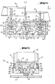
- FIG. 1 there is shown at 15 a mold which has been broken down into two half-molds in order to show on the right part of Figure 1 the mold 15 in the molding position, and on the left part of Figure 1 the same mold 15 in the demolding position.
- the mold 15 can be moved vertically between an upper demolding position (left part of FIG. 1) and a lower molding position in which it is pressed on the board 14 (right part of FIG. 1), by the action of one or more hydraulic cylinders (not shown) whose piston is fixed to the mold and whose cylinder or body is fixed to the chassis.
- these hydraulic jacks no longer serve to support the mold 15 on the vibrating table 12.
- the mold 15 has a substantially parallelepiped shape, two opposite faces of which are respectively provided externally with three hooking lugs 17, of axis of symmetry 18 and distributed evenly over the length of the mold 15.
- the mold 15 has three pairs of legs 17, and we can clearly see in Figure 2 two legs 17 of the same pair.
- the distance separating the two legs 17 of the same pair is slightly greater than the width of the vibrating table 12.
- the hooking lugs 17 extend towards the vibrating table 12 and the length of these is greater than the height of the mold.
- the lower part of each latch 17 has a recess 19 whose role will appear in the following.
- each tab 17 is in fact intended to be clamped in two jaws or claws 21, when the mold 15 is in the molding position.
- six pairs of jaws 21 are provided to grip the lower ends 20 of the six legs 17, and each two pairs of jaws 21 corresponding to each pair of legs 17 is fixed to a support plate 22 by means of joints 23 (figure 2). Consequently, there are three support plates 22 for the three pairs of legs 17, and two pairs of jaws 21 per plate 22.
- Each jaw 21 of the same pair has a projecting part 25 which will engage in the recess 19 of the corresponding tab 17, when the tab-jaw assembly is in the locked position. It should be noted in this connection that the jaw-leg assembly can be replaced by a completely different one. appropriate locking device without departing from the scope of the invention.
- each jaw 21 has a pivot axis 26 which is slightly offset from the axis of symmetry of the jaw. More specifically, it can be said that the pivot axis 26 is located in the lower part of the jaw 21 between the axis of symmetry of the jaw and the axis 18 of the tab 17.
- six stops 27 fixed under the vibrating table 12 cooperate respectively with two jaws 21 belonging to two pairs of jaws associated with the same support plate 22.
- each support plate 22 and the vibrating table 12 is mounted a pair of pneumatic bellows cylinders 30 supplied with compressed air, each bellows cylinder 30 having an upper flange 31 fixed to the vibrating table 12 and a lower flange 32 fixed to the corresponding support plate 22.
- each bellows cylinder 30 having an upper flange 31 fixed to the vibrating table 12 and a lower flange 32 fixed to the corresponding support plate 22.
- each support plate 22 is connected to the base of the frame 11 via a rigid connection and a single pneumatic bellows cylinder 40 supplied with compressed air in opposite directions two bellows cylinders 30 associated with this plate 22.
- a single pneumatic bellows cylinder 40 supplied with compressed air in opposite directions two bellows cylinders 30 associated with this plate 22.
- each bellows cylinder 40 has a lower flange 41 fixed to the base of the chassis 11 and an upper flange 42 fixed to a rigid connection constituted by two parts forming beams 43 and 44, the part 44 being integral with the corresponding support plate 22.
- the axis 45 of each bellows cylinder 40 is located exactly in the middle of the distance separating the axes 46 of the two bellows cylinders 30 of the same pair (FIG. 2).
- the pneumatic bellows cylinders 30 and 40 which vionn to be described and which provide a connection between the vibrating table and the base of the chassis 11, simultaneously constitute means for controlling the opening and closing of the jaws 21, and means for apply the mold 15 on the vibrating table 12 by pulling it down with a predetermined force. More precisely, the bellows jacks 30 and 40 constitute means for pulling or pushing, with respect to the vibrating table 12, the support plates 22 of the jaws 21 when the latter are clamped on the lower end 20 of the lugs 17.
- the concrete is introduced into the mold 15, and the vibration phase of the concrete in the mold, which makes it possible to compact the concrete, begins.
- the mold 15, the board 14 and the vibrating table 12 form a rigid unitary assembly subjected to vibration.
- the vibration is perfectly sinusoidal, having a determined frequency (for example between 50 and 200 Hertz) and an adjustable amplitude (from 0.2-0.3 to 3 min) as a function of the masses put on the unbalance vibrators 13.
- the hydraulic cylinders no longer have the function of keeping the mold compressed on the board and vibrating table assembly; therefore they can have a very flexible attachment which has the advantage of no longer communicating vibrations to the chassis.
- the three bellows cylinders 40 being empty, they prohibit any transmission of vibration from the vibrating table to the base of the chassis 11.
- the three bellows cylinders 40 are inflated and the six bellows cylinders 30 are deflated.
- This has the effect of raising the three plates 22 for supporting the jaws 21, and opening the jaws 21 cooperating with the stops 27.
- the hydraulic cylinders (again supplied) fixed on the one hand to the mold 15 and on the other hand to the chassis, raise the mold 15 - lugs 17 assembly. Consequently, the board 14 supporting the molded concrete products is removed from the press 10 by means appropriate. Another board 14 is then brought to the vibrating table 12, and the molding and demolding operations are carried out as described above.
Abstract
La presse de moulage comporte une table vibrante (12,) une planche (14), un moule (15) déplaçable verticalement entre une position supérieure de démoulage et une position inférieure de moulage, et des moyens (17, 21, 30, 40) pour solidariser, pendant la phase de vibration du béton dans le moule, le moule 15 à la table vibrante (12), la planche (14) étant alors enserrée entre le moule et la table.The molding press comprises a vibrating table (12,) a board (14), a mold (15) movable vertically between an upper demolding position and a lower molding position, and means (17, 21, 30, 40) to secure, during the vibration phase of the concrete in the mold, the mold 15 to the vibrating table (12), the board (14) then being clamped between the mold and the table.
Description
La présente invention se rapporte d'une manière générale aux presses à mouler et concerne plus particulièrement une presse à mouler des produits en béton, tels que par exemple des parpaings, en faisant subir au béton une opération de vibration.The present invention relates generally to molding presses and relates more particularly to a molding press for concrete products, such as for example concrete blocks, by subjecting the concrete to a vibration operation.
On connaît déjà, dans la technique antérieure, des presses à mouler des produits en béton. D'une manière générale, ces presses comprennent un châssis, une table vibrante horizontale supportée par un dispositif vibrant unidirectionnel à action verticale, un système d'amenée de planches une à une sur la table vibrante, un moule déplaçable verticalement grâce à des vérins hydrauliques, chaque vérin ayant son piston fixé au moule et son cylindre fixé au châssis, et un système d'alimentation en béton.In the prior art, presses for molding concrete products are already known. In general, these presses include a chassis, a horizontal vibrating table supported by a unidirectional vibrating device with vertical action, a system of feeding boards one by one on the vibrating table, a mold movable vertically thanks to hydraulic jacks , each cylinder having its piston fixed to the mold and its cylinder fixed to the chassis, and a concrete supply system.
Toutefois, une presse à mouler des produits en béton du type décrit précédemment présente des inconvénients. En effet, pendant la phase de vibration du béton dans le moule, il se produit des chocs de la table vibrante sur la planche, et donc sur le moule appuyé sur ladite planche. Dans ces conditions, les vérins hydrauliques qui servent à appuyer le moule sur la planche, supportent les chocs et les transmettent au châssis. Ainsi, une telle transmission des chocs est bruyante, et provoque des destructions mécaniques. Il en résulte donc que la consommation d'énergie est importante et que le rendement de la presse à mouler est faible.However, a press for molding concrete products of the type described above has drawbacks. In fact, during the vibration phase of the concrete in the mold, shocks from the vibrating table occur on the board, and therefore on the mold supported on said board. Under these conditions, the hydraulic cylinders which serve to support the mold on the board, withstand the shocks and transmit them to the chassis. So a such transmission of shocks is noisy, and causes mechanical destruction. It therefore follows that the energy consumption is high and that the yield of the molding press is low.
La présente invention a pour but de remédier notamment aux inconvénients précités en proposant une presse à mouler des produits en béton qui possède un rendement élevé et qui est d'une très grande fiabilité.The object of the present invention is to remedy the aforementioned drawbacks in particular by proposing a press for molding concrete products which has a high yield and which is very reliable.
A cet effet, l'invention a pour objet une presse de moulage de produits en béton, du type comprenant un châssis, une table vibrante horizontale supportée par un dispositif vibrant unidirectionnel à action verticale, un système d'amenée de planches une à une sur la table vibrante, un moule déplaçable verticalement entre une position supérieure de démoulage et une position inférieure de moulage dans laquelle il est appuyé sur la planche, et un système d'alimentation en béton, caractérisée en ce qu'elle comprend des moyens pour solidariser, pendant la phase de vibration du béton dans le moule, ledit moule à ladite table vibrante, la planche étant alors enserrée entre le moule et la table, de sorte que le moule, la planche et la table forment un ensemble unitaire rigide soumis à la vibration.To this end, the subject of the invention is a press for molding concrete products, of the type comprising a frame, a horizontal vibrating table supported by a unidirectional vibrating device with vertical action, a system for feeding boards one by one on the vibrating table, a mold movable vertically between an upper demolding position and a lower molding position in which it is supported on the board, and a concrete supply system, characterized in that it comprises means for joining, during the vibration phase of the concrete in the mold, said mold to said vibrating table, the board then being sandwiched between the mold and the table, so that the mold, the board and the table form a rigid unitary assembly subjected to vibration .
On comprend ainsi que, pendant la phase de vibration du béton dans le moule, l'emploi des moyens pour solidariser le moule à la table vibrante permet de supprimer toute transmission de chocs de la table vibrante au moule. Par conséquent, il n'y a plus de transmission de chocs au châssis, et d'autre part, les vérins hydrauliques fixés au châssis et au moule ne servent plus à appuyer ce dernier sur la table vibrante. En outre, on réalise une meilleure répartition des vibrations, et un économie de 40 à 50% d'énergie.It is thus understood that, during the vibration phase of the concrete in the mold, the use of means for securing the mold to the vibrating table makes it possible to eliminate any transmission of shocks from the vibrating table to the mold. Consequently, there is no longer any shock transmission to the chassis, and on the other hand, the hydraulic cylinders fixed to the chassis and to the mold are no longer used to press the latter on the table. vibrant. In addition, a better distribution of vibrations is achieved, and a saving of 40 to 50% of energy.
Selon une autre caractéristique de l'invention, les moyens de solidarisation comprennent des pattes solidaires du moule et s'étendant vers la table vibrante, des pinces ou mâchoires destinées à enserrer les extrémités inférieures desdites pattes, des moyens pour commander l'ouverture et la fermeture des mâchoires, ainsi que des moyens pour appliquer ledit moule sur la table vibrante avec une force prédéterminée.According to another characteristic of the invention, the securing means comprise lugs integral with the mold and extending towards the vibrating table, clamps or jaws intended to grip the lower ends of said lugs, means for controlling the opening and the closing the jaws, as well as means for applying said mold to the vibrating table with a predetermined force.
Selon encore une autre caractéristique de l'invention, les derniers moyens précités comprennent des moyens pour tirer ou pousser, par rapport à la table vibrante, des supports des mâchoires quand celles-ci sont serrées sur l'extrémité inférieure des pattes.According to yet another characteristic of the invention, the last aforementioned means comprise means for pulling or pushing, relative to the vibrating table, supports for the jaws when the latter are clamped on the lower end of the legs.
L'invention sera mieux comprise et d'autres buts, caractéristiques, détails et avantages de celle-ci apparaîtront plus clairement au cours de la description explicative qui va suivre faite en référence aux dessins annexés donnés uniquement à titre d'exemple illustrant un mode de réalisation de l'invention et dans lesquels :
- La figure 1 est une vue de face en élévation, avec arrachements partiels, de la presse à mouler selon l'invention, la. partie droite de la figure représentant le moule en position de moulage, et la partie gauche de la figure représentant le moule en position de démoulage.
- La figure 2 est une vue en coupe selon la ligne brisée II-II de la figure 1, le moule étant en position de moulage.
- Figure 1 is a front elevational view, partially broken away, of the molding press according to the invention, la. right part of the figure representing the mold in the molding position, and the left part of the figure representing the mold in the demolding position.
- Figure 2 is a sectional view along the broken line II-II of Figure 1, the mold being in the molding position.
Suivant un exemple de réalisation préféré, et en se reportant aux figures 1 et 2, une presse de moulage 10 de produits en béton, tels que par exemple des parpaings, comprend un châssis 11 (représenté partiellement), et une table vibrante horizontale 12 supportée par un dispositif vibrant unidirectionnel à action verticale constitué par exemple par deux vibrateurs 13 d'un type connu. La presse de moulage 10 est alimentée en planches de bois ou d'autre matériau 14 par un système approprié d'amenée de planches 14 une à une sur la table vibrante 12. D'autre part, la presse 10 est alimentée de façon classique en béton par des moyens appropriés.According to a preferred embodiment, and with reference to Figures 1 and 2, a
Sur la figure 1, on a représenté en 15 un moule qui a été décomposé en deux demi-moules afin de montrer sur la partie droite de la figure 1 le moule 15 en position de moulage, et sur la partie gauche de la figure 1 le même moule 15 en position de démoulage. Bien sùr, la construction du moule 15 permet de mouler un certain nombre de produits en béton à la fois. Le moule 15 est déplaçable verticalement entre une position supérieure de démoulage (partie gauche de la figure 1) et une position inférieure de moulage dans laquelle il est appuyé sur la planche 14 (partie droite de la figure 1), par l'action d'un ou plusieurs vérins hydrauliques (non représentés) dont le piston est fixé au moule et dont le cylindre ou corps est fixé au châssis. Comme on le comprendra par la suite, ces vérins hydrauliques ne servent plus à appuyer le moule 15 sur la table vibrante 12.In Figure 1, there is shown at 15 a mold which has been broken down into two half-molds in order to show on the right part of Figure 1 the
Le moule 15 a une forme sensiblement parallélèpipè- dique, dont deux faces opposées sont respectivement munies extérieurement de trois pattes d'accrochage 17, d'axe de symétrie 18 et réparties d'une façon régulière sur la longueur du moule 15. Ainsi, le moule 15 possède trois paires de pattes 17, et on voit bien sur la figure 2 deux pattes 17 d'une même paire. De plus, comme cela apparaît clairement sur la figure 2, la distance séparant les deux pattes 17 d'une même paire est légèrement supérieure à la largeur de la table vibrante 12. Les pattes d'accrochage 17 s'étendent vers la table vibrante 12 et la longueur de celles-ci est supérieure à la hauteur du moule. En outre, la partie inférieure de chaque patte d'accrochage 17 comporte un évidement 19 dont le rôle apparaîtra dans ce qui suit.The
L'extrémité inférieure 20 de chaque patte 17 est en effet destinée à être enserrée dans deux mâchoires ou griffes 21, lorsque le moule 15 est en position de moulage. Ainsi, six paires de mâchoires 21 sont prévues pour enserrer les extrémités inférieures 20 des six pattes 17, et chaque deux paires de mâchoires 21 correspondant à chaque paire de pattes 17 est fixée à une plaque formant support 22 par l'intermédiaire d'articulations 23 (figure 2). Par conséquent, il existe trois plaques formant supports 22 pour les trois paires de pattes 17, et deux paires de mâchoires 21 par plaque 22.The
Chaque mâchoire 21 d'une même paire comporte une partie en saillie 25 qui viendra s'engager dans l'évidement 19 de la patte 17 correspondante, lorsque l'ensemble patte-mâchoires sera en position de verrouillage. On notera à ce propos que l'ensemble patte-mâchoires peut être remplacé par un tout autre dispositif de verrouillage approprié sans sortir du cadre de l'invention.Each
On comprend déjà que, pendant la phase de vibration du béton dans le moule 15, le moule sera rendu solidaire de la table vibrante 12, la planche 14 étant alors enserrée entre le moule 15 et la table 12, de sorte que le moule 15, la planche 14 et la table 12 formeront un ensemble unitaire rigide soumis à la vibration.It is already understood that, during the vibration phase of the concrete in the
En outre, il faut noter que chaque mâchoire 21 possède un axe de pivotement 26 qui est légèrement décalé par rapport à l'axe de symétrie de la mâchoire. Plus précisément, on peut dire que l'axe de pivotement 26 est situé dans la partie inférieure de la mâchoire 21 comprise entre l'axe de symétrie de la mâchoire et l'axe 18 de la patte 17. De plus, six butées 27 fixées sous la table vibrante 12 coopèrent respectivement avec deux mâchoires 21 appartenant à deux paires de mâchoires associées à une même plaque de support 22.In addition, it should be noted that each
Comme le montre clairement la figure 2, entre chaque plaque de support 22 et la table vibrante 12, est montée une paire de vérins pneumatiques à soufflet 30 alimentés en air comprimé, chaque vérin à soufflet 30 comportant une bride supérieure 31 fixée à la table vibrante 12 et une bride inférieure 32 fixée à la plaque de support 22 correspondante. Au total, il y a donc six vérins pneumatiques à soufflet 30 qui sont montés deux par deux sur une plaque de support 22. On ajoutera que les deux vérins à soufflet 30 d'une même paire sont agencés d'une manière à assurer l'équilibre de la table vibrante 12.As clearly shown in Figure 2, between each
Comme on le voit sur les figures 1 et 2, chaque plaque de support 22 est reliée à la base du châssis 11 par l'intermédiaire d'une liaison rigide et d'un seul vérin pneumatique à soufflet 40 alimenté en air comprimé en sens inverse des deux vérins à soufflet 30 associés à cette plaque 22. Au total, il y a donc trois vérins pneumatiques à soufflet 40, chaque vérin 40 étant assocé à une paire de vérins 30. Plus précisément, chaque vérin à soufflet 40 comporte une bride inférieure 41 fixée à la base du châssis 11 et une bride supérieure 42 fixée à une liaison rigide constituée par deux pièces formant poutres 43 et 44, la pièce 44 étant solidaire de la plaque de support 22 correspondante. On ajoutera que l'axe 45 de chaque vérin à soufflet 40 se trouve exactement au milieu de la distance séparant les axes 46 des deux vérins à soufflet 30 d'une même paire (figure 2).As seen in Figures 1 and 2, each
Les vérins pneumatiques à soufflet 30 et 40 qui vionnent d'être décrits et qui réalisent une liaison entre la table vibrante et la base du chtâssis 11, constituent simultanément des moyens de commande d'ouverture et de fermeture des mâchoires 21, et des moyens pour appliquer le moule 15 sur la table vibrante 12 en le tirant vers le bas avec une force prédéterminer. Plus précisément, les vérins à soufflet 30 et 40 constituent des moyens pour tirer pu pousser, par rapport à la table vibrante 12, les plaques de support 22 des mâchoires 21 quand celles-ci sont serrées sur l'extrémité inférieure 20 des pattes 17.The
Le fonetionnement et la manière d'utiliser la presse à mouler selon l'invention se déduisent de la deseription qui présède et seront expliqués dans ce qui suit.The operation and the manner of using the molding press according to the invention are deduced from the above description and will be explained in this following.
Supposons par exemple que l'on se trouve dans le cas représenté sur la partie gauche de la figure 1, c'est-à-dire que le moule 15 est dans sa position de démoulage, qu'une planche 14 est posée sur la table vibrante 12, que les trois vérins à soufflet 40 sont gonflés, et que les six vérins à soufflet 30 sont dégonflés, les mâchoires 21 étant alors ouvertes.Suppose, for example, that we are in the case shown on the left-hand side of FIG. 1, that is to say that the
Pour passer de la position de démoulage représentée sur la partie gauche de la figure 1 à la position de moulage représentée sur la partie droite de cette même figure, les vérins hydrauliques fixés d'une part sur la partie supérieure du moule 15 et d'autre part sur le châssis abaissent le moule, de sorte que chaque extrémité inférieure 20 de chaque patte 17 pénètre dans l'ouverture des deux mâchoires correspondantes 21. A ce moment là, et simultanément, on dégonfle les trois vérins à soufflet 40 et on gonfle les six vérins à soufflet 30. Ceci a pour effet de faire descendre les trois plaques 22 de supports des mâchoires 21, et de faire basculer les mâchoires 21 coopérant avec les butées 27, de sorte que chaque paire de mâchoires 21 enserre chaque patte 17, par engagement des saillies 25 des mâchoires 21 dans l'évidement 19 des pattes 17. Dans ces conditions, le moule 15 est appliqué sur la table vibrante 12 avec une force prédéterminée. On peut dès lors couper l'alimentation des vérins hydrauliques fixés sur la partie supérieure du moule.To pass from the demolding position represented on the left part of FIG. 1 to the molding position represented on the right part of this same figure, the hydraulic cylinders fixed on the one hand on the upper part of the
Ensuite, le béton est introduit dans le moule 15, et la phase de vibration du béton dans le moule, qui permet de tasser le béton, commence. Pendant cette phase de vibration , le moule 15, la planche 14 et la table vibrante 12 forment un ensemble unitaire rigide soumis à la vibration. On notera à ce propos que la vibration est parfaitement sinusoïdale, ayant une fréquence déterminée (par exemple entre 50 et 200 Hertz) et une amplitude réglable (de 0,2-0,3 à 3 mn) en fonction des masses mises sur le balourd des vibrateurs 13.Then, the concrete is introduced into the
Toujours pendant la phase de vibration du béton dans le moule, il est important de noter que les vérins hydrauliques n'ont plus la fonction de maintenir comprimé le moule sur l'ensemble planche et table vibrante ; de ce fait ils peuvent avoir une fixation très souple qui a pour intérêt de ne plus communiquer de vibrations au châssis. D'autre part, les trois vérins à soufflet 40 étant à vide, ils interdisent toute transmission de vibration de la table vibrante à la base du châssis 11.Still during the vibration phase of the concrete in the mold, it is important to note that the hydraulic cylinders no longer have the function of keeping the mold compressed on the board and vibrating table assembly; therefore they can have a very flexible attachment which has the advantage of no longer communicating vibrations to the chassis. On the other hand, the three
Lorsque le remplissage du moule est exécuté, un dameur vient mettre rigoureusement à hauteur les produits.When the filling of the mold is carried out, a tamper rigorously adjusts the products.
Ensuite, pour le démoulage, et simultanément, on gonfle les trois vérins à soufflet 40 et on dégonfle les six vérins à soufflet 30. Ceci a pour effet de faire monter les trois plaques 22 de supports des mâchoires 21, et d'ouvrir les mâchoires 21 coopérant avec les butées 27. Dans ces conditions, les vérins hydrauliques (de nouveau alimentés) fixés d'une part au moule 15 et d'autre part au châssis, font remonter l'ensemble moule 15 - pattes 17. Dès lors, la planche 14 supportant les produits moulés en béton est évacuée de la presse 10 par des moyens appropriés. Une autre planche 14 est ensuite amenée sur la table vibrante 12, et on procède aux opérations de moulage et de démoulage telles que décrites précédemment.Then, for demolding, and simultaneously, the three
Bien entendu, l'invention n'est nullement limitée au mode de réalisation décrit et représenté qui n'a été donné qu'à titre d'exemple. En particulier, elle comprend tous les moyens constituant des équivalents techniques des moyens décrits, ainsi que leurs combinaisons, si celles-ci sont exécutées suivant son esprit et mises en oeuvre dans le cadre des revendications qui suivent.Of course, the invention is in no way limited to the embodiment described and shown which has been given only by way of example. In particular, it includes all the means constituting technical equivalents of the means described, as well as their combinations, if these are carried out according to the spirit and implemented in the context of the claims which follow.
Claims (7)
Applications Claiming Priority (2)
| Application Number | Priority Date | Filing Date | Title |
|---|---|---|---|
| FR7919461 | 1979-07-27 | ||
| FR7919461A FR2462249A1 (en) | 1979-07-27 | 1979-07-27 | MOLDING PRESS OF CONCRETE PRODUCTS |
Publications (1)
| Publication Number | Publication Date |
|---|---|
| EP0023442A1 true EP0023442A1 (en) | 1981-02-04 |
Family
ID=9228395
Family Applications (1)
| Application Number | Title | Priority Date | Filing Date |
|---|---|---|---|
| EP80401013A Withdrawn EP0023442A1 (en) | 1979-07-27 | 1980-07-03 | Press for moulding concrete products |
Country Status (4)
| Country | Link |
|---|---|
| US (1) | US4332540A (en) |
| EP (1) | EP0023442A1 (en) |
| ES (1) | ES493717A0 (en) |
| FR (1) | FR2462249A1 (en) |
Cited By (2)
| Publication number | Priority date | Publication date | Assignee | Title |
|---|---|---|---|---|
| FR2642355A1 (en) * | 1989-02-01 | 1990-08-03 | Euromat Sa | VIBRATION PRESS FOR MOLDING CONCRETE PRODUCTS |
| CN103580367A (en) * | 2013-11-19 | 2014-02-12 | 无锡建仪仪器机械有限公司 | Buffering device of vibration motor |
Families Citing this family (12)
| Publication number | Priority date | Publication date | Assignee | Title |
|---|---|---|---|---|
| US4531903A (en) * | 1982-07-23 | 1985-07-30 | Sxd Refractories, Inc. | Apparatus for forming particles into shaped articles |
| DE3513388A1 (en) * | 1985-04-15 | 1986-10-16 | Bernd Dipl.-Ing. 7517 Waldbronn Schenk | DEVICE FOR THE PRODUCTION OF PLASTIC MOLDED PARTS, IN PARTICULAR PLASTIC HOLLOW BODIES |
| DE4101593A1 (en) * | 1991-01-21 | 1992-07-23 | Siegfried Gebhart | DEVICE FOR PRODUCING STONES |
| JP2882702B2 (en) * | 1991-05-20 | 1999-04-12 | 株式会社神戸製鋼所 | Mold clamping device for tire vulcanizer |
| ES2154169B1 (en) * | 1998-09-02 | 2001-10-16 | Moncho Luis Celest Castellanos | SYSTEM FOR CONSTRUCTION OF BUILDINGS THROUGH PREFABRICATED PARTS. |
| JP2000127124A (en) * | 1998-10-26 | 2000-05-09 | Shigeru Kobayashi | Apparatus for molding concrete block |
| US7992837B2 (en) * | 2006-12-29 | 2011-08-09 | Lacuna Inc. | Techniques and tools for assembling and disassembling compactable molds and forming building blocks |
| WO2014075677A1 (en) * | 2012-11-13 | 2014-05-22 | Bio Beton System Aps | Method for manufacturing a pervious concrete slab, a concrete slab, and use of the concrete slab |
| DK178024B1 (en) * | 2013-01-10 | 2015-03-23 | Bio Beton System Aps | Process for making a permeable concrete tile, concrete tile, and using the concrete tile |
| CN107053449B (en) * | 2017-06-07 | 2023-03-24 | 中国联合装备集团安阳机械有限公司 | A upset and die block distributor for composite wall panel makes |
| IT201900004988A1 (en) * | 2019-04-03 | 2020-10-03 | O C E M S R L Officina Costruzioni Elettro Mecc | PRESS FOR THE PRODUCTION OF PRODUCTS BY PRESSING A MIX IN A MOLD |
| CN111220436A (en) * | 2020-01-20 | 2020-06-02 | 长安大学 | Detachable concrete test piece vibration molding and integrative equipment of drawing of patterns |
Citations (7)
| Publication number | Priority date | Publication date | Assignee | Title |
|---|---|---|---|---|
| US1595255A (en) * | 1925-11-16 | 1926-08-10 | Hiram A Smith | Vibrating machine |
| GB558907A (en) * | 1942-09-15 | 1944-01-26 | Leon Emile Callebaut | Improved means for securing moulds and mould frames to vibrating tables |
| US2342440A (en) * | 1942-09-23 | 1944-02-22 | Whitsitt William Gambill | Molding apparatus |
| FR995074A (en) * | 1949-07-19 | 1951-11-27 | Prod En Beton Arme Soc Ind De | Method and device for fixing a part on a vibrating table |
| DE1033578B (en) * | 1952-05-23 | 1958-07-03 | Schlosser & Co G M B H | Coupling device for impacted multi-part bodies in stone molding machines |
| FR1506377A (en) * | 1965-09-09 | 1967-12-22 | Injection molding machine | |
| FR2324426A1 (en) * | 1975-09-19 | 1977-04-15 | Reymann Wolfgang | Vibrator blocks for holding shuttering - has clamps moved horizontally into clamping position to avoid vibration induced noise |
Family Cites Families (6)
| Publication number | Priority date | Publication date | Assignee | Title |
|---|---|---|---|---|
| US3530554A (en) * | 1968-03-25 | 1970-09-29 | Superlite Builders Supply Inc | Concrete block machine with pallet locking dogs |
| US3920364A (en) * | 1968-11-19 | 1975-11-18 | Cadogan Rawlinson Christopher | Press |
| US3679340A (en) * | 1969-09-15 | 1972-07-25 | Besser Co | Apparatus for forming building blocks |
| US3660004A (en) * | 1970-04-30 | 1972-05-02 | Besser Co | Pallet clamp |
| DE7437975U (en) * | 1974-11-14 | 1976-05-26 | Bekum Maschinenfabriken Gmbh, 1000 Berlin | BLOW MOLDING UNIT |
| US4238177A (en) * | 1978-04-24 | 1980-12-09 | Crile Eugene E | Molding machine with vibration isolation |
-
1979
- 1979-07-27 FR FR7919461A patent/FR2462249A1/en active Granted
-
1980
- 1980-07-01 US US06/165,032 patent/US4332540A/en not_active Expired - Lifetime
- 1980-07-03 EP EP80401013A patent/EP0023442A1/en not_active Withdrawn
- 1980-07-24 ES ES493717A patent/ES493717A0/en active Granted
Patent Citations (7)
| Publication number | Priority date | Publication date | Assignee | Title |
|---|---|---|---|---|
| US1595255A (en) * | 1925-11-16 | 1926-08-10 | Hiram A Smith | Vibrating machine |
| GB558907A (en) * | 1942-09-15 | 1944-01-26 | Leon Emile Callebaut | Improved means for securing moulds and mould frames to vibrating tables |
| US2342440A (en) * | 1942-09-23 | 1944-02-22 | Whitsitt William Gambill | Molding apparatus |
| FR995074A (en) * | 1949-07-19 | 1951-11-27 | Prod En Beton Arme Soc Ind De | Method and device for fixing a part on a vibrating table |
| DE1033578B (en) * | 1952-05-23 | 1958-07-03 | Schlosser & Co G M B H | Coupling device for impacted multi-part bodies in stone molding machines |
| FR1506377A (en) * | 1965-09-09 | 1967-12-22 | Injection molding machine | |
| FR2324426A1 (en) * | 1975-09-19 | 1977-04-15 | Reymann Wolfgang | Vibrator blocks for holding shuttering - has clamps moved horizontally into clamping position to avoid vibration induced noise |
Cited By (3)
| Publication number | Priority date | Publication date | Assignee | Title |
|---|---|---|---|---|
| FR2642355A1 (en) * | 1989-02-01 | 1990-08-03 | Euromat Sa | VIBRATION PRESS FOR MOLDING CONCRETE PRODUCTS |
| EP0382653A1 (en) * | 1989-02-01 | 1990-08-16 | Euromat S.A. | Vibrating press for moulding concrete products |
| CN103580367A (en) * | 2013-11-19 | 2014-02-12 | 无锡建仪仪器机械有限公司 | Buffering device of vibration motor |
Also Published As
| Publication number | Publication date |
|---|---|
| FR2462249B1 (en) | 1982-12-17 |
| ES8104737A1 (en) | 1981-04-16 |
| FR2462249A1 (en) | 1981-02-13 |
| ES493717A0 (en) | 1981-04-16 |
| US4332540A (en) | 1982-06-01 |
Similar Documents
| Publication | Publication Date | Title |
|---|---|---|
| EP0023442A1 (en) | Press for moulding concrete products | |
| EP0051885B1 (en) | Apparatus for setting and positioning dowels in concrete slabs | |
| FR2727895A1 (en) | METHOD FOR PRODUCING AN OPTICAL LENS OF POLYMERIZABLE SYNTHETIC MATERIAL AND CORRESPONDING APPARATUS | |
| FR3118595A1 (en) | Vibrating machine for the production of construction elements | |
| FR2693278A1 (en) | Device comprising a vibrator fixed to a vehicle for producing seismic vibrations. | |
| EP0382653A1 (en) | Vibrating press for moulding concrete products | |
| EP0202138B1 (en) | Method for making building blocks, means for performing this method and product obtained thereby | |
| FR2534497A1 (en) | DEVICE FOR THE MANUFACTURE OF METAL STRIPS | |
| FR2532580A1 (en) | Vibrating unit for casting elements, in particular concrete elements. | |
| EP0415827B1 (en) | Apparatus for bending glass-sheets | |
| FR2478520A1 (en) | DEVICE FOR THE MANUFACTURE OF PLASTIC OR RUBBER MOLDED PARTS | |
| FR2670696A1 (en) | DESSABLER MACHINE. | |
| FR2901161A1 (en) | Device for stripping metal castings, comprises a device for fixing the metal castings forming an inner reception space, where the metal castings are maintained, hammered and subjected to vibrations | |
| CA1274223A (en) | Method and device for fashioning the bottom of a limp bag derived from a synthetic material | |
| WO2010112681A1 (en) | Locking device for a vibrocompacting device, and compacting device provided with such a locking device | |
| BE902003R (en) | Paving stone laying machine - has adjustable and detachable clamp for handling paving stones in blocks of different sizes | |
| EP2757200B1 (en) | Apparatus for extracting or recessing in the floor an object such as a pile or a tube and corresponding method | |
| EP0209413A1 (en) | Press of the traction type | |
| FR2617886A1 (en) | MUSSEL FOR SALE | |
| WO1985004435A1 (en) | Paving machine | |
| FR2535988A1 (en) | APPARATUS AND METHOD FOR REALIZING A FOUNDRY MOLD | |
| FR2580893A1 (en) | IMPROVED APPARATUS FOR PREPARING FLOORS BY MEANS OF A ROLL UNDER THE TRACTOR AND WITH PRESSURE EXERCISED ON THE GROUND IS ADJUSTABLE BEFORE OR DURING WORK. | |
| EP0086165B1 (en) | Device for supporting, positioning and driving a tubular support during the winding of a web | |
| EP0165189A1 (en) | Device for holding plate materials on the tables of a sawing machine | |
| FR2566014A1 (en) | Manual appliance for the pressing of impregnated fabrics |
Legal Events
| Date | Code | Title | Description |
|---|---|---|---|
| PUAI | Public reference made under article 153(3) epc to a published international application that has entered the european phase |
Free format text: ORIGINAL CODE: 0009012 |
|
| AK | Designated contracting states |
Designated state(s): AT BE CH DE GB IT LU NL SE |
|
| 17P | Request for examination filed |
Effective date: 19810622 |
|
| STAA | Information on the status of an ep patent application or granted ep patent |
Free format text: STATUS: THE APPLICATION IS DEEMED TO BE WITHDRAWN |
|
| 18D | Application deemed to be withdrawn |
Effective date: 19831105 |
|
| RIN1 | Information on inventor provided before grant (corrected) |
Inventor name: VAN DE CAVEYE, YVES HENRI |