EP0086165B1 - Device for supporting, positioning and driving a tubular support during the winding of a web - Google Patents
Device for supporting, positioning and driving a tubular support during the winding of a web Download PDFInfo
- Publication number
- EP0086165B1 EP0086165B1 EP83420011A EP83420011A EP0086165B1 EP 0086165 B1 EP0086165 B1 EP 0086165B1 EP 83420011 A EP83420011 A EP 83420011A EP 83420011 A EP83420011 A EP 83420011A EP 0086165 B1 EP0086165 B1 EP 0086165B1
- Authority
- EP
- European Patent Office
- Prior art keywords
- shell
- pivoting
- cradle
- self
- casing
- Prior art date
- Legal status (The legal status is an assumption and is not a legal conclusion. Google has not performed a legal analysis and makes no representation as to the accuracy of the status listed.)
- Expired
Links
Images


Classifications
-
- B—PERFORMING OPERATIONS; TRANSPORTING
- B65—CONVEYING; PACKING; STORING; HANDLING THIN OR FILAMENTARY MATERIAL
- B65H—HANDLING THIN OR FILAMENTARY MATERIAL, e.g. SHEETS, WEBS, CABLES
- B65H18/00—Winding webs
- B65H18/02—Supporting web roll
- B65H18/04—Interior-supporting
-
- B—PERFORMING OPERATIONS; TRANSPORTING
- B65—CONVEYING; PACKING; STORING; HANDLING THIN OR FILAMENTARY MATERIAL
- B65H—HANDLING THIN OR FILAMENTARY MATERIAL, e.g. SHEETS, WEBS, CABLES
- B65H2301/00—Handling processes for sheets or webs
- B65H2301/40—Type of handling process
- B65H2301/41—Winding, unwinding
- B65H2301/413—Supporting web roll
- B65H2301/4136—Mounting arrangements not otherwise provided for
- B65H2301/41366—Mounting arrangements not otherwise provided for arrangements for mounting and supporting and -preferably- driving the (un)winding shaft
- B65H2301/413665—Mounting arrangements not otherwise provided for arrangements for mounting and supporting and -preferably- driving the (un)winding shaft articulated bearing
Definitions
- the present invention relates to a device for holding, positioning and driving a tubular support around which must be wound a continuous material, in sheet form, delivered at constant speed or not, according to the preamble of claim 1.
- a device for holding, positioning and driving a tubular support around which must be wound a continuous material, in sheet form, delivered at constant speed or not, according to the preamble of claim 1.
- Such a device is known from document FR-A-2 443 406.
- the correct winding of the tissues around a tubular support, support which will be designated in the following description by the expression "tube” is generally carried out either by driving the support tube by tangential contact with at least one driving cylinder or , more generally, by placing the tube on which the material is to be wound on a mandrel actuated directly in rotation (axial drive of said support), this mandrel being generally of square section and being held, at each of its ends, by jaws clamp communicating the rotational movement.
- the drive speed of the support mandrel is modified as the diameter of the winding increases, so as to have a constant linear speed and an equally constant tension.
- the device for holding, positioning and driving a tubular support is characterized in that the mounting of the shell inside the housing is achieved by by means of a link also mounted pivoting about a fixed axis, integral with said lower cradle, the tightening and self-locking means associated with said shell being constituted by a link, the ends of which are mounted by means of axes respectively to the housing and the link, the self-locking being ensured by means of rollers mounted eccentrically on the shell.
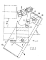
- the jaw according to the invention designated by the general reference (1), and which is capable of being used on any material making it possible to wind a sheet material on a tubular sopport , consists essentially of two elementary parts (2-3) articulated with respect to each other. These two elementary parts (2-3) define between them a cage (4) intended to receive the end of the support tube (5) around which the material is to be wound.
- the part (2) of the jaw will be designated by the expression “lower cradle” while the articulated part (3) will be designated by the expression "clamping shell”.
- the lower cradle (2) is mounted at the end of the driving axis (6), shown only in FIG. 4, to ensure the rotation of the jaw.
- This axis (6) is supported by a bearing (7), a particular embodiment of which will be seen in more detail in the following description, and is rotated by any suitable means, for example by a motor (not shown ).
- the shell (3) is pivotally mounted on the lower cradle (2) and comprises means ensuring the tightening and the self-locking of the end of the support tube during winding.
- the retention and articulation of the shell (3) relative to the lower cradle (2) is obtained by means of a housing (8) mounted on the cradle (2) via 'a pivot axis (9).
- This case has an open face (10) and a window (11) on its rear face, allowing it to pivot relative to the fixed lower cradle (2).
- the mounting of the upper shell (3) inside this box (8) is carried out by means of a connecting rod (12) also pivotally mounted around a fixed axis (13) also integral with the lower cradle.
- the cage (4) intended to receive the ends of the tube (5) consists of two circular sectors (or other shape) complementary (14) and (15), one (14 ) formed on the cradle (2), the other (15) on the shell (3).
- the internal faces of these spans (14) and (15) are coated with a layer of protective felt material for example.
- the shell (3) comprises means ensuring the tightening and self-locking of the support tube during the winding of the material.
- clamping and self-locking means are constituted, in this embodiment, by the rod (16) whose ends are mounted, by means of pins (17-18), respectively to the housing (8) and to the link (12).
- the self-locking is ensured by means of rollers (19-20) mounted eccentrically on the shell (3) which, in the closed position, come to bear on the periphery of the support tube (5).
- a clamping force adjustment system constituted for example by a threaded rod (21) mounted on the shell (3), rod which cooperates with a nut (22) integral with the link (12), can be envisaged in order to better define the respective positions between the cradle (2) and said shell (3).
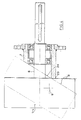
- the jaw according to the invention is mounted on the drive shaft (6) by means of a bearing (7) of particular shape which, automatically , allows to position said jaw so that the lower cradle (2) is necessarily in the low position when it is desired to set up (or remove) the support tube.
- the bearing (7) has an inclined front face whose base (23) serves as a fulcrum for the cradle (2), as well as the housing (8) when it is in the closed position.
- the cutaway (24) of this bearing makes it possible to define the position of the housing (8) in the open position and consequently, to limit the pivoting of the shell (3) to the desired value allowing the positioning and removal of the tube (5).
- the opening and closing can only be carried out with the cradle (2) in the low position.
- Such a bearing shape also makes it possible to ensure very high operating safety of the assembly, taking into account that if, by mistake, the assembly is caused to rotate while the jaw is open, the cutaway will have tendency to automatically cause the shell to close.
- FIGS. 5, 6 and 7 illustrate a variant in accordance with the invention making it possible to use a single device for tubes of variable section, for example of circular, hexagonal, square shape (references 5a, 5b, 5c to Figure 5) and this, at the cost of a simple and quick adaptation to achieve.
- the handling of the assembly is facilitated by providing a peripheral flywheel (31) at the rear of the housing (8).
- the immobilization of the tube and especially in the case of cardboard tubes can be improved by providing on the internal surface of the lower cradle (2) small pins which penetrate inside said tube without however the deteriorate.
- the facing faces (32-33) of the cradle (2) and of the shell (3) may not be smooth and have complementary raised surfaces which interpenetrate (see FIG. 6) and avoid any relative displacement of two elements with respect to each other.
Abstract
Description
La présente invention concerne un dispositif pour le maintien, le positionnement et l'entraînement d'un support tubulaire autour duquel doit être enroulé un matériau continu, en forme de feuille, débité à vitesse constante ou non, selon le préambule de la revendication 1. Un tel dispositif est connu du document FR-A-2 443 406.The present invention relates to a device for holding, positioning and driving a tubular support around which must be wound a continuous material, in sheet form, delivered at constant speed or not, according to the preamble of
Elle a trait plus particulièrement à un dispositif enrouleur perfectionné de matière textile, telle que par exemple tissus, tricots ... Dans la suite de la description, l'invention sera décrite pour cette application particulière, mais il est évident que cela n'est pas limitatif et qu'elle peut également convenir pour enrouler toute forme de matériau se présentant sous forme de bandes continues, et qui doivent être enroulées sur un support tubulaire lors des différents stades de leur fabrication, par exemple à la sortie du dispositif sur lequel ils sont produits ou lors des traitements qu'ils subissent.It relates more particularly to an improved winding device of textile material, such as for example fabrics, knits ... In the following description, the invention will be described for this particular application, but it is obvious that this is not not limiting and that it may also be suitable for winding any form of material in the form of continuous strips, which must be wound on a tubular support during the various stages of their manufacture, for example at the outlet of the device on which they are produced or during the treatments they undergo.
L'enroulement correct des tissus autour d'un support tubulaire, support qui sera désigné dans la suite de la description par l'expression »tube« est en général réalisé soit en entraînant le tube support par contact tangentiel avec au moins un cylindre moteur soit, plus généralement, en disposant le tube sur lequel la matière doit être enroulée sur un mandrin actionné directement en rotation (entraînement axial dudit support), ce mandrin étant en général de section carrée et étant maintenu, à chacune de ses extrémités, par des mors de serrage communiquant le mouvement de rotation. Avantageusement, la vitesse d'entrathement du mandrin support est modifiée au fur et à mesure de l'augmentation du diamètre de l'enroulement, de manière à avoir une vitesse linéaire constante et une tension également constante.The correct winding of the tissues around a tubular support, support which will be designated in the following description by the expression "tube" is generally carried out either by driving the support tube by tangential contact with at least one driving cylinder or , more generally, by placing the tube on which the material is to be wound on a mandrel actuated directly in rotation (axial drive of said support), this mandrel being generally of square section and being held, at each of its ends, by jaws clamp communicating the rotational movement. Advantageously, the drive speed of the support mandrel is modified as the diameter of the winding increases, so as to have a constant linear speed and an equally constant tension.
L'un des problèmes qui se pose pour la mise en œuvre d'une telle technique, est celui de la mise en place du mandrin support à l'intérieur du tube ainsi que son enlèvement à la fin de l'opération d'enroulement. De plus, la transmission du mouvement de rotation entre le mors moteur et le mandrin support provoque en général une usure rapide de ces éléments, compte-tenu du fait que cette transmission est obtenue par contact avec les extrémités du mandrin qui sont de section carrée.One of the problems which arises for the implementation of such a technique is that of the positioning of the support mandrel inside the tube as well as its removal at the end of the winding operation. In addition, the transmission of the rotational movement between the motor jaw and the support mandrel generally causes rapid wear of these elements, taking into account the fact that this transmission is obtained by contact with the ends of the mandrel which are of square section.
Pour faciliter la mise en place et l'enlèvement de l'enroulement, il a été envisagé, ainsi que cela ressort du document FR-A-2 443 406, d'utiliser des mors réalisés en deux parties, pivotantes l'une par rapport à l'autre, de telle sorte que les extrémités du mandrin puissent être complètement dégagées lors de ces opérations. Ces dispositifs n'éliminent cependant pas les inconvénients qui découlent de l'utilisation d'un mandrin support.To facilitate the installation and removal of the winding, it has been envisaged, as is apparent from document FR-A-2 443 406, to use jaws made in two parts, pivoting one with respect to to the other, so that the ends of the mandrel can be completely released during these operations. These devices do not however eliminate the drawbacks which arise from the use of a support mandrel.
Or on a trouvé, et c'est ce qui fait l'objet de la présente invention, un perfectionnement aux mors servant au maintien, au positionnement et à l'entranement des supports tubulaires destinés à recevoir une matière en feuille, tissus notamment, qui surmonte les inconvénients des solutions antérieures.However, we have found, and this is what is the subject of the present invention, an improvement to the jaws serving to hold, position and drive the tubular supports intended to receive sheet material, in particular fabrics, which overcomes the disadvantages of previous solutions.
Conformément à l'invention, le dispositif pour le maintien, le positionnement et l'entrainement d'un support tubulaire selon le préambule de la revendication 1 est caractérisé par le fait que le montage de la coquille à l'intérieur du boitier est réalisé par l'intermédiaire d'une biellette montée également pivotante autour d'un axe fixe, solidaire dudit berceau inférieur, les moyens de serrage et d'autoblocage associés à ladite coquille étant constitués par une biellette dont les extrémités sont montées au moyen d'axes respectivement au boitier et à la biellette, l'auto-blocage étant assuré au moyen de galets montés de manière excentrique sur la coquille.According to the invention, the device for holding, positioning and driving a tubular support according to the preamble of
L'invention et les avantages qu'elle apporte seront cependant mieux compris grâce aux exemples de réalisation donnés ci-après à titre indicatif mais non limitatif et qui sont illustrés par les schémas annexés dans lesquels:
- - les figures 1 et 2 sont respectivement des vues de face et en coupe selon l'ace X d'un mors réalisé conformément à l'invention en position fermée,
- - la figure 3 est une vue en coupe montrant un tel mors en position ouverte lors de l'enlèvement ou de la mise en place des tubes support,
- - la figure 4 est une vue schématique en coupe montrant un mode particulier de montage d'un mors conforme à l'invention sur le bâti d'une machine d'enroulement,
- - les figures 5, 6 et 7 sont des vues similaires aux figures 1, 2 et 3 montrant une variante d'un tel dispositif adaptable pour des supports tubulaires de section variable, par exemple circulaire, hexagonale, carrée.
- FIGS. 1 and 2 are respectively front and sectional views along the area X of a jaw produced in accordance with the invention in the closed position,
- FIG. 3 is a sectional view showing such a jaw in the open position when the support tubes are removed or put in place,
- FIG. 4 is a schematic sectional view showing a particular method of mounting a jaw according to the invention on the frame of a winding machine,
- - Figures 5, 6 and 7 are views similar to Figures 1, 2 and 3 showing a variant of such a device adaptable for tubular supports of variable section, for example circular, hexagonal, square.
Dans la suite de la description, les mêmes références seront utilisées pour désigner les mêmes éléments des deux modes de réalisation exemplifiés.In the following description, the same references will be used to designate the same elements of the two exemplified embodiments.
Si l'on se reporte aux figures annexées, le mors conforme à l'invention, désigné par la référence générale (1), et qui est susceptible d'être utilisé sur tout matériel permettant d'enrouler une matière en feuille sur un sopport tubulaire, se compose essentiellement de deux parties élémentaires (2-3) articulées l'une par rapport à l'autre. Ces deux parties élémentaires (2-3) définissent entre elles une cage (4) destinée à recevoir l'extrémité du tube support (5) autour duquel la matière doit être enroulée. Dans la suite de la description, la partie (2) du mors sera désignée par l'expression »berceau inférieur« alors que la partie articulée (3) sera désignée par l'expression »coquille de serrage«.If reference is made to the appended figures, the jaw according to the invention, designated by the general reference (1), and which is capable of being used on any material making it possible to wind a sheet material on a tubular sopport , consists essentially of two elementary parts (2-3) articulated with respect to each other. These two elementary parts (2-3) define between them a cage (4) intended to receive the end of the support tube (5) around which the material is to be wound. In the following description, the part (2) of the jaw will be designated by the expression "lower cradle" while the articulated part (3) will be designated by the expression "clamping shell".
Dans ce mode de réalisation, le berceau inférieur (2) est monté à l'extrémité de l'axe d'eritrai- nement (6), représenté uniquement à la figure 4, permettant d'assurer la rotation du mors. Cet axe (6) est supporté par un palier (7), dont une forme de réalisation particulière sera vue plus en détail dans la suite de la description, et est entraîné en rotation par tout moyen approprié, par exemple par un moteur (non représenté).In this embodiment, the lower cradle (2) is mounted at the end of the driving axis (6), shown only in FIG. 4, to ensure the rotation of the jaw. This axis (6) is supported by a bearing (7), a particular embodiment of which will be seen in more detail in the following description, and is rotated by any suitable means, for example by a motor (not shown ).
Conformément à l'invention, la coquille (3) est montée pivotante sur le berceau inférieur (2) et comporte des moyens assurant le serrage et l'auto-blocage de l'extrémité du tube support lors de l'enroulement. Dans le mode de réalisation illustré, le maintien et l'articulation de la coquille (3) par rapport au berceau inférieur (2) est obtenu au moyen d'un boitier (8) monté sur le berceau (2) par l'intermédiaire d'un axe de pivotement (9). Ce boitier présente une face ouverte (10) ainsi qu'une fenêtre (11), sur sa face arrière, permettant d'assurer son pivotement par rapport au berceau inférieur fixe (2). Le montage de la coquille supérieure (3) à l'intérieur de ce boitier (8) est réalisé par l'intermédaire d'une biellette (12) montée également pivotante autour d'un axe fixe (13) solidaire également du berceau inférieur.According to the invention, the shell (3) is pivotally mounted on the lower cradle (2) and comprises means ensuring the tightening and the self-locking of the end of the support tube during winding. In the illustrated embodiment, the retention and articulation of the shell (3) relative to the lower cradle (2) is obtained by means of a housing (8) mounted on the cradle (2) via 'a pivot axis (9). This case has an open face (10) and a window (11) on its rear face, allowing it to pivot relative to the fixed lower cradle (2). The mounting of the upper shell (3) inside this box (8) is carried out by means of a connecting rod (12) also pivotally mounted around a fixed axis (13) also integral with the lower cradle.
Ainsi que cela ressort clairement de la figure 1, la cage (4) destinée à recevoir les extrémités du tube (5) est constituée de deux secteurs circulaires (ou autre forme) complémentaires (14) et (15), l'un (14) formé sur le berceau (2), l'autre (15) sur la coquille (3). De préference, les faces internes de ces portées (14) et (15) sont revêtues d'une couche de matière protectrice feutre par exemple.As is clear from FIG. 1, the cage (4) intended to receive the ends of the tube (5) consists of two circular sectors (or other shape) complementary (14) and (15), one (14 ) formed on the cradle (2), the other (15) on the shell (3). Preferably, the internal faces of these spans (14) and (15) are coated with a layer of protective felt material for example.
Comme dit précédemment, la coquille (3) comporte des moyens assurant le serrage et l'auto-blocage du tube support lors de l'enroulement de la matière. Ces moyens de serrage et d'auto-blocage sont constitués, dans cet exemple de réalisation, par la biellette (16) dont les extrémités sont montées, au moyen d'axes (17-18), respectivement au boitier (8) et à la biellette (12). L'auto-blocage est assuré au moyen de galets (19-20) montés de manière excentrique sur la coquille (3) qui, en position fermée, viennent prendre appui à la périphérie du tube support (5). Par ailleurs, un système de réglage de la force de serrage, constitué par exemple par une tige filetée (21) montée sur la coquille (3), tige qui coopère avec un écrou (22) solidaire de la biellette (12), peut être envisagé afin de mieux définir les positions respectives entre le berceau (2) et ladite coquille (3).As said previously, the shell (3) comprises means ensuring the tightening and self-locking of the support tube during the winding of the material. These clamping and self-locking means are constituted, in this embodiment, by the rod (16) whose ends are mounted, by means of pins (17-18), respectively to the housing (8) and to the link (12). The self-locking is ensured by means of rollers (19-20) mounted eccentrically on the shell (3) which, in the closed position, come to bear on the periphery of the support tube (5). Furthermore, a clamping force adjustment system, constituted for example by a threaded rod (21) mounted on the shell (3), rod which cooperates with a nut (22) integral with the link (12), can be envisaged in order to better define the respective positions between the cradle (2) and said shell (3).
La mise en oeuvre d'un tel dispositif est la suivante. Lors de la mise en place (ou de l'enlèvement) du tube support, le mors est en position ouverte tel que représenté à la figure 3. Pour obtenir cette position, il suffit d'exercer une force F2 sur le boitier (8), ce qui provoque sa rotation et, par suite le pivotement de la coquille (3) en arrière. Ce pivotement permet de dégager complètement le dessus du berceau (2) et par suite, le tube support peut être mis en place (ou enlevé) de manière aisée. En fonctionnement normal, c'est-à-dire lorsque la matière est enroulée, la coquille (3) est ramenée en postion fermée tel que cela est représenté aux figures 1 et 2. Pour cela, on exerce une force F, à la partie supérieure du boitier (8), ce qui provoque son pivotement autour de l'axe (9). Lorsque la biellette (16) se trouve dans le prolongement de l'axe A (voir figure 2), les deux portées (14-15) enserrent l'extrémité du tube (5) et assurent son pincement. Pour assurer le blocage définitif, on exerce une pression supplémentaire permettant de déplacer la biellette (12) de telle sorte que son axe (18) soit situé dans le plan B (voir figure 2) en avant du plan A. Par suite, les forces qui s'exercent lors de l'enroulement et qui auraient tendance à provoquer l'ouverture du dispositif, auront une action telle qu'elles tendront au contraire à assurer un pincement plus important de l'extrémité du tube (5). Lors de la fermeture, bien entendu, les deux excentriques (19-20) viennent en appui à la périphérie du tube (5). Lorsque l'entraînement est réalisé, ces deux excentriques ont tendance à venir plaquer contre la périphérie du tube et assurent donc son blocage de manière efficace.The implementation of such a device is as follows. When fitting (or removing) the support tube, the jaw is in the open position as shown in FIG. 3. To obtain this position, it suffices to exert a force F 2 on the housing (8 ), which causes its rotation and, consequently, the pivoting of the shell (3) backwards. This pivoting makes it possible to completely release the top of the cradle (2) and as a result, the support tube can be put in place (or removed) easily. In normal operation, that is to say when the material is wound, the shell (3) is brought back into the closed position as shown in FIGS. 1 and 2. For this, a force F is exerted on the part upper case (8), which causes it to pivot about the axis (9). When the link (16) is in the extension of the axis A (see Figure 2), the two bearing surfaces (14-15) enclose the end of the tube (5) and ensure its nipping. To ensure final blocking, an additional pressure is applied to move the link (12) so that its axis (18) is located in the plane B (see Figure 2) in front of the plane A. As a result, the forces which are exerted during the winding and which would tend to cause the opening of the device, will have an action such that they will on the contrary tend to ensure a greater pinching of the end of the tube (5). When closing, of course, the two eccentrics (19-20) come to bear on the periphery of the tube (5). When the drive is performed, these two eccentrics tend to press against the periphery of the tube and therefore ensure its blocking effectively.
Par ailleurs, dans le mode de réalisation illustré à la figure 4, le mors conforme à l'invention est monté sur l'axe d'entraînement (6) au moyen d'un palier (7) de forme particulière qui, de manière automatique, permet de positionner ledit mors de telle sorte que le berceau inférieur (2) soit obligatoirement en position basse lorsque l'on désire mettre en place (ou enlever) le tube support. Pour cela, le palier (7) présente une face avant inclinée dont la base (23) sert de point d'appui au berceau (2), ainsi qu'au boitier (8) lorsqu'il est en position fermée. Le pan coupé (24) de ce palier permet de définir la position du boitier (8) en position ouverte et par suite, de limiter le pivotement de la coquille (3) à la valeur souhaitée permettant la mise en place et l'enlèvement du tube (5). Compte-tenu de cette forme de réalisation particulière, l'ouverture et la fermeture ne peut être réalisée qu'avec le berceau (2) en position basse. Une telle forme de palier permet également d'assurer une très grande sécurité de fonctionnement de l'ensemble compte-tenu du fait que si, par mégarde, on provoque la rotation de l'ensemble alors que le mors est ouvert, le pan coupé aura tendance à provoquer automatiquement la fermeture de la coquille.Furthermore, in the embodiment illustrated in Figure 4, the jaw according to the invention is mounted on the drive shaft (6) by means of a bearing (7) of particular shape which, automatically , allows to position said jaw so that the lower cradle (2) is necessarily in the low position when it is desired to set up (or remove) the support tube. For this, the bearing (7) has an inclined front face whose base (23) serves as a fulcrum for the cradle (2), as well as the housing (8) when it is in the closed position. The cutaway (24) of this bearing makes it possible to define the position of the housing (8) in the open position and consequently, to limit the pivoting of the shell (3) to the desired value allowing the positioning and removal of the tube (5). Given this particular embodiment, the opening and closing can only be carried out with the cradle (2) in the low position. Such a bearing shape also makes it possible to ensure very high operating safety of the assembly, taking into account that if, by mistake, the assembly is caused to rotate while the jaw is open, the cutaway will have tendency to automatically cause the shell to close.
L'exemple qui précède montre bien les avantages apportés par la présente invention, notamment le fait que grâce à un tel type de mors, il est possible d'entraner, sans mandrin support, tout tube pouvent servir à l'enroulement de matière en feuille. Bien entendu, ces tubes pourront se présenter sous différentes formes, être pleins ou creux. Ainsi, les figures 5, 6 et 7 illustrent une variante conforme à l'invention permettant d'utiliser un seul et même dispositif pour des tubes de section variable, par exemple de forme circulaire, hexagonale, carrée (références 5a, 5b, 5c à la figure 5) et ce, au prix d'une adaptation simple et rapide à réaliser. Cela est obtenu en réalisant le berceau inférieur (2) non pas en une pièce unique comme dans l'exemple illustré aux figures 1, 2 et 3, mais en prévoyant un élément rapporté (2a) formant le berceau proprement dit et dont la forme est adaptée en fonction de la forme du tube à serrer. Cette partie (2a) est fixée par un système à boulon et goupille (30) conventionnels. En fonction du tube à serrer la partie articulée (3) (coquille de serrage) aura une forme correspondante.The above example clearly shows the advantages provided by the present invention, in particular the fact that, thanks to such a type of jaw, it is possible to drive, without support mandrel, any tube can be used for winding sheet material. . Of course, these tubes can be in different forms, be full or hollow. Thus, FIGS. 5, 6 and 7 illustrate a variant in accordance with the invention making it possible to use a single device for tubes of variable section, for example of circular, hexagonal, square shape (references 5a, 5b, 5c to Figure 5) and this, at the cost of a simple and quick adaptation to achieve. This is achieved by making the lower cradle (2) not in a single piece as in the example illustrated in
Par ailleurs, dans ce mode de réalisation, la manipulation de l'ensemble est facilitée en prévoyant un volant périphérique (31) à l'arrière du boitier (8). De plus, l'immobilisation du tube et notamment lorsqu'il s'agit de tubes en carton, peut être améliorée en prévoyant sur la surface interne du berceau inférieur (2) de petits picots qui pénètrent à l'intérieur dudit tube sans cependant le détériorer. Enfin, les faces en regard (32-33) du berceau (2) et de la coquille (3) peuvent ne pas être lisses et présenter des surfaces en relief complémentaires qui s'interpénètrent (voir figure 6) et évitent tout déplacement relatif de deux éléments l'un par rapport à l'autre.Furthermore, in this embodiment, the handling of the assembly is facilitated by providing a peripheral flywheel (31) at the rear of the housing (8). In addition, the immobilization of the tube and especially in the case of cardboard tubes, can be improved by providing on the internal surface of the lower cradle (2) small pins which penetrate inside said tube without however the deteriorate. Finally, the facing faces (32-33) of the cradle (2) and of the shell (3) may not be smooth and have complementary raised surfaces which interpenetrate (see FIG. 6) and avoid any relative displacement of two elements with respect to each other.
Bien entendu, l'invention n'est pas limitée aux exemples de réalisation décrits précédemment mais elle en couvre toutes les variantes réalisées dans le même esprit. Ainsi, il pourrait être envisagé d'associer aux galets assurant l'auto-blocage des butées d'arrêt destinées à limiter leur pénétration dans le tube support, ce qui permet de leur faire jouer également le rôle de limitateur de couple.Of course, the invention is not limited to the embodiments described above but it covers all the variants produced in the same spirit. Thus, it could be envisaged to associate with the rollers ensuring the self-locking of the abutments intended to limit their penetration into the support tube, which allows them to also play the role of torque limiter.
Par rapport aux solutions antérieures, un tel dispositif permet non seulement d'éviter l'utilisation de mandrin support interne, mais par ailleurs, assure une très grande sécurité de fonctionnement tout en étant d'une utilisation particulièrement simple et efficace.Compared to previous solutions, such a device makes it possible not only to avoid the use of an internal support mandrel, but moreover, ensures very high operating safety while being of particularly simple and effective use.
Claims (5)
Priority Applications (1)
| Application Number | Priority Date | Filing Date | Title |
|---|---|---|---|
| AT83420011T ATE17110T1 (en) | 1982-02-04 | 1983-01-25 | DEVICE FOR HOLDING, POSITIONING AND DRIVING THE WINDING SHAFT WHEN WINDING WEBS. |
Applications Claiming Priority (2)
| Application Number | Priority Date | Filing Date | Title |
|---|---|---|---|
| FR8201951 | 1982-02-04 | ||
| FR8201951A FR2520709A1 (en) | 1982-02-04 | 1982-02-04 | DEVICE FOR MAINTAINING, POSITIONING AND DRIVING A TUBULAR SUPPORT WHEN WINDING SHEET MATERIAL |
Publications (2)
| Publication Number | Publication Date |
|---|---|
| EP0086165A1 EP0086165A1 (en) | 1983-08-17 |
| EP0086165B1 true EP0086165B1 (en) | 1985-12-27 |
Family
ID=9270742
Family Applications (1)
| Application Number | Title | Priority Date | Filing Date |
|---|---|---|---|
| EP83420011A Expired EP0086165B1 (en) | 1982-02-04 | 1983-01-25 | Device for supporting, positioning and driving a tubular support during the winding of a web |
Country Status (4)
| Country | Link |
|---|---|
| EP (1) | EP0086165B1 (en) |
| AT (1) | ATE17110T1 (en) |
| DE (1) | DE3361579D1 (en) |
| FR (1) | FR2520709A1 (en) |
Cited By (1)
| Publication number | Priority date | Publication date | Assignee | Title |
|---|---|---|---|---|
| EP0194356A1 (en) * | 1985-03-14 | 1986-09-17 | Ludwig Boschert GmbH & Co. KG Maschinen- und Apparatebau | Hinged bearing |
Family Cites Families (2)
| Publication number | Priority date | Publication date | Assignee | Title |
|---|---|---|---|---|
| DE917592C (en) * | 1952-08-15 | 1954-09-06 | Faerberei & Appretur Schutster | Device for coupling winding bars |
| DE2852510C2 (en) * | 1978-12-05 | 1983-10-27 | Kunz Maschinen- und Apparatebau GmbH, 7850 Lörrach | Device for coupling winding bars |
-
1982
- 1982-02-04 FR FR8201951A patent/FR2520709A1/en active Granted
-
1983
- 1983-01-25 DE DE8383420011T patent/DE3361579D1/en not_active Expired
- 1983-01-25 EP EP83420011A patent/EP0086165B1/en not_active Expired
- 1983-01-25 AT AT83420011T patent/ATE17110T1/en not_active IP Right Cessation
Cited By (1)
| Publication number | Priority date | Publication date | Assignee | Title |
|---|---|---|---|---|
| EP0194356A1 (en) * | 1985-03-14 | 1986-09-17 | Ludwig Boschert GmbH & Co. KG Maschinen- und Apparatebau | Hinged bearing |
Also Published As
| Publication number | Publication date |
|---|---|
| DE3361579D1 (en) | 1986-02-06 |
| EP0086165A1 (en) | 1983-08-17 |
| ATE17110T1 (en) | 1986-01-15 |
| FR2520709A1 (en) | 1983-08-05 |
| FR2520709B1 (en) | 1984-03-16 |
Similar Documents
| Publication | Publication Date | Title |
|---|---|---|
| EP0500405B1 (en) | Cramping and grasping device | |
| FR2543097A1 (en) | Manually controlled hydraulic brake for a bicycle, and braking method | |
| EP0810944A1 (en) | Rapid locking pin for use on a cycle | |
| FR2644542A1 (en) | TENSIONING DEVICE WITH SPRING ADJUSTMENT | |
| EP0665926B1 (en) | Mechanically operated drum brake | |
| EP1469766B1 (en) | Device for controlling and regulating the pressure of a roll of material in an automatic-cutting dispenser | |
| FR2745524A1 (en) | DEVICE FOR FIXING A COATING MEMBER ON A CYLINDER OF A PRINTING GROUP | |
| EP1054826A1 (en) | Transfer device for hollow body comprising a neck | |
| FR2771319A1 (en) | Clamp for tubular pieces with radially sliding jaws | |
| EP0385818B1 (en) | Machine to cut and fold a printed paper web | |
| EP0330551B1 (en) | Automatic article gripper | |
| EP0267112A1 (en) | Installation for metal extrusion | |
| EP0928682B1 (en) | Device for the mecanical treatment of paper which has an improved support for a roller and method for exchanging the roller in such a device | |
| EP0086165B1 (en) | Device for supporting, positioning and driving a tubular support during the winding of a web | |
| FR3023276A1 (en) | DEVICE FOR HALKING A TUBULAR OBJECT OF LARGE LENGTH | |
| EP0596808B1 (en) | Clamping head | |
| EP0045272B1 (en) | Blocking device for a workpiece during a manufacturing operation such as drilling | |
| FR2745805A1 (en) | CONTINUOUS COILING MACHINE WITH AT LEAST ONE MEANS FOR DEROULING TWO TWO-PIECE OR COAXIAL COILS SIMULTANEOUSLY | |
| FR2604856A1 (en) | Large baler with wrapping device | |
| EP0323364A1 (en) | Work head for a tree-processing machine | |
| FR2629448A1 (en) | APPARATUS FOR CUTTING A PIECE OF A GLASS OR CERAMIC TYPE OF MATERIAL ALONG AN INCORPORATED LINE | |
| LU86110A1 (en) | ACTUATOR FOR THE MOVEMENT OF A TOOL AND CARCASS TRANSFER DEVICE FOR PNEUMATIC TIRES USING THE SAME | |
| EP0394104A1 (en) | Clamp device with self-clamping jaws, in particular for a hydraulic linear winch | |
| CH642269A5 (en) | SKI BRAKE. | |
| FR2521966A1 (en) | DEVICE FOR THE WINDING OF TEXTILE MATERIALS COMPRISING A BRAKE MEMBER FOR THE IMMOBILIZATION OF THE WINDING AT THE END OF OPERATION |
Legal Events
| Date | Code | Title | Description |
|---|---|---|---|
| PUAI | Public reference made under article 153(3) epc to a published international application that has entered the european phase |
Free format text: ORIGINAL CODE: 0009012 |
|
| AK | Designated contracting states |
Designated state(s): AT BE CH DE GB IT LI NL |
|
| 17P | Request for examination filed |
Effective date: 19840123 |
|
| ITF | It: translation for a ep patent filed |
Owner name: JACOBACCI & PERANI S.P.A. |
|
| GRAA | (expected) grant |
Free format text: ORIGINAL CODE: 0009210 |
|
| AK | Designated contracting states |
Designated state(s): AT BE CH DE GB IT LI NL |
|
| PG25 | Lapsed in a contracting state [announced via postgrant information from national office to epo] |
Ref country code: NL Effective date: 19851227 Ref country code: AT Effective date: 19851227 |
|
| REF | Corresponds to: |
Ref document number: 17110 Country of ref document: AT Date of ref document: 19860115 Kind code of ref document: T |
|
| REF | Corresponds to: |
Ref document number: 3361579 Country of ref document: DE Date of ref document: 19860206 |
|
| NLV1 | Nl: lapsed or annulled due to failure to fulfill the requirements of art. 29p and 29m of the patents act | ||
| PLBE | No opposition filed within time limit |
Free format text: ORIGINAL CODE: 0009261 |
|
| STAA | Information on the status of an ep patent application or granted ep patent |
Free format text: STATUS: NO OPPOSITION FILED WITHIN TIME LIMIT |
|
| 26N | No opposition filed | ||
| PG25 | Lapsed in a contracting state [announced via postgrant information from national office to epo] |
Ref country code: LI Effective date: 19870131 Ref country code: CH Effective date: 19870131 |
|
| BERE | Be: lapsed |
Owner name: CHOGNARD JEAN-LOUIS Effective date: 19870131 |
|
| GBPC | Gb: european patent ceased through non-payment of renewal fee | ||
| REG | Reference to a national code |
Ref country code: CH Ref legal event code: PL |
|
| PG25 | Lapsed in a contracting state [announced via postgrant information from national office to epo] |
Ref country code: DE Effective date: 19871001 |
|
| PG25 | Lapsed in a contracting state [announced via postgrant information from national office to epo] |
Ref country code: GB Effective date: 19881122 |
|
| PG25 | Lapsed in a contracting state [announced via postgrant information from national office to epo] |
Ref country code: BE Effective date: 19890131 |