EP0022035B1 - Procédé et dispositif de dépollution dans une installation de fabrication d'un matelas de fibres - Google Patents
Procédé et dispositif de dépollution dans une installation de fabrication d'un matelas de fibres Download PDFInfo
- Publication number
- EP0022035B1 EP0022035B1 EP80400998A EP80400998A EP0022035B1 EP 0022035 B1 EP0022035 B1 EP 0022035B1 EP 80400998 A EP80400998 A EP 80400998A EP 80400998 A EP80400998 A EP 80400998A EP 0022035 B1 EP0022035 B1 EP 0022035B1
- Authority
- EP
- European Patent Office
- Prior art keywords
- venturis
- enclosure
- boxes
- walls
- spraying
- Prior art date
- Legal status (The legal status is an assumption and is not a legal conclusion. Google has not performed a legal analysis and makes no representation as to the accuracy of the status listed.)
- Expired
Links
- 238000000034 method Methods 0.000 title claims description 14
- 238000004519 manufacturing process Methods 0.000 title claims description 8
- 239000000835 fiber Substances 0.000 claims description 30
- 239000007788 liquid Substances 0.000 claims description 29
- 239000011230 binding agent Substances 0.000 claims description 24
- 238000005406 washing Methods 0.000 claims description 23
- 239000000428 dust Substances 0.000 claims description 17
- 238000005507 spraying Methods 0.000 claims description 17
- XLYOFNOQVPJJNP-UHFFFAOYSA-N water Substances O XLYOFNOQVPJJNP-UHFFFAOYSA-N 0.000 claims description 14
- 239000002245 particle Substances 0.000 claims description 5
- 239000012530 fluid Substances 0.000 claims description 4
- 239000011491 glass wool Substances 0.000 claims description 4
- 239000011490 mineral wool Substances 0.000 claims description 4
- 239000000853 adhesive Substances 0.000 claims description 3
- 230000001070 adhesive effect Effects 0.000 claims description 3
- 238000007689 inspection Methods 0.000 claims description 3
- 239000000463 material Substances 0.000 claims description 3
- 238000011144 upstream manufacturing Methods 0.000 claims description 2
- 238000006073 displacement reaction Methods 0.000 claims 1
- 229920002457 flexible plastic Polymers 0.000 claims 1
- 239000003570 air Substances 0.000 description 15
- 210000003739 neck Anatomy 0.000 description 9
- 239000007921 spray Substances 0.000 description 7
- 238000009434 installation Methods 0.000 description 6
- 238000000889 atomisation Methods 0.000 description 5
- 230000015572 biosynthetic process Effects 0.000 description 3
- 239000000203 mixture Substances 0.000 description 3
- 239000003517 fume Substances 0.000 description 2
- 235000013311 vegetables Nutrition 0.000 description 2
- 241000208202 Linaceae Species 0.000 description 1
- 235000004431 Linum usitatissimum Nutrition 0.000 description 1
- 229920002522 Wood fibre Polymers 0.000 description 1
- 238000004140 cleaning Methods 0.000 description 1
- 238000000151 deposition Methods 0.000 description 1
- 239000003344 environmental pollutant Substances 0.000 description 1
- 230000003628 erosive effect Effects 0.000 description 1
- 239000007789 gas Substances 0.000 description 1
- 230000005484 gravity Effects 0.000 description 1
- 238000002513 implantation Methods 0.000 description 1
- 229910052500 inorganic mineral Inorganic materials 0.000 description 1
- 239000011872 intimate mixture Substances 0.000 description 1
- 238000012423 maintenance Methods 0.000 description 1
- 239000011707 mineral Substances 0.000 description 1
- 239000002557 mineral fiber Substances 0.000 description 1
- 239000003595 mist Substances 0.000 description 1
- 239000002985 plastic film Substances 0.000 description 1
- 231100000719 pollutant Toxicity 0.000 description 1
- 238000000926 separation method Methods 0.000 description 1
- 230000035939 shock Effects 0.000 description 1
- 239000000779 smoke Substances 0.000 description 1
- 230000003068 static effect Effects 0.000 description 1
- 239000000725 suspension Substances 0.000 description 1
- 239000002025 wood fiber Substances 0.000 description 1
Images
Classifications
-
- D—TEXTILES; PAPER
- D04—BRAIDING; LACE-MAKING; KNITTING; TRIMMINGS; NON-WOVEN FABRICS
- D04H—MAKING TEXTILE FABRICS, e.g. FROM FIBRES OR FILAMENTARY MATERIAL; FABRICS MADE BY SUCH PROCESSES OR APPARATUS, e.g. FELTS, NON-WOVEN FABRICS; COTTON-WOOL; WADDING ; NON-WOVEN FABRICS FROM STAPLE FIBRES, FILAMENTS OR YARNS, BONDED WITH AT LEAST ONE WEB-LIKE MATERIAL DURING THEIR CONSOLIDATION
- D04H1/00—Non-woven fabrics formed wholly or mainly of staple fibres or like relatively short fibres
- D04H1/40—Non-woven fabrics formed wholly or mainly of staple fibres or like relatively short fibres from fleeces or layers composed of fibres without existing or potential cohesive properties
- D04H1/42—Non-woven fabrics formed wholly or mainly of staple fibres or like relatively short fibres from fleeces or layers composed of fibres without existing or potential cohesive properties characterised by the use of certain kinds of fibres insofar as this use has no preponderant influence on the consolidation of the fleece
- D04H1/4209—Inorganic fibres
- D04H1/4218—Glass fibres
-
- D—TEXTILES; PAPER
- D04—BRAIDING; LACE-MAKING; KNITTING; TRIMMINGS; NON-WOVEN FABRICS
- D04H—MAKING TEXTILE FABRICS, e.g. FROM FIBRES OR FILAMENTARY MATERIAL; FABRICS MADE BY SUCH PROCESSES OR APPARATUS, e.g. FELTS, NON-WOVEN FABRICS; COTTON-WOOL; WADDING ; NON-WOVEN FABRICS FROM STAPLE FIBRES, FILAMENTS OR YARNS, BONDED WITH AT LEAST ONE WEB-LIKE MATERIAL DURING THEIR CONSOLIDATION
- D04H1/00—Non-woven fabrics formed wholly or mainly of staple fibres or like relatively short fibres
- D04H1/40—Non-woven fabrics formed wholly or mainly of staple fibres or like relatively short fibres from fleeces or layers composed of fibres without existing or potential cohesive properties
- D04H1/42—Non-woven fabrics formed wholly or mainly of staple fibres or like relatively short fibres from fleeces or layers composed of fibres without existing or potential cohesive properties characterised by the use of certain kinds of fibres insofar as this use has no preponderant influence on the consolidation of the fleece
- D04H1/4209—Inorganic fibres
-
- D—TEXTILES; PAPER
- D04—BRAIDING; LACE-MAKING; KNITTING; TRIMMINGS; NON-WOVEN FABRICS
- D04H—MAKING TEXTILE FABRICS, e.g. FROM FIBRES OR FILAMENTARY MATERIAL; FABRICS MADE BY SUCH PROCESSES OR APPARATUS, e.g. FELTS, NON-WOVEN FABRICS; COTTON-WOOL; WADDING ; NON-WOVEN FABRICS FROM STAPLE FIBRES, FILAMENTS OR YARNS, BONDED WITH AT LEAST ONE WEB-LIKE MATERIAL DURING THEIR CONSOLIDATION
- D04H1/00—Non-woven fabrics formed wholly or mainly of staple fibres or like relatively short fibres
- D04H1/40—Non-woven fabrics formed wholly or mainly of staple fibres or like relatively short fibres from fleeces or layers composed of fibres without existing or potential cohesive properties
- D04H1/58—Non-woven fabrics formed wholly or mainly of staple fibres or like relatively short fibres from fleeces or layers composed of fibres without existing or potential cohesive properties by applying, incorporating or activating chemical or thermoplastic bonding agents, e.g. adhesives
- D04H1/64—Non-woven fabrics formed wholly or mainly of staple fibres or like relatively short fibres from fleeces or layers composed of fibres without existing or potential cohesive properties by applying, incorporating or activating chemical or thermoplastic bonding agents, e.g. adhesives the bonding agent being applied in wet state, e.g. chemical agents in dispersions or solutions
- D04H1/655—Non-woven fabrics formed wholly or mainly of staple fibres or like relatively short fibres from fleeces or layers composed of fibres without existing or potential cohesive properties by applying, incorporating or activating chemical or thermoplastic bonding agents, e.g. adhesives the bonding agent being applied in wet state, e.g. chemical agents in dispersions or solutions characterised by the apparatus for applying bonding agents
-
- Y—GENERAL TAGGING OF NEW TECHNOLOGICAL DEVELOPMENTS; GENERAL TAGGING OF CROSS-SECTIONAL TECHNOLOGIES SPANNING OVER SEVERAL SECTIONS OF THE IPC; TECHNICAL SUBJECTS COVERED BY FORMER USPC CROSS-REFERENCE ART COLLECTIONS [XRACs] AND DIGESTS
- Y10—TECHNICAL SUBJECTS COVERED BY FORMER USPC
- Y10S—TECHNICAL SUBJECTS COVERED BY FORMER USPC CROSS-REFERENCE ART COLLECTIONS [XRACs] AND DIGESTS
- Y10S261/00—Gas and liquid contact apparatus
- Y10S261/54—Venturi scrubbers
Definitions
- the invention generally relates to a method and a device for depolluting or cleaning and purifying gases loaded with fibers, dust and gaseous effluents containing polymerizable materials, in an installation for manufacturing a fiber mat, by example of mineral fibers such as glass wool or rock wool, or vegetable fibers such as flax fibers, wood fibers, or any other material.
- mineral fibers such as glass wool or rock wool
- vegetable fibers such as flax fibers, wood fibers, or any other material.
- the mattresses of mineral or vegetable fibers are generally formed by projection of fibers, by means of a rotating die, on a conveyor belt contained in an elongated enclosure. A suction of air under the conveyor belt causes the fibers to settle on this belt, to form a mattress. At the same time as the fibers, a polymerizable binder is also sprayed onto the strip, to agglomerate the fibers into a mattress.
- the suction of air under the conveyor belt which is generally of the perforated type, is done by means of suction fans.
- suction fans To prevent particles of polymerizable binder from settling on the walls of the enclosure or of the ducts located under the conveyor belt and connected to the fans, spray bars for spraying a washing liquid at high pressure, generally water , are provided under the conveyor belt.
- these measures are not sufficient, and that the polymerizable binder is deposited on the blades of the fan or fans, and solidifies there. This deposit causes a static and dynamic imbalance of the fan blades, which after a very short time can no longer function. It is then necessary to dismantle the fans and clean them with a chisel.
- Such depollution methods are disclosed in particular in patent application FR-A-2 247 346 which describes a depollution process in an installation for manufacturing a fiber mat which are sprayed with droplets of polymerizable binder on a conveyor belt.
- this method consisting in placing under vacuum by a fan a box located under the conveyor belt and associated with a washing chamber placed downstream of the box under vacuum.
- Spraying means are arranged in the duct defined below the conveyor belt by the box and the washing chamber in order to constitute curtains of water droplets on the passage of the fumes having passed through the mattress of fibers in formation and which are thus freed from the elements which they contain in suspension, these elements being constituted by the fibers and the binder with which they are responsible when they pass through the mat of fibers in formation.
- the fibers contained in the smoke collect water droplets and are deposited by gravity on the bottom of the washing chamber, the water to which part of the the pollutant load of the fumes being removed for further treatment.
- the purpose of the present invention is precisely to avoid the drawbacks of the prior art, and for this purpose it proposes a depollution process in an installation for manufacturing a mattress of fibers, such as glass or rock wool, which are projected or deposited with particles or droplets of polymerizable binder on a perforated conveyor belt, consisting in associating with suction means air loaded with fiber dust and particles or droplets of binder through a conduit located under the conveyor belt, to means forming ramps for spraying a washing liquid such as water, arranged in the duct to form a runoff of liquid on all the walls of the ducts or dust removal means on which dust and the binder are likely to be deposited, and then to treat this washing liquid, characterized in that it consists in having, under the conveyor belt, series of Venturi with adjustable section neck housed in boxes and opening into the duct connected to the suction means, to have some of the spray sprays of washing liquid at low pressure consisting of nozzles cooperating with means for dispersing the jets of liquid in upstream
- the invention also provides a depollution device in an installation for manufacturing a fiber mattress, enabling the method according to the invention to be carried out, characterized in that it comprises, under the conveyor belt for forming the fiber mattress , an enclosure whose upper part is closed by the conveyor belt and which contains a series of longitudinally aligned boxes, forming Venturi with adjustable section neck, arranged under the conveyor belt, spraying sprays of washing liquid at low pressure such as water, to form a runoff of liquid on the walls of the enclosure and boxes, the outlet of said enclosure being connected to air suction means, and means for adjusting the section from the Venturi pass.
- An installation for manufacturing a mattress of fibers generally comprises, very schematically, a forming head 10 such as a rotary die, which projects fibers 11 on a conveyor belt 12 of the perforated type, on which a mattress 13 of fibers is formed.
- a polymerizable binder is also projected as indicated by the arrows 14, on the conveyor belt 12 with the fibers 11, to form the mattress 13.
- the enclosure containing the rotary die 10 and the means for spraying binder has been shown very schematically at 14, and includes air inlets.
- the air from the enclosure 15 is sucked through the conveyor belt 12 by suction fans, not shown, mounted at the end of the duct 16.
- This suction which takes place over a certain length of conveyor belt 12, makes it possible to attract the fibers and the binder on the strip 12 to form the mattress 13.
- the invention therefore proposes a series of means which will be described in detail in the following.
- the invention firstly provides booms 17 for spraying a low-pressure washing liquid, such as water, under the conveyor belt 12.
- the booms 17 extend longitudinally and horizontally under this belt, and they are provided with spray nozzles 18, surmounted by cups 19 and 20, provided at two different heights.
- the nozzles 18 have a relatively large diameter, so that they cannot become clogged. They are also not subject to very rapid erosion, the liquid flowing in the pipes 17 being at low pressure.
- the liquid leaving the nozzles 18 strikes the cups 19 and 20, and is sprayed on the walls of an enclosure 21 situated under the conveyor belt 12.
- This enclosure 21 is provided with inspection doors 22, allowing inspection and maintenance of the water spraying systems 17, 18, 19 and 20.
- a central wall 23 is removably attached to a rod extending just under the conveyor belt 12.
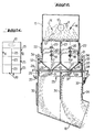
- Each box 25 comprises two Venturi 26 which are transversely juxtaposed in the box.
- Each V-shaped venturi 26 is of elongated longitudinal shape, its neck 27 being constituted by an elongated rectangular slot.
- the section of the neck 27 is adjustable, by means of a plate 28 which is slidably mounted between two guide plates 29 of the box and the internal end of which more or less closes the slot constituting the neck 27 of the Venturi.
- Each box 25 is mounted vertically mobile, in the enclosure 24, between an upper service position which is that shown in FIG. 2, and a lower position, not shown, in which the box 25 is brought opposite a door. 32 of the enclosure 24. In this lower position, the box 25 can be removed from the enclosure 24, to be cleaned or replaced.
- Each box 25 can be supported by a rigid frame connected to handling cables 33 passing over pulleys 34 and arriving at winches 35, or else each box 25 can itself be directly connected to cables 33.
- a central wall 36 similar to the aforementioned removable central wall 23, is hung under each box 36.
- the spoon-shaped part 31 placed at the output from the neck 27 of each Venturi 26, makes it possible to retransform by shock, the water mist resulting from the atomization, into large droplets.
- the mixture of liquid and air leaving the Venturi 26 is guided, by the parts 31, on the one hand on some of the internal walls of the enclosure 24, and on the other hand on one face of the central wall 36.
- spraying ramps for washing liquid at low pressure, shown at 37, are provided on the other walls of the enclosure 24, to prevent them from depositing and sticking of dust and binder.
- the washing liquid laden with dust and binder is treated, in a conventional manner, for the separation of dust and binders, and is then advantageously recycled in the spraying booms 17 and 37.
- each box 25 can comprise several Venturi transversely juxtaposed, their number not necessarily being two as in the example shown in FIG. 2.
Landscapes
- Engineering & Computer Science (AREA)
- Textile Engineering (AREA)
- Chemical & Material Sciences (AREA)
- Inorganic Chemistry (AREA)
- Chemical Kinetics & Catalysis (AREA)
- Dispersion Chemistry (AREA)
- General Chemical & Material Sciences (AREA)
- Nonwoven Fabrics (AREA)
- Paper (AREA)
- Treatment Of Fiber Materials (AREA)
Applications Claiming Priority (2)
| Application Number | Priority Date | Filing Date | Title |
|---|---|---|---|
| FR7917133A FR2460360A1 (fr) | 1979-07-02 | 1979-07-02 | Procede et dispositif de depollution dans une installation de fabrication d'un matelas de fibres |
| FR7917133 | 1979-07-02 |
Publications (2)
| Publication Number | Publication Date |
|---|---|
| EP0022035A1 EP0022035A1 (fr) | 1981-01-07 |
| EP0022035B1 true EP0022035B1 (fr) | 1983-12-07 |
Family
ID=9227390
Family Applications (1)
| Application Number | Title | Priority Date | Filing Date |
|---|---|---|---|
| EP80400998A Expired EP0022035B1 (fr) | 1979-07-02 | 1980-07-01 | Procédé et dispositif de dépollution dans une installation de fabrication d'un matelas de fibres |
Country Status (4)
| Country | Link |
|---|---|
| US (1) | US4298367A (cg-RX-API-DMAC10.html) |
| EP (1) | EP0022035B1 (cg-RX-API-DMAC10.html) |
| DE (1) | DE3065822D1 (cg-RX-API-DMAC10.html) |
| FR (1) | FR2460360A1 (cg-RX-API-DMAC10.html) |
Families Citing this family (5)
| Publication number | Priority date | Publication date | Assignee | Title |
|---|---|---|---|---|
| US4826514A (en) * | 1987-06-23 | 1989-05-02 | Griffis Steven C | Apparatus for dampening hazardous material |
| US4786296A (en) * | 1987-06-23 | 1988-11-22 | Griffis Steven C | Apparatus for use in asbestos removal |
| JP2578901B2 (ja) * | 1988-04-21 | 1997-02-05 | 株式会社大氣社 | 遠心分離型塗料ミスト含有気体浄化装置 |
| WO1991001184A1 (en) * | 1989-07-18 | 1991-02-07 | Bartimote John K | Material handling apparatus and method |
| KR100419415B1 (ko) * | 2001-10-22 | 2004-02-19 | 삼성전자주식회사 | 광섬유 제조장치의 드로우타워 차단도어 |
Family Cites Families (9)
| Publication number | Priority date | Publication date | Assignee | Title |
|---|---|---|---|---|
| US2337983A (en) * | 1941-05-13 | 1943-12-28 | Ernest F Fisher | Spray booth |
| US3795093A (en) * | 1972-04-27 | 1974-03-05 | Svenska Flaektfabriken Ab | Apparatus for cleaning the air from a spray painting chamber |
| US3881898A (en) * | 1973-01-18 | 1975-05-06 | Lodge Cottrell Ltd | Gas treatment |
| FR2318121A1 (fr) * | 1975-02-10 | 1977-02-11 | Saint Gobain | Perfectionnement a la fabrication de nappes ou matelas de fibres de matiere thermoplastique, telle que le verre |
| US4105424A (en) * | 1973-03-30 | 1978-08-08 | Saint-Gobain Industries | Method and apparatus for suppression of pollution in mineral fiber manufacture |
| FR2247346B1 (cg-RX-API-DMAC10.html) * | 1973-10-10 | 1978-02-17 | Saint Gobain | |
| FR2368445A1 (fr) * | 1976-10-22 | 1978-05-19 | Saint Gobain | Regulation des installations de fibrage avec traitement des effluents |
| ZA756778B (en) * | 1974-12-12 | 1977-06-29 | Owens Corning Fiberglass Corp | Pollution control system for removing particles in stack gases |
| US4239512A (en) * | 1977-07-21 | 1980-12-16 | Binks Manufacturing Company | Air washer particularly for paint spray booths |
-
1979
- 1979-07-02 FR FR7917133A patent/FR2460360A1/fr active Granted
-
1980
- 1980-07-01 US US06/165,031 patent/US4298367A/en not_active Expired - Lifetime
- 1980-07-01 DE DE8080400998T patent/DE3065822D1/de not_active Expired
- 1980-07-01 EP EP80400998A patent/EP0022035B1/fr not_active Expired
Also Published As
| Publication number | Publication date |
|---|---|
| EP0022035A1 (fr) | 1981-01-07 |
| US4298367A (en) | 1981-11-03 |
| FR2460360B1 (cg-RX-API-DMAC10.html) | 1983-08-19 |
| FR2460360A1 (fr) | 1981-01-23 |
| DE3065822D1 (en) | 1984-01-12 |
Similar Documents
| Publication | Publication Date | Title |
|---|---|---|
| US4812231A (en) | Self cleaning rotating fine polishing filter screen apparatus | |
| CA2259455C (fr) | Procede et dispositif de protection d'un plan de travail | |
| CN1177639C (zh) | 废水用清洁装置 | |
| DE4218699C2 (de) | Durchström-Trockner zur Trocknung von Schlämmen mit Filteranordnung | |
| KR101547487B1 (ko) | 하향 세척 먼지 제거 장치 | |
| US5549734A (en) | Baghouse cleaning method | |
| HUE026311T2 (en) | Painting cabinet equipped with cleaning equipment | |
| EP0022035B1 (fr) | Procédé et dispositif de dépollution dans une installation de fabrication d'un matelas de fibres | |
| EP3808461A1 (fr) | Machine automatique de tri ou d'inspection d'objets défilants, équipée d'un dispositif de nettoyage | |
| EP0072301B1 (fr) | Procédé et dispositif pour l'amélioration des conditions de formation des matelas de fibres | |
| US5590488A (en) | Sod handling | |
| US6578714B2 (en) | Mobile washer with fluid reclamation system | |
| JPS60192604A (ja) | 丸太洗浄装置 | |
| KR20230055139A (ko) | 꼬막 치패 분리장치 | |
| EP0016698B1 (fr) | Cabine de peinture, pour véhicule automobile par exemple | |
| EP0002402A1 (fr) | Aspirateur à double filtrage | |
| FR2466519A1 (fr) | Dispositif de nettoyage et de depoussierage de flocons de fibres textiles | |
| US4821754A (en) | Flitch washer | |
| CN218395126U (zh) | 一种飞机发动机点火嘴清洁装置 | |
| FR2653353A1 (fr) | Procede et installation d'epuration d'air. | |
| FR2700758A1 (fr) | Dispositif de nettoyage pour tapis transporteur d'un surgélateur de produits alimentaires en vrac et surgélateur équipé de ce dispositif. | |
| DE2703819A1 (de) | Verfahren und vorrichtung zum reinigen von teppichen | |
| EP0062586B1 (fr) | Procédé et dispositif de lavage utilisés dans la fabrication de matelas de fibres minérales | |
| EP2799372A1 (en) | A method and a processing station for processing shell eggs | |
| EP3000536A1 (fr) | Dispositif de nettoyage d'un crible |
Legal Events
| Date | Code | Title | Description |
|---|---|---|---|
| PUAI | Public reference made under article 153(3) epc to a published international application that has entered the european phase |
Free format text: ORIGINAL CODE: 0009012 |
|
| AK | Designated contracting states |
Designated state(s): BE DE NL |
|
| 17P | Request for examination filed |
Effective date: 19810331 |
|
| RAP1 | Party data changed (applicant data changed or rights of an application transferred) |
Owner name: FLAEKT AKTIEBOLAG |
|
| GRAA | (expected) grant |
Free format text: ORIGINAL CODE: 0009210 |
|
| AK | Designated contracting states |
Designated state(s): BE DE NL |
|
| REF | Corresponds to: |
Ref document number: 3065822 Country of ref document: DE Date of ref document: 19840112 |
|
| PLBE | No opposition filed within time limit |
Free format text: ORIGINAL CODE: 0009261 |
|
| STAA | Information on the status of an ep patent application or granted ep patent |
Free format text: STATUS: NO OPPOSITION FILED WITHIN TIME LIMIT |
|
| 26N | No opposition filed | ||
| PGFP | Annual fee paid to national office [announced via postgrant information from national office to epo] |
Ref country code: DE Payment date: 19950617 Year of fee payment: 16 |
|
| PGFP | Annual fee paid to national office [announced via postgrant information from national office to epo] |
Ref country code: NL Payment date: 19950727 Year of fee payment: 16 |
|
| PGFP | Annual fee paid to national office [announced via postgrant information from national office to epo] |
Ref country code: BE Payment date: 19950809 Year of fee payment: 16 |
|
| PG25 | Lapsed in a contracting state [announced via postgrant information from national office to epo] |
Ref country code: BE Effective date: 19960731 |
|
| BERE | Be: lapsed |
Owner name: FLAKT A.B. Effective date: 19960731 |
|
| PG25 | Lapsed in a contracting state [announced via postgrant information from national office to epo] |
Ref country code: NL Effective date: 19970201 |
|
| NLV4 | Nl: lapsed or anulled due to non-payment of the annual fee |
Effective date: 19970201 |
|
| PG25 | Lapsed in a contracting state [announced via postgrant information from national office to epo] |
Ref country code: DE Effective date: 19970402 |