EP0021849B1 - Reusable releasable fastener - Google Patents
Reusable releasable fastener Download PDFInfo
- Publication number
- EP0021849B1 EP0021849B1 EP80302217A EP80302217A EP0021849B1 EP 0021849 B1 EP0021849 B1 EP 0021849B1 EP 80302217 A EP80302217 A EP 80302217A EP 80302217 A EP80302217 A EP 80302217A EP 0021849 B1 EP0021849 B1 EP 0021849B1
- Authority
- EP
- European Patent Office
- Prior art keywords
- fastener
- shaft
- slot
- generally
- tool
- Prior art date
- Legal status (The legal status is an assumption and is not a legal conclusion. Google has not performed a legal analysis and makes no representation as to the accuracy of the status listed.)
- Expired
Links
- 230000000717 retained effect Effects 0.000 claims description 13
- 238000000926 separation method Methods 0.000 claims description 8
- 230000037431 insertion Effects 0.000 claims 1
- 238000003780 insertion Methods 0.000 claims 1
- 230000014759 maintenance of location Effects 0.000 description 3
- 229910000639 Spring steel Inorganic materials 0.000 description 2
- 239000002184 metal Substances 0.000 description 2
- 229910052751 metal Inorganic materials 0.000 description 2
- 230000006835 compression Effects 0.000 description 1
- 238000007906 compression Methods 0.000 description 1
- 230000008676 import Effects 0.000 description 1
- 238000004519 manufacturing process Methods 0.000 description 1
- 239000000463 material Substances 0.000 description 1
- 150000002739 metals Chemical class 0.000 description 1
- 239000002991 molded plastic Substances 0.000 description 1
- 239000012858 resilient material Substances 0.000 description 1
- 229910001220 stainless steel Inorganic materials 0.000 description 1
- 239000010935 stainless steel Substances 0.000 description 1
- 238000003466 welding Methods 0.000 description 1
Images
Classifications
-
- F—MECHANICAL ENGINEERING; LIGHTING; HEATING; WEAPONS; BLASTING
- F16—ENGINEERING ELEMENTS AND UNITS; GENERAL MEASURES FOR PRODUCING AND MAINTAINING EFFECTIVE FUNCTIONING OF MACHINES OR INSTALLATIONS; THERMAL INSULATION IN GENERAL
- F16B—DEVICES FOR FASTENING OR SECURING CONSTRUCTIONAL ELEMENTS OR MACHINE PARTS TOGETHER, e.g. NAILS, BOLTS, CIRCLIPS, CLAMPS, CLIPS OR WEDGES; JOINTS OR JOINTING
- F16B41/00—Measures against loss of bolts, nuts, or pins; Measures against unauthorised operation of bolts, nuts or pins
- F16B41/005—Measures against unauthorised operation of bolts, nuts or pins
-
- E—FIXED CONSTRUCTIONS
- E05—LOCKS; KEYS; WINDOW OR DOOR FITTINGS; SAFES
- E05B—LOCKS; ACCESSORIES THEREFOR; HANDCUFFS
- E05B73/00—Devices for locking portable objects against unauthorised removal; Miscellaneous locking devices
- E05B73/0017—Anti-theft devices, e.g. tags or monitors, fixed to articles, e.g. clothes, and to be removed at the check-out of shops
-
- F—MECHANICAL ENGINEERING; LIGHTING; HEATING; WEAPONS; BLASTING
- F16—ENGINEERING ELEMENTS AND UNITS; GENERAL MEASURES FOR PRODUCING AND MAINTAINING EFFECTIVE FUNCTIONING OF MACHINES OR INSTALLATIONS; THERMAL INSULATION IN GENERAL
- F16B—DEVICES FOR FASTENING OR SECURING CONSTRUCTIONAL ELEMENTS OR MACHINE PARTS TOGETHER, e.g. NAILS, BOLTS, CIRCLIPS, CLAMPS, CLIPS OR WEDGES; JOINTS OR JOINTING
- F16B21/00—Means for preventing relative axial movement of a pin, spigot, shaft or the like and a member surrounding it; Stud-and-socket releasable fastenings
- F16B21/10—Means for preventing relative axial movement of a pin, spigot, shaft or the like and a member surrounding it; Stud-and-socket releasable fastenings by separate parts
- F16B21/20—Means for preventing relative axial movement of a pin, spigot, shaft or the like and a member surrounding it; Stud-and-socket releasable fastenings by separate parts for bolts or shafts without holes, grooves, or notches for locking members
-
- Y—GENERAL TAGGING OF NEW TECHNOLOGICAL DEVELOPMENTS; GENERAL TAGGING OF CROSS-SECTIONAL TECHNOLOGIES SPANNING OVER SEVERAL SECTIONS OF THE IPC; TECHNICAL SUBJECTS COVERED BY FORMER USPC CROSS-REFERENCE ART COLLECTIONS [XRACs] AND DIGESTS
- Y10—TECHNICAL SUBJECTS COVERED BY FORMER USPC
- Y10T—TECHNICAL SUBJECTS COVERED BY FORMER US CLASSIFICATION
- Y10T24/00—Buckles, buttons, clasps, etc.
- Y10T24/44—Clasp, clip, support-clamp, or required component thereof
- Y10T24/44641—Clasp, clip, support-clamp, or required component thereof having gripping member formed from, biased by, or mounted on resilient member
- Y10T24/44769—Opposed engaging faces on gripping member formed from single piece of resilient material
- Y10T24/44923—Clasp, clip, or support-clamp cut or shaped from a single sheet of resilient, uniformly thick, planar material
-
- Y—GENERAL TAGGING OF NEW TECHNOLOGICAL DEVELOPMENTS; GENERAL TAGGING OF CROSS-SECTIONAL TECHNOLOGIES SPANNING OVER SEVERAL SECTIONS OF THE IPC; TECHNICAL SUBJECTS COVERED BY FORMER USPC CROSS-REFERENCE ART COLLECTIONS [XRACs] AND DIGESTS
- Y10—TECHNICAL SUBJECTS COVERED BY FORMER USPC
- Y10T—TECHNICAL SUBJECTS COVERED BY FORMER US CLASSIFICATION
- Y10T24/00—Buckles, buttons, clasps, etc.
- Y10T24/50—Readily interlocking, two-part fastener requiring either destructive or tool disengagement
-
- Y—GENERAL TAGGING OF NEW TECHNOLOGICAL DEVELOPMENTS; GENERAL TAGGING OF CROSS-SECTIONAL TECHNOLOGIES SPANNING OVER SEVERAL SECTIONS OF THE IPC; TECHNICAL SUBJECTS COVERED BY FORMER USPC CROSS-REFERENCE ART COLLECTIONS [XRACs] AND DIGESTS
- Y10—TECHNICAL SUBJECTS COVERED BY FORMER USPC
- Y10T—TECHNICAL SUBJECTS COVERED BY FORMER US CLASSIFICATION
- Y10T70/00—Locks
- Y10T70/50—Special application
- Y10T70/5004—For antitheft signaling device on protected article
Definitions
- This invention relates to reusable, releasable, tamper resistant fasteners which are removably attachable to shafts, such as shafts of pin members, and which are designed to be nondestructably releasable from the pin member only upon the use of a special tool.
- a reusable releasable, tamper resistant fastener is particularly suitable for use in connection with a monitor actuating device for removable attachment to the shank of a pin member to attach a monitored article to the monitor actuating device and for nondestructive removal from the pin shank upon the use of a special tool.
- Reusable releasable fasteners for selective attachment to the free end of the shanks of pin members or the like for use in connection with monitor actuating devices, such as are commonly used in anti-theft systems to capture a monitored article on the shank of the pin member between the head of the pin and the removable fastener and for resisting nondestructive removal from the pin shank except upon the use of a special tool are well known in the prior art and examples thereof may be seen by reference to United States Patents Nos. 3,911,534; 3,914,829; 3,932,918; 4,000,543 and 4,104,622. The latter two of these documents both disclose a fastener conforming to the pre-characterising part of appended claim 1.
- the object of the invention is to provide an improved reusable, releasable tamper-resistant fastener which is relatively inexpensively produced, operates on a different principle and utilises a different type of release tool than prior art devices.
- the fastener comprises a generally hollow body comprising a bottom portion and generally dome-shaped portion defining a cavity therebetween, the bottom portion having a generally centrally located aperture therethrough of greater cross-sectional dimension than the cross-section of the shaft, the dome-shaped portion having an elongated slot therein opening to the cavity, the slot having a central portion aligned with the aperture; and a one-piece spring clip substantially nonrotationally retained in the cavity of the body, the clip having a generally U-shaped cross-section taken on a plane generally perpendicular to the longitudinal axis of the slot and comprising a base portion and two leg portions extending upwardly and inwardly from opposite ends of the base portion, a pair of oppositely extending cantilevered spring fingers cut from the base portion or the leg portions, the free ends of the spring fingers defining a pair of spaced apart opposed edges separated by
- the spring fingers are cut from the base portion.
- individualised systems of removable fasteners may be provided utilising common components of fastener bottom portions and clip members.
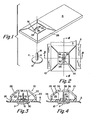
- a monitor actuating device D incorporating a reusable releasable fastener 10 in accordance with the present invention for selective, releasable retention of a pin member P may be seen by reference to Figure 1.
- the headed pin P which might be a tack, is utilised to pierce a monitored article A and, in combination with fastener 10, will releasably retain the article to the monitor actuating device D.
- the headed pin P comprises a headed portion 12 and an axially extending shaft 14 of sufficient length to pierce the monitored article and to be retained in fastener 10.
- the free end 16 of the shank 14 is conveniently pointed to facilitate piercing of monitored objects.
- the exterior surface of the monitor actuating device D is conveniently of a tough and resilient material to prevent vandalism and the device D includes a sensor actuating member or means encapsulated therein.
- the sensor actuating member may be a magnet, a radio transmitter; a radio antenna or similar device as is well known in the art. It is understood that the actual form of the monitor actuating member forms no part of the present invention.
- the monitor actuating device D is intended for use in anti-shoplifting systems which are described in some detail in United States Patent Nos. 3,665,448; 3,631,442; 3,557,136.
- fastener 10 in combination with pin P to retain a monitored article A to the monitor actuating device D may be seen in greater detail by reference to Figures 2, 3 and 4. Briefly, the monitored article A is pierced by the pointed end 16 of the pin shank 14 which is then pushed into the fastener 10 and retained therein to trap the monitored article A between fastener 10 and the head 12 of pin P.
- the fastener 10 comprises a generally hollow body 20 which is conveniently formed integrally with the monitor actuating device D and a one-piece spring clip 22 retained within the body 20 for releasably engaging the shank 14 of pin P.
- Clip 22 may be of spring steel, stainless steel or other suitable tempered metals.
- the body may be of a moulded plastics material and comprises a lower or bottom portion 24 and an upper or dome-shaped portion 26 defining a cavity 28 therebetween in which clip 22 is substantially nonrotationally received.
- the upper and lower portions of body 20 are joined by ultrasonic welding for example.
- the lower portion 24 of body 20 includes an aperture 30 therethrough for receipt of the shank 14 of pin P and the dome-shaped portion 26 of the body 20 includes an elongated slot 32.
- the slot 32 comprises two elongated portions 34 and 36 of greater length than width joined by a central portion 38 of a generally annular shape having a diameter greater than the width of slot portions 34 and 36.
- the central portion 38 of the slot 32 in the dome-shaped portions is axially aligned with the aperture 30 in the lower portion of the body.
- the clip 22 is a one-piece resiliently deformable sheet metal stamping which may be seen in greater detail by reference to Figures 5 and 9.
- the clip is generally U-shaped in a cross section taken perpendicular to the longitudinal axis of slot 32.
- the clip 22 comprises a base portion 40 and two leg portions 42 and 44 which extend upwardly and inwardly from the base portion of the nondeformed position of the clip.
- a pair of oppositely extending generally arcuately shaped cantilevered spring fingers 46 and 48 are cut out from the base portion and define a pair of opposed edges 50 and 52 separated by a distance which is less than the diameter of the shaft 14 of the pin to be removably retained by the fastener 10 in the nondeformed position of clip 22.
- the opposed edges 50 and 52 include aligned generally concave notches 54 and 56 for receipt and retention of pin shaft 14.
- the generally annular space 57 between the notches 54 and 56 in the opposed edges 50 and 52 is aligned with aperture 30 and the central portion 38 of slot 32 when the clip is retained within the fastener body.
- the base portion 40 of clip 22 is of a length 58 which will engage the side wall of the dome-shaped portion 26 of the fastener body to prevent, or limit, rotation of clip 22 relative to the fastener body 20.
- Optional notches 59 are also provided in the base portion 40 to engage a structure (not shown) of the body to prevent or limit rotation of clip 22 relative to body 20.
- the bottom portion 24 of fastener body 20 preferably includes a generally convex protrusion 60 surrounding aperture 30 for engagement of the undersides of spring fingers 46 and 48 to prevent downward deflection thereof towards the exterior opening of aperture 30 to prevent or resist removal of a retained pin P from fastener 10 by simply forcing pin P downwardly and outwardly from fastener 10.
- resilient deflection of leg portions 42 and 44 outwardly will result in the spacing between edges 50 and 52 increasing to a distance 62 which is generally equal to or greater than the diameter of the shaft 14 of pin P allowing the pin to be easily removed from fastener 10 when the clip 22 is deformed to the position represented by the dotted line figure.
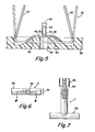
- the specially configured tool T for use in connection with fastener 10 for selective release of fastener 10 from a received pin P may be seen by reference to Figures 6, 7, and 8.
- the tool T comprises a handle portion 62, shaft or shank portion 64 extending from the handle and a head portion 66 attached to the end of shank 64 remote from handle 62.
- the head portion 66 is in the form of a generally flat plate having a length 70, a height 72 and a width 74.
- the length 70 is slightly less than the length of slot 32 and the width 74 is slight less than the width of slot 32 allowing the head portion 66 to be passed through the slot 32 and into the cavity 28 of fastener body 20.
- the length 70 of the threaded portion 66 is greater than the separation between the leg portions 44 and 42 of the clip 22 in the nondeformed position thereof. When leg portions 42 and 44 are separated by a distance generally equal to length 70, the fastener will assume the position shown in dotted lines in Figure 5 allowing a retained pin to be easily removed therefrom.
- the height 72 of head portion 66 is preferably slightly less than the separation of the upper and lower portions of the body 20 of fastener 10.
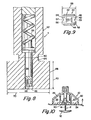
- the outer diameter 80 of shank portion 64 of tool T is configured to allow rotation of tool T when the head 66 is fully inserted into the slot.
- the head 66 of tool T may include a centrally located bore 82 in which a spring loaded piston 84 is received.
- Piston 84 is biased downwardly towards the end of the bore and is resiliently movable upwardly by compression of spring 86.
- Spring loaded piston 84 has an end 88 designed to engage the free end 18 of pin shaft 16 and will be effective to force pin P outwardly from fastener 10 when the pin shaft 16 is disengaged by the spring fingers 46 and 48.
- the object A to be monitored is pierced by pin P and then the free end 16 of pin shaft 14 is forced through bore 30 into the fastener 10 whereat the spring fingers 48 and 46 will deflect upwardly to grippingly engage the shaft to entrap the monitored article A between the head 12 of the pin and the fastener body 20.
- the protrusion 60 will engage the undersides of spring fingers 46 and 48 to resist collapsing thereof upon attempts to axially remove the pin P from fastener 10 without the use of the specially configured tool T.
- the specially configured tool T is utilized.
- the head portion 66 of the tool T is aligned with slot 32 and the head portion is then inserted fully through the slot and into the cavity 28. In this position, the longer edges of the tool head portion 66 will be substantially parallel with leg portions 44 and 42 of clip 22.
- the free end 16 of pin P will have engaged spring biased piston 84 causing same to move upwardly against the bias of spring 86.
- the tool T is then rotated approximately 90° (to the position of Figure 10) causing the edges thereof to engage the leg portions 42 and 44 of spring clip 22 and to resiliently deform same outwardly which will result in a separation of the opposed edges 50 and 52 of spring fingers 46 and 48 sufficient to cause the spring fingers to disengage the shaft 14 of pin P.
- the pin may then be simply axially removed or will be ejected automatically under the force of the spring biased piston 84.
- the tool T is then rotated 90° to align same with slot 32 and then simply removed from fastener 10 allowing the fastener 10 to be reused as desired.
Landscapes
- Engineering & Computer Science (AREA)
- General Engineering & Computer Science (AREA)
- Mechanical Engineering (AREA)
- Slide Fasteners, Snap Fasteners, And Hook Fasteners (AREA)
- Burglar Alarm Systems (AREA)
Applications Claiming Priority (2)
| Application Number | Priority Date | Filing Date | Title |
|---|---|---|---|
| US53889 | 1979-07-02 | ||
| US06/053,889 US4311992A (en) | 1979-07-02 | 1979-07-02 | Reusable releasable fastener |
Publications (2)
| Publication Number | Publication Date |
|---|---|
| EP0021849A1 EP0021849A1 (en) | 1981-01-07 |
| EP0021849B1 true EP0021849B1 (en) | 1983-05-11 |
Family
ID=21987241
Family Applications (1)
| Application Number | Title | Priority Date | Filing Date |
|---|---|---|---|
| EP80302217A Expired EP0021849B1 (en) | 1979-07-02 | 1980-07-01 | Reusable releasable fastener |
Country Status (5)
| Country | Link |
|---|---|
| US (1) | US4311992A (OSRAM) |
| EP (1) | EP0021849B1 (OSRAM) |
| JP (1) | JPS5616172A (OSRAM) |
| AU (1) | AU6000280A (OSRAM) |
| DE (1) | DE3063111D1 (OSRAM) |
Cited By (1)
| Publication number | Priority date | Publication date | Assignee | Title |
|---|---|---|---|---|
| DE102005062414A1 (de) * | 2005-12-23 | 2007-06-28 | Werner Seeger | Etikett für die Warensicherung |
Families Citing this family (37)
| Publication number | Priority date | Publication date | Assignee | Title |
|---|---|---|---|---|
| US4395800A (en) * | 1980-10-20 | 1983-08-02 | Deere & Company | Hose retainer |
| DE3143208C2 (de) * | 1981-10-30 | 1984-07-05 | Max-E. Dipl.-Ing. 7320 Göppingen Reeb | Identifizierungsanordnung in Form eines an einem Gegenstand anbringbaren etikettartigen Streifens und Verfahren zu deren Herstellung |
| US4722119A (en) * | 1985-04-08 | 1988-02-02 | Green Perry A | Anti-theft fastening device |
| US4774504A (en) * | 1987-06-22 | 1988-09-27 | Monarch Marking Systems, Inc. | EAS tag with helical coil |
| US4774503A (en) * | 1987-06-22 | 1988-09-27 | Monarch Marking Systems, Inc. | Anti-theft tag |
| FR2643687B1 (fr) * | 1989-02-24 | 1991-08-02 | Py Marc | Procede et dispositif pour fixer une cloison transversale dans un tube |
| US4993245A (en) * | 1989-03-28 | 1991-02-19 | Frank Ott | Security tag for use on articles of clothing and the like |
| US5031287A (en) * | 1989-06-01 | 1991-07-16 | Security Tag Systems, Inc. | Detrimental-substance-containing theft-deterrent device |
| DE3938059A1 (de) * | 1989-11-16 | 1991-06-13 | Telefunken Electronic Gmbh | Vorrichtung zum befestigen eines sicherungsetikettes |
| US4987754A (en) * | 1990-01-12 | 1991-01-29 | Knogo Corporation | Magnetically releasable target lock |
| CH684134A5 (de) * | 1991-12-16 | 1994-07-15 | Heinrich Sieber | An einen Gegenstand anbringbarer Sicherungsanhänger zur Signalisierung eines versuchten Diebstahls. |
| US5426419A (en) * | 1993-01-14 | 1995-06-20 | Sensormatic Electronics Corporation | Security tag having arcuate channel and detacher apparatus for same |
| US5524463A (en) * | 1994-01-11 | 1996-06-11 | Sensormatic Electronics Corporation | Theft deterrent device to facilitate easy protection of large irregularly-shaped goods |
| SE9401218L (sv) * | 1994-04-12 | 1995-10-13 | Mw Trading Aps | Larmbricka |
| US5528914A (en) * | 1994-09-27 | 1996-06-25 | Sensormatic Electronics Corporation | Security tag and complemental deactivation apparatus |
| US5535606A (en) * | 1994-09-27 | 1996-07-16 | Sensormatic Electronics Corporation | Compact power detacher |
| FR2796426A1 (fr) * | 1999-07-13 | 2001-01-19 | Gobin Daude | Dispositif de fixation demontable a base de rondelle elastique |
| JP4252713B2 (ja) * | 2000-08-31 | 2009-04-08 | センサーマチック・エレクトロニックス・コーポレーション | 盗難防止装置 |
| AU2002225925A1 (en) | 2000-10-26 | 2002-05-06 | Alpha Security Products, Inc. | Eas tag holder |
| DE10126288A1 (de) * | 2001-05-29 | 2003-01-02 | High Scan Artikelsicherungs Gm | Warensicherungsvorrichtung |
| USD468223S1 (en) | 2001-09-26 | 2003-01-07 | Alpha Security Products, Inc. | Anti-shoplifting EAS tag holder |
| USD466427S1 (en) | 2002-02-07 | 2002-12-03 | Alpha Security Products, Inc. | EAS tag holder |
| USD466037S1 (en) | 2002-02-07 | 2002-11-26 | Alpha Security Products, Inc. | EAS tag holder |
| WO2003088173A1 (en) * | 2002-04-08 | 2003-10-23 | Adel Odeh Sayegh | Article surveillance tag having a metal clip |
| US7652574B2 (en) * | 2002-04-08 | 2010-01-26 | Sayegh Adel O | Article surveillance tag having a vial |
| USD474417S1 (en) | 2002-05-31 | 2003-05-13 | Alpha Security Products, Inc. | Theft deterrent tag |
| USD478833S1 (en) | 2002-05-31 | 2003-08-26 | Alpha Security Products, Inc. | Theft deterrent tag |
| US7190272B2 (en) * | 2003-05-06 | 2007-03-13 | Xiao Hui Yang | EAS tag with ball clutch |
| USD494487S1 (en) * | 2003-06-02 | 2004-08-17 | Adel O. Sayegh | Electronic article surveillance device with attachment |
| USD497320S1 (en) * | 2003-06-02 | 2004-10-19 | Adel O. Sayegh | Compact electronic article surveillance device |
| US7400254B2 (en) | 2003-09-25 | 2008-07-15 | Xiao Hui Yang | EAS tag detachable by multiple methods |
| DE102004041602A1 (de) * | 2004-08-26 | 2006-11-16 | Sentronik Gmbh | Warensicherungseinrichtung mit Farbsicherung |
| US20060070411A1 (en) * | 2004-10-04 | 2006-04-06 | Sensormatic Electronics Corporation | Magnetic spring clamp |
| US20080084313A1 (en) * | 2006-10-10 | 2008-04-10 | Seidel Stuart T | Recyclable Anti-Theft Tag |
| US8117874B2 (en) * | 2008-08-07 | 2012-02-21 | Checkpoint Systems, Inc. | Theft deterrent device including a spring washer |
| CN102459791A (zh) * | 2009-04-10 | 2012-05-16 | 关卡系统公司 | 推销式安全装置 |
| CN111630237B (zh) * | 2018-01-18 | 2021-10-15 | 泽利德技术有限责任公司 | 服装物品的安全标签 |
Family Cites Families (14)
| Publication number | Priority date | Publication date | Assignee | Title |
|---|---|---|---|---|
| US3470637A (en) * | 1967-01-27 | 1969-10-07 | Scovill Manufacturing Co | Non-removable tag |
| US3631442A (en) * | 1968-03-22 | 1971-12-28 | Robert E Fearon | Anti-shoplifting system |
| US3665448A (en) * | 1970-08-03 | 1972-05-23 | Hugh A Mcglinchey | Electronic shoplifting prevention system |
| US3858280A (en) * | 1972-11-17 | 1975-01-07 | I D Engineering Inc | Fastening clip |
| US3914829A (en) * | 1973-06-01 | 1975-10-28 | Eaton Corp | Releasably attachable clip |
| US3932918A (en) * | 1973-06-01 | 1976-01-20 | Eaton Corporation | Releasably attachable clip |
| US3942829A (en) * | 1973-12-27 | 1976-03-09 | Sensormatic Electronics Corporation | Reusable security tag |
| US3911534A (en) * | 1974-10-30 | 1975-10-14 | I D Engineering Inc | Anti-theft fastening device |
| US3973418A (en) * | 1975-03-31 | 1976-08-10 | Mrs. Lawrence Israel | Reusable device for attaching an anti-theft monitor to merchandise |
| US4000543A (en) * | 1975-12-02 | 1977-01-04 | Eaton Corporation | Monitor actuating device and reusable fastener therefor |
| US4104622A (en) * | 1975-12-02 | 1978-08-01 | Eaton Corporation | Monitor actuating device and reusable fastener therefor |
| DE2656511C2 (de) * | 1976-12-14 | 1985-08-29 | Naamloze Vennootschap Nederlandsche Apparatenfabriek Nedap, Groenlo | Befestigungsvorrichtung |
| US4187509A (en) * | 1977-06-20 | 1980-02-05 | Knogo Corporation | Wafer and fastener for use in electronic theft detection system |
| US4156302A (en) * | 1978-03-09 | 1979-05-29 | Eaton Corporation | Monitor actuating assembly and reusable fastener device therefor |
-
1979
- 1979-07-02 US US06/053,889 patent/US4311992A/en not_active Expired - Lifetime
-
1980
- 1980-07-01 AU AU60002/80A patent/AU6000280A/en not_active Abandoned
- 1980-07-01 DE DE8080302217T patent/DE3063111D1/de not_active Expired
- 1980-07-01 EP EP80302217A patent/EP0021849B1/en not_active Expired
- 1980-07-02 JP JP8930380A patent/JPS5616172A/ja active Granted
Cited By (1)
| Publication number | Priority date | Publication date | Assignee | Title |
|---|---|---|---|---|
| DE102005062414A1 (de) * | 2005-12-23 | 2007-06-28 | Werner Seeger | Etikett für die Warensicherung |
Also Published As
| Publication number | Publication date |
|---|---|
| AU6000280A (en) | 1981-01-15 |
| JPS6343755B2 (OSRAM) | 1988-09-01 |
| DE3063111D1 (en) | 1983-06-16 |
| EP0021849A1 (en) | 1981-01-07 |
| JPS5616172A (en) | 1981-02-16 |
| US4311992A (en) | 1982-01-19 |
Similar Documents
| Publication | Publication Date | Title |
|---|---|---|
| EP0021849B1 (en) | Reusable releasable fastener | |
| US4590461A (en) | Tamper resistant target wafer and fastener assembly | |
| US5163795A (en) | Front mounted rivet with interlocked drive pin | |
| US4104622A (en) | Monitor actuating device and reusable fastener therefor | |
| US4531264A (en) | Theft detection system target fastener | |
| EP0004068B1 (en) | Reusable fastener device for a monitor actuating assembly | |
| US4000543A (en) | Monitor actuating device and reusable fastener therefor | |
| US5632581A (en) | Clip | |
| US7148805B2 (en) | Hard security tag and detaching device | |
| US4502717A (en) | Pneumatically releasable, tamper-resistant security tag | |
| WO1992012650A1 (en) | Fastening system | |
| US4438552A (en) | Plastic fastener | |
| US4547937A (en) | Snap lock connector with push-button release | |
| US2568584A (en) | Fastening device | |
| US20120255145A1 (en) | Closures with magnetic and mechanical snap fastening and method of making the same | |
| US5704746A (en) | Plastic fastener for threaded blind aperture | |
| EP0142748B1 (en) | A lock for securing a mark especially onto a textile article | |
| JPS61278610A (ja) | 釘を一体に有するプラスチツククリツプ | |
| JPH04211897A (ja) | 磁気解除可能なターゲット係止装置 | |
| JP2003534586A (ja) | 1つの部分から成る盗難抑止装置 | |
| JPH09317728A (ja) | 物品固定具と固定具の取り外し方法 | |
| US6749384B1 (en) | Drive rivet | |
| US4960354A (en) | Headed fastener retainer clip | |
| EP0537967B1 (en) | A headed stud | |
| US6491328B1 (en) | Bin seal and fastener |
Legal Events
| Date | Code | Title | Description |
|---|---|---|---|
| PUAI | Public reference made under article 153(3) epc to a published international application that has entered the european phase |
Free format text: ORIGINAL CODE: 0009012 |
|
| AK | Designated contracting states |
Designated state(s): DE FR GB |
|
| 17P | Request for examination filed |
Effective date: 19810514 |
|
| GRAA | (expected) grant |
Free format text: ORIGINAL CODE: 0009210 |
|
| AK | Designated contracting states |
Designated state(s): DE FR GB |
|
| REF | Corresponds to: |
Ref document number: 3063111 Country of ref document: DE Date of ref document: 19830616 |
|
| ET | Fr: translation filed | ||
| PLBE | No opposition filed within time limit |
Free format text: ORIGINAL CODE: 0009261 |
|
| STAA | Information on the status of an ep patent application or granted ep patent |
Free format text: STATUS: NO OPPOSITION FILED WITHIN TIME LIMIT |
|
| 26N | No opposition filed | ||
| PGFP | Annual fee paid to national office [announced via postgrant information from national office to epo] |
Ref country code: DE Payment date: 19840627 Year of fee payment: 5 |
|
| PGFP | Annual fee paid to national office [announced via postgrant information from national office to epo] |
Ref country code: FR Payment date: 19840629 Year of fee payment: 5 |
|
| PG25 | Lapsed in a contracting state [announced via postgrant information from national office to epo] |
Ref country code: FR Free format text: LAPSE BECAUSE OF NON-PAYMENT OF DUE FEES Effective date: 19880331 |
|
| PG25 | Lapsed in a contracting state [announced via postgrant information from national office to epo] |
Ref country code: DE Effective date: 19880401 |
|
| GBPC | Gb: european patent ceased through non-payment of renewal fee | ||
| REG | Reference to a national code |
Ref country code: FR Ref legal event code: ST |
|
| PG25 | Lapsed in a contracting state [announced via postgrant information from national office to epo] |
Ref country code: GB Free format text: LAPSE BECAUSE OF NON-PAYMENT OF DUE FEES Effective date: 19881118 |