EP0020252A1 - Dosing dispenser for a liquid product, and apparatus, such as a washing machine, provided with such a dispenser - Google Patents
Dosing dispenser for a liquid product, and apparatus, such as a washing machine, provided with such a dispenser Download PDFInfo
- Publication number
- EP0020252A1 EP0020252A1 EP80400723A EP80400723A EP0020252A1 EP 0020252 A1 EP0020252 A1 EP 0020252A1 EP 80400723 A EP80400723 A EP 80400723A EP 80400723 A EP80400723 A EP 80400723A EP 0020252 A1 EP0020252 A1 EP 0020252A1
- Authority
- EP
- European Patent Office
- Prior art keywords
- tank
- product
- pipe
- dosing
- reservoir
- Prior art date
- Legal status (The legal status is an assumption and is not a legal conclusion. Google has not performed a legal analysis and makes no representation as to the accuracy of the status listed.)
- Ceased
Links
Images

Classifications
-
- G—PHYSICS
- G01—MEASURING; TESTING
- G01F—MEASURING VOLUME, VOLUME FLOW, MASS FLOW OR LIQUID LEVEL; METERING BY VOLUME
- G01F11/00—Apparatus requiring external operation adapted at each repeated and identical operation to measure and separate a predetermined volume of fluid or fluent solid material from a supply or container, without regard to weight, and to deliver it
- G01F11/28—Apparatus requiring external operation adapted at each repeated and identical operation to measure and separate a predetermined volume of fluid or fluent solid material from a supply or container, without regard to weight, and to deliver it with stationary measuring chambers having constant volume during measurement
-
- D—TEXTILES; PAPER
- D06—TREATMENT OF TEXTILES OR THE LIKE; LAUNDERING; FLEXIBLE MATERIALS NOT OTHERWISE PROVIDED FOR
- D06F—LAUNDERING, DRYING, IRONING, PRESSING OR FOLDING TEXTILE ARTICLES
- D06F39/00—Details of washing machines not specific to a single type of machines covered by groups D06F9/00 - D06F27/00
- D06F39/02—Devices for adding soap or other washing agents
- D06F39/022—Devices for adding soap or other washing agents in a liquid state
Definitions
- the present invention relates to an assembly dispensing doses of liquid product and an apparatus provided with such an assembly.
- An appliance such as a washing machine or dishwashing machine usually comprises a container ensuring momentary maintenance and injection, at a predetermined instant of its operation, of a dose of treatment product into its tank.
- This treatment product can be a washing, rinsing, bleaching or softening product, etc.
- a large number of known devices do not have a reserve of treatment products in their enclosure, and receive each time they are put into use. walk, a dose of product deposited manually, in their product container. To this drawback is added the fact that this product container is never rinsed with water and the resulting fouling may inadvertently prevent this container from properly fulfilling its function.
- the present invention having the aim of avoiding these drawbacks, makes it possible to produce an assembly, made up in particular of static members, ensuring both the storage, the metering and the distribution of a liquid product, and the rinsing with water which prevents untimely fouling; and an apparatus provided with such an assembly which automatically distributes doses of product according to the device operation.
- an assembly distributing doses of liquid product having a reservoir for storage and means for dosing this product is characterized in that it comprises, at least, a reservoir for product hermetically closed by a cap. , a closed tank ensuring the metering of the product, mounted at a level lower than that of the tank and placed in communication by pipes, respectively with the highest part and with the lowest part of this tank, and a distribution system of the product and rinsing, consisting of three elements, namely a water supply line controlled by a solenoid valve and opening into the upper part of the tank, a bent pipe having one end opening into this tank, and a second end extending to a point below the level of this tank and serving as an evacuation siphon, and a bent pipe opening into the upper part of this tank and serving as a means of venting, and as an evacuation route product evaluation.
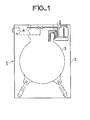
- An apparatus 1 produced according to the invention and presented under the form of a washing machine illustrated in Figure 1, includes a body 2, a tank 3 for receiving items to be washed, a programmer 4 controlling the operations to be performed by the device, provided in predetermined programs of operation, and an assembly 5 which provides storage, metering, automatic distribution of product doses, and rinsing with water preventing any untimely fouling.
- the assembly 5 is mounted in the part of the apparatus which is situated above the maximum level that the washing liquid in the tank 3 can usually reach.
- the assembly 5 illustrated in FIGS. 1 and 2 comprises a reservoir 6 for storing a liquid treatment product 7, a tank 8 for dosing this product, a system 9 for distributing the doses of this liquid product in the tank 3 and rinse.
- the reservoir 6 is constituted by a container having a volume exceeding several times that of the dose of product to be injected, and a shape affecting any desired geometric shape.
- This reservoir 6 is kept hermetically closed by a plug 10, and placed in communication not only with the lowest part of the dosing tank 8 which is located at a lower level, by means of a small diameter pipe 11, but also with the highest part of this tank 8, by means of a pipe 12.
- the dosing tank 8 consists of a closed container, the volume of which practically constitutes a planned dose of the liquid product to be dispensed.
- This dosing tank 8, apart from its connection with the reservoir 6, is in communication with the distribution and rinsing system 9 which comprises three elements, namely a water supply pipe 13 controlled by a solenoid valve 14, a pipe bent 15 serving as an evacuation siphon, and a bent pipe 16 serving as a venting and evacuation means.
- the pipe 13 and the pipe 16 are in communication with the upper part of the dosing tank 8 while the pipe 15 comprises an end 17 opening into this tank 8. In the example illustrated in FIG. 2, the end 17 of the pipe 15 is disposed near the bottom of the tank 8.
- the bent pipe 15 and the bent pipe 16 have the summits of their elbows situated above the maximum level of liquid product 7 located in the tank 6.
- the solenoid valve 14 which controls the flow of water in the line 13 is actuated by the programmer 4 of the device.
- the programmer 4 opens the solenoid valve 14, and the water coming from a distribution source not shown, enters via the line 13, in the dosing tank 8, and expels the liquid product therein.
- the product and the water are evacuated through the bent pipe 15 and the bent pipe 16.
- the water which enters the tank 8 creates the same pressure value at the top and at the bottom of the tank 6, through respectively the pipe 12 and the pipe 11. In this pressure condition, the mass of liquid product 7 remains in equilibrium in the tank 6 and the water does not enter this tank 6.
- the product in the dosing tank 8 is completely replaced by the water coming from line 13, the arrival of water continues and the passage of this water has the effect of cleaning both this tank 8 and the pipes 15 and pipe 16.
- the end of the operation for injecting the dose of treatment product into the tank 3 is also controlled by the programmer 4 which closes the solenoid valve 14 and thus cuts off the water supply to the dosing tank 8.
- the residual water in the tank 8 is evacuated by the siphoning effect by means of the bent pipe 15.
- the diameter of the pipe 11 which connects the tank 6 to the tank 8, is provided for much smaller than that of the bent pipe 15 so that the water is evacuated through this pipe 15, before the arrival in this tank 8 through the pipe 11, of a significant amount of liquid treatment product.
- the liquid product 7 by gravity descends from the reservoir 6, through the pipe 11 in the tank 8, to fill the latter and thus automatically carry out the dosing of the product.
- This downward movement of the liquid product 7 in the tank 8 stops automatically according to the principle of communicating vessels, as soon as the level of liquid product which overflows the tank 8 and rises in the pipe 15 and the pipe 16, s' aligns with the level of product remaining in the tank 6.
- the columns of liquid treatment product in the pipe 15 and pipe 16 represent, depending on the construction provided, a relatively small amount compared to the volume of the tank 8 and remaining below the tolerances allowed in the usual determination of the dose of such treatment product.
- the assembly 5 which provides storage, metering, automatic distribution of doses of liquid treatment product and rinsing with water comprises the same organs or elements as those of the assembly 5 illustrated in FIG. 2 with the exception of the bent pipe 15 serving as a siphon for discharging liquid.
- the fixed and bent pipe 15 of the assembly 5 of FIG. 2 is replaced by a bent pipe 18, one of the ends of which is mounted adjustable in height in the tank 8.
- the bent pipe 18 is, for example guided at the level of the tank 8 by a sheath 19 which makes its end vertically sliding and sealed, and at its second branch by a guide piece 20.
- the sliding mounting of the pipe 18 makes it possible to approach or move away its end of the bottom of the dosing tank 8.
- the solenoid valve 14 is closed, the entire quantity of water contained in the tank 8 is evacuated by siphoning by this pipe 18, before the product arrives liquid 7, via line 11.
- the entire volume of tank 8 is available to accommodate the arrival of this liquid product 7 coming from the reservoir 6.
- the dose of product 7 is in this case maximum.
- the end of the line 18 is for example at half of the height of the tank 8, half of the water contained in this tank 8 can only be emptied by siphoning by this pipe 18.
- the siphoning is defused and the evacuation of water from the tank is stopped.
- only half of the volume of the tank 8 is available to accommodate the liquid product 7 coming down from the reservoir 6.
- the dose of product is then reduced by half compared to the maximum dose indicated in a previous paragraph.
- the assembly 5 which provides storage, metering, automatic distribution of doses of liquid treatment product and rinsing with water comprises the same organs or elements as those of the assembly illustrated in Figure 2 with the exception of tray 8 which is replaced by a tray 22 adjustable in volume.
- This tank 22 is constituted by a container with a side wall in the form of a bellows schematically represented in FIG. 4, or in a telescopic form not shown.
- the volume of the tray 22 is adjusted for example by a device 23 such as a screw and nut system diagrammatically shown, or any other known system which makes it possible to bring the two opposite walls of the tray 22 closer or further apart to decrease or increase the volume respectively.
- the bent pipe 15 can slide, for example in guide devices 24 and 25.
Abstract
Description
La présente invention concerne un ensemble distribuant des doses de produit liquide et un appareil muni d'un tel ensemble.The present invention relates to an assembly dispensing doses of liquid product and an apparatus provided with such an assembly.
Un appareil tel qu'une machine à laver le linge ou la vaisselle comprend habituellement un récipient assurant un maintien momentané et une injection, à un instant prédéterminé de son fonctionnement, d'une dose de produit de traitement dans sa cuve. Ce produit de traitement peut être un produit de lavage, rinçage, blanchiment ou assouplissant etc... Cependant un grand nombre d'appareils connus ne possèdent pas dans leur enceinte une réserve de produits de traitement, et reçoivent préalablement à chacune de leur mise en marche, une dose de produit déposée manuellement, dans leur récipient à produit. A cet inconvénient s'ajoute le fait que ce récipient à produit n'est jamais rincé à l'eau et l'encrassement qui en résulte peut empêcher inopportunément ce récipient de remplir correctement sa fonction.An appliance such as a washing machine or dishwashing machine usually comprises a container ensuring momentary maintenance and injection, at a predetermined instant of its operation, of a dose of treatment product into its tank. This treatment product can be a washing, rinsing, bleaching or softening product, etc. However, a large number of known devices do not have a reserve of treatment products in their enclosure, and receive each time they are put into use. walk, a dose of product deposited manually, in their product container. To this drawback is added the fact that this product container is never rinsed with water and the resulting fouling may inadvertently prevent this container from properly fulfilling its function.
Toutefois, dans certains appareils connus existe une réserve de produit de traitement, mais celle-ci est par structure, constamment mise à l'air en vue de faciliter le soutirage du produit qu'elle contient. Cette mise à l'air continue provoque désavantageusement une oxydation rapide du produit en réserve. En outre, dans ces appareils connus, le soutirage du produit de la réserve exige souvent la présence d'un appareillage relativement compliqué et comportant des pièces mécaniques en mouvement. La fiabilité de cet appareillage dépend notamment du bon fonctionnement de ces pièces mécaniques.However, in certain known devices there is a reserve of treatment product, but this is by structure, constantly vented in order to facilitate the withdrawal of the product which it contains. This continuous venting disadvantageously causes rapid oxidation of the product in reserve. In addition, in these known devices, the withdrawal of the product from the reserve often requires the presence of relatively complicated equipment and comprising moving mechanical parts. The reliability of this equipment depends in particular on the proper functioning of these mechanical parts.
La présente invention, ayant pour but d'éviter ces inconvénients permet de réaliser un ensemble, constitué notamment d'organes statiques, assurant à la fois le stockage, le dosage et la distribution d'un produit liquide, et le rinçage à l'eau qui empêche tout encrassement inopportun ; et un appareil muni d'un tel ensemble qui distribue automatiquement des doses de produit suivant le fonctionnement de l'appareil.The present invention, having the aim of avoiding these drawbacks, makes it possible to produce an assembly, made up in particular of static members, ensuring both the storage, the metering and the distribution of a liquid product, and the rinsing with water which prevents untimely fouling; and an apparatus provided with such an assembly which automatically distributes doses of product according to the device operation.
Selon l'invention, un ensemble distribuant des doses de produit liquide, ayant un réservoir pour le stockage et des moyens pour le dosage de ce produit est caractérisé en ce qu'il comprend, au moins, un réservoir à produit hermétiquement fermé par un bouchon, un bac fermé assurant le dosage du produit, monté à un niveau inférieur à celui du réservoir et mis en communication par canalisations, respectivement avec la partie la plus haute et avec la partie la plus basse de ce réservoir, et un système de distribution du produit et de rinçage, constitué de trois éléments, à savoir une conduite d'alimentation en eau commandée par une électrovanne et débouchant dans la partie supérieure du bac, une canalisation coudée ayant une extrémité débouchant dans ce bac, et une deuxième extrémité se prolongeant à un point au-dessous du niveau de ce bac et servant de siphon d'évacuation, et un tuyau coudé débouchant dans la partie supérieure de ce bac et servant de moyen de mise à l'air, et de voie d'évacuation du produit.According to the invention, an assembly distributing doses of liquid product, having a reservoir for storage and means for dosing this product is characterized in that it comprises, at least, a reservoir for product hermetically closed by a cap. , a closed tank ensuring the metering of the product, mounted at a level lower than that of the tank and placed in communication by pipes, respectively with the highest part and with the lowest part of this tank, and a distribution system of the product and rinsing, consisting of three elements, namely a water supply line controlled by a solenoid valve and opening into the upper part of the tank, a bent pipe having one end opening into this tank, and a second end extending to a point below the level of this tank and serving as an evacuation siphon, and a bent pipe opening into the upper part of this tank and serving as a means of venting, and as an evacuation route product evaluation.
Pour mieux faire comprendre l'invention on en décrit ci-après un certain nombre d'exemples de réalisation, illustrés par des dessins ci-annexés dont
- - La figure 1 représente une vue schématique et partielle d'une machine à laver le linge, munie d'un ensemble distribuant automatiquement des doses de produit de traitement, réalisé conformément à l'invention ;
- - La figure 2 représente à une autre échelle, une vue schématique de l'ensemble distribuant automatiquement des doses de produit de traitement, de l'appareil de la figure 1 ;
- - La figure 3 représente une première variante de réalisation de l'ensemble distribuant automatiquement des doses de produit de traitement, illustré dans la figure 2 et,
- - La figure 4 représente une deuxième variante de réalisation de l'ensemble distribuant automatiquement des doses de produit de traitement, illustré dans la figure 2.
- - Figure 1 shows a schematic and partial view of a washing machine, provided with an assembly automatically dispensing doses of treatment product, produced in accordance with the invention;
- - Figure 2 shows on another scale, a schematic view of the assembly automatically dispensing doses of treatment product, of the apparatus of Figure 1;
- FIG. 3 represents a first alternative embodiment of the assembly automatically distributing doses of treatment product, illustrated in FIG. 2 and,
- FIG. 4 represents a second alternative embodiment of the assembly automatically dispensing doses of treatment product, illustrated in FIG. 2.
Un appareil 1, réalisé selon l'invention et présenté sous la forme d'une machine à laver le linge illustrée dans la figure 1, comprend une carrosserie 2, une cuve 3 destinée à recevoir des articles à laver, un programmateur 4 commandant les opérations à accomplir par l'appareil, prévues dans des programmes prédéterminés de fonctionnement, et un ensemble 5 qui assure un stockage, un dosage, une distribution automatique des doses de produit, et un rinçage à l'eau empêchant tout encrassement inopportun.An
L'ensemble 5 est monté dans la partie de l'appareil qui est située au-dessus du niveau maximal que peut habituellement attein- dre le liquide de lavage dans la cuve 3.The assembly 5 is mounted in the part of the apparatus which is situated above the maximum level that the washing liquid in the tank 3 can usually reach.
L'ensemble 5 illustré dans les figures 1 et 2 comprend un réservoir 6 pour le stockage d'un produit liquide de traitement 7, un bac 8 de dosage de ce produit, un système 9 de distribution des doses de ce produit liquide dans la cuve 3 et de rinçage.The assembly 5 illustrated in FIGS. 1 and 2 comprises a
Le réservoir 6 est constitué par un récipient ayant un volume dépassant plusieurs fois celui de la dose de produit à injecter, et une forme affectant toute forme géométrique désirée. Ce réservoir 6 est maintenu hermétiquement clos par un bouchon 10, et mis en communication non seulement avec la partie la plus basse du bac 8 de dosage qui se trouve à un niveau inférieur, au moyen d'une conduite de petit diamètre 11, mais également avec la partie la plus haute de ce bac 8, au moyen d'une canalisation 12.The
Le bac 8 de dosage est constitué par un récipient fermé dont le volume constitue pratiquement une dose prévue du produit liquide à distribuer. Ce bac 8 de dosage, en dehors de sa liaison avec le réservoir 6 est en communication avec le système 9 de distribution et de rinçage qui comprend trois éléments, à savoir une conduite d'alimentation en eau 13 commandée par une électrovanne 14, une canalisation coudée 15 servant de siphon d'évacuation, et un tuyau coudé 16 servant de moyen de mise à l'air et de voie d'évacuation. La conduite 13 et le tuyau 16 sont en communication avec la partie supérieure du bac de dosage 8 tandis que la canalisation 15 comprend une extrémité 17 débouchant dans ce bac 8. Dans l'exemple illustré à la figure 2, l'extrémité 17 de la canalisation 15 est disposée à proximité du fond du bac 8. La canalisation coudée 15 et le tuyau coudé 16 ont les sommets de leurs coudes situés au-dessus du niveau maximal de produit liquide 7 se trouvant dans le réservoir 6. L'électrovanne 14 qui commande l'écoulement de l'eau dans la conduite 13 est actionnée par le programmateur 4 de l'appareil.The dosing tank 8 consists of a closed container, the volume of which practically constitutes a planned dose of the liquid product to be dispensed. This dosing tank 8, apart from its connection with the
A l'instant prévu d'injection de la dose de produit liquide de traitement dans la cuve 3, le programmateur 4 ouvre l'électrovanne 14, et l'eau venant d'une source de distribution non représentée, entre par la conduite 13, dans le bac 8 de dosage, et chasse le produit liquide qui s'y trouve. Le produit et l'eau s'évacuent par la canalisation coudée 15 et le tuyau coudé 16. L'eau qui entre dans le bac 8 crée une même valeur de pression dans le haut et dans le bas du réservoir 6, à travers respectivement la canalisation 12 et la conduite 11. Dans cette condition de pression, la masse de produit liquide 7 reste en équilibre dans le réservoir 6 et l'eau ne pénètre pas dans ce réservoir 6. Quand le produit se trouvant dans le bac 8 de dosage est complètement remplacé par l'eau venant de la conduite 13, l'arrivée de l'eau continue et le passage de cette eau a pour effet de nettoyer à la fois ce bac 8 et les canalisations 15 et tuyau 16. Ce rinçage énergique à l'eau permet d'éviter tout encrassement inopportun de ces derniers. La fin de l'opération d'injection de la dose de produit de traitement dans la cuve 3 est commandée également par le programmateur 4 qui ferme l'électrovanne 14 et coupe ainsi l'alimentation en eau du bac 8 de dosage. L'eau résiduelle dans le bac 8 est évacuée par l'effet de siphonage au moyen de la canalisation coudée 15. Le diamètre de la conduite 11 qui relie le réservoir 6 au bac 8, est prévu nettement inférieur à celui de la canalisation coudée 15 pour que l'eau soit évacuée par cette canalisation 15, avant l'arrivée dans ce bac 8 à travers la conduite 11, d'une quantité significative de produit liquide de traitement . Durant la fermeture de l'électrovanne 14, le produit liquide 7 par gravité descend du réservoir 6, à travers la conduite 11 dans le bac 8, pour remplir ce dernier et réaliser ainsi automatiquement le dosage du produit. Ce mouvement de descente du produit liquide 7 dans le bac 8 s'arrête automatiquement d'après le principe des vases communicants, dès que le niveau de produit liquide qui déborde le bac 8 et remonte dans la canalisation 15 et le tuyau 16, s'aligne avec le niveau de produit restant dans le réservoir 6. Les colonnes de produit liquide de traitement dans les canalisation 15 et tuyau 16 représentent selon la construction prévue une quantité relativement faible par rapport au volume du bac 8 et demeurant inférieures aux tolérances admises dans la détermination habituelle de la dose de tel produit de traitement.At the scheduled time of injection of the dose of liquid treatment product into the tank 3, the programmer 4 opens the
Dans une première variante de réalisation de l'invention illustrée dans la figure 3, l'ensemble 5 qui assure un stockage, un dosage, une distribution automatique de doses de produit liquide de traitement et un rinçage à l'eau comprend les mêmes organes ou éléments que ceux de l'ensemble 5 illustré dans la figure 2 à l'exception de la canalisation coudée 15 servant de siphon d'évacuation de liquide.In a first alternative embodiment of the invention illustrated in FIG. 3, the assembly 5 which provides storage, metering, automatic distribution of doses of liquid treatment product and rinsing with water comprises the same organs or elements as those of the assembly 5 illustrated in FIG. 2 with the exception of the
Selon cette variante de réalisation, la canalisation fixe et coudée 15 de l'ensemble 5 de la figure 2 est remplacée par une canalisation 18 coudée dont l'une des extrémités est montée réglable en hauteur dans le bac 8. La canalisation coudée 18 est, par exemple guidée au niveau du bac 8 par un fourreau 19 qui rend son extrémité verticalement coulissante et étanche, et au niveau de sa deuxième branche par une pièce de guidage 20. Le montage coulissant de la canalisation 18 permet d'approcher ou d'éloigner son extrémité du fond du bac 8 de dosage. Quand l'extrémité de la canalisation 18 est à proximité du fond du bac 8 et l'électrovanne 14 est fermée, toute la quantité d'eau contenue dans le bac 8 est évacuée par siphonage par cette canalisation 18, avant l'arrivée du produit liquide 7, par la conduite 11. Il en résulte que le volume entier du bac 8 est disponible pour accueillir l'arrivée de ce produit liquide 7 venant du réservoir 6. La dose de produit 7 est dans ce cas maximale. Quand l'extrémité de la canalisation 18 se trouve par exemple à une moitié de la hauteur du bac 8, une moitié de l'eau contenue dans ce bac 8 peut être seulement vidée par siphonage par cette canalisation 18. En effet, lorsque le niveau d'eau dans le bac 8 descend au-dessous du niveau de l'extrémité de la canalisation 18, le siphonage est désamorcé et l'évacuation de l'eau du bac est arrêtée. Dans ce cas, une moitié seulement du volume du bac 8 est disponible pour accueillir le produit liquide 7 descendant du réservoir 6. La dose de produit est alors diminuée de moitié par rapport à la dose maximale indiquée dans un paragraphe précédent. Par un réglage de la position de l'extrémité de la canalisation 18 dans le bac 8, on obtient un réglage de l'importance de la dose de produit 7, destiné à être injecté dans la cuve 3.According to this alternative embodiment, the fixed and
Dans une deuxième variante de réalisation de l'invention illustrée dans la figure 4, l'ensemble 5 qui assure un stockage, un dosage, une distribution automatique de doses de produit liquide de traitement et un rinçage à l'eau comprend les mêmes organes ou éléments que ceux de l'ensemble illustré dans la figure 2 à l'exception du bac 8 qui est remplacé par un bac 22 réglable en volume. Ce bac 22 est constitué par un récipient à paroi latérale en forme de soufflet schématiquement représenté dans la figure 4, ou sous une forme télescopique non représentée. Le volume du bac 22 est réglé par exemple par un dispositif 23 tel qu'un système à vis et écrou schématiquement représenté, ou tout autre système connu qui permet de rapprocher ou éloigner les deux parois opposées du bac 22 pour diminuer ou augmenter respectivement le volume du bac 8 et par conséquent, la dose de produit liquide 7 destiné à être injecté dans la cuve 3, l'extrémité de la canalisation coudée 15 débouchant dans le bac 8, étant en un point près du fond du bac 8. Lors du réglage du volume du bac 22, la canalisation coudée 15 peut coulisser par exemple dans des dispositifs du guidage 24 et 25.In a second alternative embodiment of the invention illustrated in FIG. 4, the assembly 5 which provides storage, metering, automatic distribution of doses of liquid treatment product and rinsing with water comprises the same organs or elements as those of the assembly illustrated in Figure 2 with the exception of tray 8 which is replaced by a
Dans les variantes de réalisation des figures 3 et 4, une fois que le réglage du volume de la dose de produit liquide soit par ajustement de l'extrémité de la conduite coudée 15 dans le bac 8, soit par ajustement du volume du bac 8, est terminé, les organes ou les éléments de l'ensemble 5 sont bloqués dans leurs positions respectives. Il en résulte que, comme dans l'exemple de la figure 2, les organes de l'ensemble 5 assurant le stockage, le dosage, la distribution ou l'évacuation du produit liquide de traitement et le rinçage sont entièrement statiques. Le risque de panne mécanique dans le fonctionnement de l'ensemble 5 est de ce fait négligeable ou pratiquement éliminé.In the variant embodiments of FIGS. 3 and 4, once the adjustment of the volume of the dose of liquid product is either by adjusting the end of the
Claims (6)
Applications Claiming Priority (2)
| Application Number | Priority Date | Filing Date | Title |
|---|---|---|---|
| FR7913629A FR2457923A1 (en) | 1979-05-29 | 1979-05-29 | ASSEMBLY DISPENSING DOSES OF LIQUID PRODUCT, AND APPARATUS, SUCH AS A WASHING MACHINE, PROVIDED WITH SUCH AN ASSEMBLY |
| FR7913629 | 1979-05-29 |
Publications (1)
| Publication Number | Publication Date |
|---|---|
| EP0020252A1 true EP0020252A1 (en) | 1980-12-10 |
Family
ID=9225964
Family Applications (1)
| Application Number | Title | Priority Date | Filing Date |
|---|---|---|---|
| EP80400723A Ceased EP0020252A1 (en) | 1979-05-29 | 1980-05-23 | Dosing dispenser for a liquid product, and apparatus, such as a washing machine, provided with such a dispenser |
Country Status (3)
| Country | Link |
|---|---|
| EP (1) | EP0020252A1 (en) |
| ES (1) | ES8102229A1 (en) |
| FR (1) | FR2457923A1 (en) |
Cited By (7)
| Publication number | Priority date | Publication date | Assignee | Title |
|---|---|---|---|---|
| EP0033684A1 (en) * | 1980-02-01 | 1981-08-12 | Thomson-Brandt | Dispenser for a liquid product and washing machine comprising such a dispenser |
| DE3403622A1 (en) * | 1984-02-02 | 1985-08-14 | Bosch-Siemens Hausgeräte GmbH, 7000 Stuttgart | Automatically controlled washing machine |
| DE4000378A1 (en) * | 1990-01-09 | 1991-07-11 | Aweco Kunststofftech Geraete | Washing machine dosing chamber - has automatic flushing with rinsing water to prevent clogging and rust |
| KR20020045689A (en) * | 2000-12-09 | 2002-06-20 | 구자홍 | Dispenser assembly for washing machine |
| WO2010149518A1 (en) * | 2009-06-23 | 2010-12-29 | BSH Bosch und Siemens Hausgeräte GmbH | Automatically controlled laundry treatment machine having a detergent flushing device |
| CN108729140A (en) * | 2017-04-17 | 2018-11-02 | 青岛海尔滚筒洗衣机有限公司 | A kind of detergent additive box |
| US11441255B2 (en) | 2017-04-17 | 2022-09-13 | Chongqing Haier Drum Washing Machine | Detergent additive box and mounting structure thereof, and distribution box |
Citations (5)
| Publication number | Priority date | Publication date | Assignee | Title |
|---|---|---|---|---|
| FR1269281A (en) * | 1960-06-30 | 1961-08-11 | Blanchisseries Et Teintureries | Liquid dosing device |
| US3021702A (en) * | 1960-06-23 | 1962-02-20 | Gen Electric | Treating agent dispenser system for laundry machines |
| US3038639A (en) * | 1957-10-31 | 1962-06-12 | American Radiator & Standard | Pressure actuated dispenser for washing machines |
| FR2102739A5 (en) * | 1970-08-19 | 1972-04-07 | Europ Manufact Trust Re | |
| FR2170884A2 (en) * | 1972-02-04 | 1973-09-21 | Europ Manufact Trust |
-
1979
- 1979-05-29 FR FR7913629A patent/FR2457923A1/en active Granted
-
1980
- 1980-05-23 EP EP80400723A patent/EP0020252A1/en not_active Ceased
- 1980-05-28 ES ES491907A patent/ES8102229A1/en not_active Expired
Patent Citations (5)
| Publication number | Priority date | Publication date | Assignee | Title |
|---|---|---|---|---|
| US3038639A (en) * | 1957-10-31 | 1962-06-12 | American Radiator & Standard | Pressure actuated dispenser for washing machines |
| US3021702A (en) * | 1960-06-23 | 1962-02-20 | Gen Electric | Treating agent dispenser system for laundry machines |
| FR1269281A (en) * | 1960-06-30 | 1961-08-11 | Blanchisseries Et Teintureries | Liquid dosing device |
| FR2102739A5 (en) * | 1970-08-19 | 1972-04-07 | Europ Manufact Trust Re | |
| FR2170884A2 (en) * | 1972-02-04 | 1973-09-21 | Europ Manufact Trust |
Cited By (12)
| Publication number | Priority date | Publication date | Assignee | Title |
|---|---|---|---|---|
| EP0033684A1 (en) * | 1980-02-01 | 1981-08-12 | Thomson-Brandt | Dispenser for a liquid product and washing machine comprising such a dispenser |
| DE3403622A1 (en) * | 1984-02-02 | 1985-08-14 | Bosch-Siemens Hausgeräte GmbH, 7000 Stuttgart | Automatically controlled washing machine |
| DE4000378A1 (en) * | 1990-01-09 | 1991-07-11 | Aweco Kunststofftech Geraete | Washing machine dosing chamber - has automatic flushing with rinsing water to prevent clogging and rust |
| KR20020045689A (en) * | 2000-12-09 | 2002-06-20 | 구자홍 | Dispenser assembly for washing machine |
| WO2010149518A1 (en) * | 2009-06-23 | 2010-12-29 | BSH Bosch und Siemens Hausgeräte GmbH | Automatically controlled laundry treatment machine having a detergent flushing device |
| CN102803598A (en) * | 2009-06-23 | 2012-11-28 | Bsh博世和西门子家用电器有限公司 | Automatically controlled laundry treatment machine having a detergent flushing device |
| CN108729140A (en) * | 2017-04-17 | 2018-11-02 | 青岛海尔滚筒洗衣机有限公司 | A kind of detergent additive box |
| CN108729140B (en) * | 2017-04-17 | 2020-12-22 | 青岛海尔滚筒洗衣机有限公司 | Detergent additive box |
| US11441255B2 (en) | 2017-04-17 | 2022-09-13 | Chongqing Haier Drum Washing Machine | Detergent additive box and mounting structure thereof, and distribution box |
| US11905641B2 (en) | 2017-04-17 | 2024-02-20 | Qingdao Haier Laundry Electric Appliances Co., Ltd. | Detergent additive box and mounting structure thereof, and distribution box |
| US11965278B2 (en) | 2017-04-17 | 2024-04-23 | Chongqing Haier Drum Washing Machine Co., Ltd. | Detergent additive box and mounting structure thereof, and distribution box |
| US11965277B2 (en) | 2017-04-17 | 2024-04-23 | Chongqing Haier Drum Washing Machine Co., Ltd. | Detergent additive box and mounting structure thereof, and distribution box |
Also Published As
| Publication number | Publication date |
|---|---|
| ES491907A0 (en) | 1980-12-16 |
| FR2457923B1 (en) | 1982-12-31 |
| FR2457923A1 (en) | 1980-12-26 |
| ES8102229A1 (en) | 1980-12-16 |
Similar Documents
| Publication | Publication Date | Title |
|---|---|---|
| FR2748280A1 (en) | DISPENSER FOR DISTRIBUTION OF DISSOLVED CHEMICAL | |
| EP0020252A1 (en) | Dosing dispenser for a liquid product, and apparatus, such as a washing machine, provided with such a dispenser | |
| AU631664B2 (en) | Delayed release dispenser | |
| FR2771431A1 (en) | Outlet assembly for plumbing unit | |
| CH343062A (en) | Machine for filling or washing ampoules and similar containers | |
| FR2571390A3 (en) | DISPENSER OF LIQUID AND POWDER DETERGENTS FOR WASHING MACHINES | |
| FR2542771A1 (en) | SIPHON DEVICE TO BE ADAPTED TO THE SOAP RECEPTACLE OF WASHING MACHINES | |
| FR2702452A1 (en) | Device for dispensing doses of powder products | |
| EP0099798B1 (en) | Powder or liquid agent dispenser and washing machine provided with such a dispenser | |
| EP0882423B1 (en) | Dishwasher | |
| FR2650172A1 (en) | DISHWASHER OR LAUNDRY WITH RESERVE TANK | |
| FR2785785A1 (en) | DISTRIBUTOR OF DISHWASHER PRODUCTS | |
| EP0439397B1 (en) | Water level control in a household appliance and machine provided with such a device | |
| EP0669099B1 (en) | Device for controlling the level of washing liquid in a dishwasher | |
| EP0288918A2 (en) | Dishwashing apparatus including a solid detergent dispenser | |
| EP0022414B1 (en) | Plural liquid-supply arrangement and apparatus such as a washing machine provided with this arrangement | |
| FR2519355A1 (en) | WASHING MACHINE OR DISHWASHER EQUIPPED WITH PRODUCT BOXES | |
| FR2493373A1 (en) | METHOD AND APPARATUS FOR DISPENSING A DOSE OF A FLUID AGENT IN A LIQUID | |
| FR2608414A1 (en) | Water supply installation for washing machines etc. | |
| FR2676187A1 (en) | Device and method for washing a milk storage tank | |
| FR2546194A1 (en) | WASHING MACHINE OR DISHWASHER EQUIPPED WITH A PRODUCTS BOX | |
| FR2724724A1 (en) | Multi-directional liq. distributor with smooth rocking motion | |
| FR2503097A1 (en) | Constant feed or dose liq. container for plant or animal - has reservoir, and tank interconnected by respective conduits for liq. and return air flow | |
| FR2606189A1 (en) | Method and device for dispensing a liquid product in the form of basic doses of constant volume | |
| EP0401456A1 (en) | Machine for making coffee with automatic dosage of powder and water |
Legal Events
| Date | Code | Title | Description |
|---|---|---|---|
| PUAI | Public reference made under article 153(3) epc to a published international application that has entered the european phase |
Free format text: ORIGINAL CODE: 0009012 |
|
| AK | Designated contracting states |
Designated state(s): BE DE GB IT NL SE |
|
| 17P | Request for examination filed |
Effective date: 19810326 |
|
| STAA | Information on the status of an ep patent application or granted ep patent |
Free format text: STATUS: THE APPLICATION HAS BEEN REFUSED |
|
| 18R | Application refused |
Effective date: 19831222 |
|
| RIN1 | Information on inventor provided before grant (corrected) |
Inventor name: BURGEL, CHRISTIAN |