EP0019582B1 - Gerät zur Bildung von Seifenschaum mit einer durch einen Hebel betätigten Seifenlösungs-Dosiervorrichtung - Google Patents
Gerät zur Bildung von Seifenschaum mit einer durch einen Hebel betätigten Seifenlösungs-Dosiervorrichtung Download PDFInfo
- Publication number
- EP0019582B1 EP0019582B1 EP80810139A EP80810139A EP0019582B1 EP 0019582 B1 EP0019582 B1 EP 0019582B1 EP 80810139 A EP80810139 A EP 80810139A EP 80810139 A EP80810139 A EP 80810139A EP 0019582 B1 EP0019582 B1 EP 0019582B1
- Authority
- EP
- European Patent Office
- Prior art keywords
- recited
- lever
- piston
- soap
- compressed air
- Prior art date
- Legal status (The legal status is an assumption and is not a legal conclusion. Google has not performed a legal analysis and makes no representation as to the accuracy of the status listed.)
- Expired
Links
Images


Classifications
-
- A—HUMAN NECESSITIES
- A45—HAND OR TRAVELLING ARTICLES
- A45D—HAIRDRESSING OR SHAVING EQUIPMENT; EQUIPMENT FOR COSMETICS OR COSMETIC TREATMENTS, e.g. FOR MANICURING OR PEDICURING
- A45D27/00—Shaving accessories
- A45D27/02—Lathering the body; Producing lather
- A45D27/10—Lather-producing devices operated by compressed air or by swirling water
-
- B—PERFORMING OPERATIONS; TRANSPORTING
- B05—SPRAYING OR ATOMISING IN GENERAL; APPLYING FLUENT MATERIALS TO SURFACES, IN GENERAL
- B05B—SPRAYING APPARATUS; ATOMISING APPARATUS; NOZZLES
- B05B11/00—Single-unit hand-held apparatus in which flow of contents is produced by the muscular force of the operator at the moment of use
- B05B11/01—Single-unit hand-held apparatus in which flow of contents is produced by the muscular force of the operator at the moment of use characterised by the means producing the flow
- B05B11/10—Pump arrangements for transferring the contents from the container to a pump chamber by a sucking effect and forcing the contents out through the dispensing nozzle
- B05B11/1087—Combination of liquid and air pumps
-
- A—HUMAN NECESSITIES
- A47—FURNITURE; DOMESTIC ARTICLES OR APPLIANCES; COFFEE MILLS; SPICE MILLS; SUCTION CLEANERS IN GENERAL
- A47K—SANITARY EQUIPMENT; ACCESSORIES THEREFOR, e.g. TOILET ACCESSORIES
- A47K5/00—Holders or dispensers for soap, toothpaste or the like
- A47K5/14—Foam or lather making devices
-
- B—PERFORMING OPERATIONS; TRANSPORTING
- B05—SPRAYING OR ATOMISING IN GENERAL; APPLYING FLUENT MATERIALS TO SURFACES, IN GENERAL
- B05B—SPRAYING APPARATUS; ATOMISING APPARATUS; NOZZLES
- B05B11/00—Single-unit hand-held apparatus in which flow of contents is produced by the muscular force of the operator at the moment of use
- B05B11/0002—Single-unit hand-held apparatus in which flow of contents is produced by the muscular force of the operator at the moment of use incorporating means for heating or cooling, e.g. the material to be sprayed
-
- B—PERFORMING OPERATIONS; TRANSPORTING
- B05—SPRAYING OR ATOMISING IN GENERAL; APPLYING FLUENT MATERIALS TO SURFACES, IN GENERAL
- B05B—SPRAYING APPARATUS; ATOMISING APPARATUS; NOZZLES
- B05B7/00—Spraying apparatus for discharge of liquids or other fluent materials from two or more sources, e.g. of liquid and air, of powder and gas
- B05B7/0018—Spraying apparatus for discharge of liquids or other fluent materials from two or more sources, e.g. of liquid and air, of powder and gas with devices for making foam
- B05B7/0025—Spraying apparatus for discharge of liquids or other fluent materials from two or more sources, e.g. of liquid and air, of powder and gas with devices for making foam with a compressed gas supply
- B05B7/0031—Spraying apparatus for discharge of liquids or other fluent materials from two or more sources, e.g. of liquid and air, of powder and gas with devices for making foam with a compressed gas supply with disturbing means promoting mixing, e.g. balls, crowns
- B05B7/0037—Spraying apparatus for discharge of liquids or other fluent materials from two or more sources, e.g. of liquid and air, of powder and gas with devices for making foam with a compressed gas supply with disturbing means promoting mixing, e.g. balls, crowns including sieves, porous members or the like
Definitions
- the present invention relates to a device for forming soap foam with a lever-operated soap solution metering device and with a built-in device for compressing and introducing compressed gas or compressed air, which open into a mixing chamber via closable openings and / or lines, and wherein Device contains at least one reservoir for a soap solution.
- soap dispensers are used in a variety of designs for public and private washing facilities. Are known a.
- Foam-forming soap dispensers which use a propellant gas made of dichlorodifluoromethane (Freon 12) and whose distribution may only be carried out with great caution for environmental reasons.
- a soap foam dispenser which has a mixing chamber, a soap solution metering device which loads it and is operated by a lever, and a built-in hand-operated device for compressing and introducing compressed air into the mixing chamber.
- the valve is used to close the compressed air line.
- the soap solution is stored in a container.
- the known dispenser also contains a heater.
- This device requires a large amount of space and requires regular replacement of the compressed gas container.
- the soap solution metering device is a metering pump with a piston which is arranged in a cylinder space and can be moved back and forth by the lever, and in that the lever is additionally mechanically mutually movable with the device for the Compression and introduction of the compressed gas or compressed air is connected and actuated.
- the maximum dosage can be limited in portions; the foam formation after each lever operation is reproducible and independent of the operating speed of the lever.
- the embodiment according to claim 3 results in a particularly simple and maintenance-free compressed air source.
- the embodiment according to claim 4 is particularly space-saving and results in a kinematically favorable movement sequence in the drive mechanism of both pumps.
- the variant according to claim 5 has the advantage that the return movement and thus the pressure formation with the resulting foam formation takes place by the reaction spring and is therefore constant and independent of the operator.
- the embodiment according to claim 6 allows achieving particularly favorable volume ratios of soap solution to air of about 1:15 in the foam.
- the embodiment according to claim 7 acts as a gas spring for the soap solution and causes the soap solution to flow rapidly out of the metering device into the mixing chamber.
- An embodiment according to claim 8 results in the entry opening or line being immersed in the metered soap solution, as a result of which there is strong formation of bubbles.
- the bubbles are formed into a homogeneous foam of high density.
- the embodiment according to claim 11 allows the foam passing through the porous body to expand freely, which results in a uniformly high foam quality even when it is later compressed again to a smaller discharge cross-section.
- the embodiment according to claim 12 is cheap in terms of production technology and is very easy to service.
- An actuating lever designed according to claim 13 permits versatile use of the device and requires only low actuating forces.
- the development according to claim 14 has the advantage that the force applied during the actuation is primarily available for the later compression of the air in the diaphragm pump.
- a further embodiment according to claim 15 is particularly favorable for use in the private sector.
- the embodiment according to claim 16 ensures perfect hygienic conditions even when used in public toilets or other washing facilities used by many people.
- the embodiment according to claim 17 allows easy assembly and handling and is also intended for frequently used washing facilities.
- An embodiment designed according to claim 18 has the advantage of even greater ease of use.
- the variant according to claim 19 is particularly suitable for use in hairdressing salons, etc.
- the soap foam can be optimally heated.
- the further embodiment according to claim 20 is particularly advantageous in terms of energy.
- Another variant according to claim 22 has the advantage of further design options of the device which are adapted to the respective use.
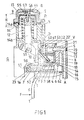
- G denotes the housing of a soap dispenser.
- a storage container V filled with an aqueous soap solution, the lower part of which extends into the housing G and via chamber-like others since!; - h-- storage container and via a feed 6 with a cylinder space 4 of a soap solution metering pump 3 connected is.
- a piston 2 with a cylindrical blind bore and a piston outlet opening 7 ' is arranged in the soap solution metering pump 3. This piston 2 is designed like a slide and sealed on one side by means of an O-ring 52.
- a bearing journal 50 is inserted through the end part of the piston 2 and is inserted non-positively on its two end sides in a drive bracket 1a.
- the cylinder space 4 is connected to a mixing chamber 8 via a connection opening 7.
- the end of a line 18 projects through the lower part of the mixing chamber 8, through which a compressed air D flows in via a compressed air line 5 and can exit via holes 19.
- the compressed air is generated by actuating the lever 1 by means of a force F in a diaphragm pump 9.
- the cylinder 13 of this diaphragm pump 9 has a diaphragm 14a made of rubber which is guided through a diaphragm piston 14 and which is centered on the diaphragm piston 14 by means of a screwed diaphragm holder 59.
- a reaction spring 12 is placed around a piston rod 14b and presses the membrane piston 14 and the actuating elements connected to it into the drawn upper position.
- the membrane piston 14 can experience a maximum stroke H (downward) and draws air through an air inlet 56 and a flap valve 55 into the cylinder 13.
- the flap valve 55 is made of rubber and is fixed on one side by a holder 57 in the cover of the cylinder 13.
- the cylinder space 4 is filled with soap solution except for a small, defined dead space 15, which is essentially predetermined by a bag space 16. If the actuating lever 1 is pressed, the slide-like piston 2 moves to the end of the cylinder space 4 and thereby generates an air cushion 17 by means of the air in the dead space 15 and sack space 16, as a result of which the soap solution is now under pressure and this in the end position of the piston 2 is pressed into the mixing chamber 8 via the piston outlet opening 7 ', the connecting opening 7 and a flap valve 54 which is open in the process.
- the compressed air D flows into the mixing space 8 in the manner mentioned and produces a coarse-bubble foam there, which is pressed through a porous body 20, a so-called frit, and finally flows through an outlet opening A through a subsequent expansion space 21 in a foam deflection body 22 and is available here as a fine, walnut-sized soap foam for cleaning purposes.
- the axes 10 and 11 of the pistons 2 and 14 are perpendicular to each other.
- FIG. 1 also shows closures 62 of mounting bores and a recess 23 for mounting purposes. Furthermore, the foam deflecting body 22 has a centering nose 22 ′ and an O-ring seal 53.
- the flap valve 54 is made of synthetic rubber and centered on the edge side by a partially circumferential retaining ring 58.
- the membrane 14a is preferably a so-called. Roll membrane without fabric based on acrylonitrile butadiene rubber (Carl Freudenberg, D-6101 Reichelsheim).
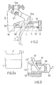
- Fig. 2 is the actuation mechanism with its individual parts can be seen in more detail.
- the actuating lever 1 is configured with two arms and has a bearing pin 50a on the outside of its kink, while in its interior, in a recess 1 ′′ shown in FIG in turn, a bearing pin 50 is pushed through which the force is transmitted to the piston 2.
- an actuating force F leads to a sectoral rotary movement of the actuating lever 1 and pulls the diaphragm piston 14, not shown, over its piston rod 14b and the bearing pin 51 inserted through it.
- the piston 2 is brought into its front end position by a much lower force which is transmitted to the piston 2 via the pin 50 'and the drive bracket 1 and the further bearing pin 50.
- FIG. 3 shows an actuating lever 1b, which leads to a wall-mounted soap dispenser - not shown - and is longer and narrower than FIGS. 1 to 2a and is carried out in masonry M.
- a guide bush 63 is embedded in the masonry M, which has a slot 63 'for the actuating lever 1b and in the interior of which a pin 64, which is cambered on one side, is slidably arranged.
- the pin 64 has a blind hole 65, into which the end of the actuating lever 1 projects and through which a rotatable pin 66 is inserted. If a force F now appears on the pin 64 in the manner shown, the actuating lever 1b comes into operation in the manner described above. In this case too, the return spring 12 described above takes over the resetting of the actuating lever 1b and of the pin 64.
- This variant has the advantage of being able to be actuated away from the actual device; it is particularly suitable for hygienic foot control. 4 two heaters are integrated, which allow the formation of warm soap foam and are mainly used for shaving purposes.
- a heater 29 is arranged in the compressed air line 5 and heats the flowing compressed air D before it enters the mixing chamber 8.
- a continuous-flow heater 33 is provided, which heats the emerging soap foam.
- the heater 29 and the water heater 33 are preferably operated by means of a non-hazardous heating voltage UH of 12 to 24 volts.
- a microswitch 34 which is shown in the switched-off state and whose function is determined by the upper end of the actuating lever 1, is used for the timely switching of this voltage UH.
- the terminal connections marked with plus and minus can of course also be supplied with AC voltage and can be routed via thermostatic or electronic switches and delay elements. Instead of electromechanical switching elements, electro-optical (light barriers) can also be used. Furthermore, the heating can be switched on and / or off by means of room lighting or room ventilation via relays.
- the heater 29 for preheating the air has proven to be particularly advantageous, since it has approximately 15 times the volume fraction in the finished soap foam compared to the soap solution.
- FIG. 5 Another variant serving to preheat the soap solution can be seen in FIG. 5.
- the storage container V which is designed like a chamber on both side surfaces of the housing G, contains a feed line 30 leading from a hot water source B (boiler) to a hot water tap 31 (mixing tap) - or a bypass thereof.
- a lamellar heat exchanger 32 which is placed on the feed line 30, serves to improve the heat dissipation to the soap solution.
- a tensioning device 28 (pneumatic, hydraulic, electrical or electromechanical) is arranged obliquely in such a way that its maximum force F 'in one end position of the lever 1 - reaction spring 12 tensioned - develops a maximum torque.
- FIG. 5a A practical exemplary embodiment in connection with a tensioning device 28 acting on a pressure P 'is shown in FIG. 5a.
- a hydraulic cylinder 28 'with a footrest 24 is embedded in a masonry M and generates the pressure P' required for actuating the tensioning device 28.
- FIG. 5b shows a roller 27 mounted in masonry M, which can be rotated by means of a further footrest 24 'and supplies the force F "required for actuating the lever 1 in the cable 25 via the cable 25.
- All of the exemplary embodiments require little space and can be integrated into the housing of conventional soap dispensers or combined with them.
- the molded parts of the device are advantageously produced by injection molding from thermosetting plastic.
- the compressed air could also be preloaded by other pneumatic aids (C0 2 capsules, rotating small compressor, etc.).
- the invention makes it possible to make washing and shaving opportunities hygienic and economical.
- the consumption of soap or soap solution is considerably reduced compared to the known product due to the high proportion of air in the finished soap foam, which on the one hand less pollutes the waste water and on the other hand no ozone-depleting propellant gas enters the atmosphere.
Landscapes
- Health & Medical Sciences (AREA)
- Public Health (AREA)
- Containers And Packaging Bodies Having A Special Means To Remove Contents (AREA)
- Detergent Compositions (AREA)
- Nozzles (AREA)
Description
- Die vorliegende Erfindung bezieht sich auf ein Gerät zur Bildung von Seifenschaum mit einer durch einen Hebel betätigten Seifenlösungs-Dosiervorrichtung und mit eingebauter Vorrichtung zur Verdichtung und Einführung von Druckgas bzw. Druckluft, die über verschließbare Öffnungen und/oder Leitungen in eine Mischkammer münden und wobei das Gerät wenigstens einen Vorratsbehälter für eine Seifenlösung enthält.
- Seifenspender finden bekanntlich in einer Vielzahl von Ausführungen Einsatz bei öffentlichen und privaten Waschgelegenheiten. Bekannt sind u. a. schaumbildende Seifenspender, welche ein Treibgas aus Dichlordifluormethan (Freon 12) verwenden und deren Verbreitung aus Umweltschutzgründen nur mit großer Zurückhaltung erfolgen darf.
- Aus der US-PS 2 871 058 ist ein Seifenschaumspender bekannt der eine Mischkammer, eine diese beschickende, durch einen Hebel betätigte Seifenlösungs-Dosiervorrichtung sowie eine eingebaute handbetätigte Vorrichtung für die Verdichtung und Einführung von Druckluft in die Mischkammer aufweist. Das Ventil dient zum Verschließen der Druckluftleitung. Die Seifenlösung wird in einem Behälter bevorratet. Der bekannte Spender enthält ferner eine Heizung.
- Diese Einrichtung weist einen großen Raumbedarf auf und erfordert ein regelmäßiges Auswechseln des Druckgasbehälters.
- Es ist Aufgabe der im Anspruch 1 angegebenen Erfindung, ein Gerät zu schaffen, welches umweltfreundlich ist, nur einen geringen Raumbedarf erfordert, vielseitig anwendbar ist und kein Auswechseln einer austauschbaren Druckgasquelle erfordert.
- Die obengenannte Aufgabe wird bei einem Gerät der eingangs genannten Art dadurch gelöst, daß die Seifenlösungs-Dosiervorrichtung eine Dosierpumpe mit einem in einem Zylinderraum angeordneten, von dem Hebel hin- und herbewegbaren Kolben ist und daß der Hebel zusätzlich mechanisch gegenseitig beweglich mit der Vorrichtung für die Verdichtung und Einführung des Druckgases bzw. der Druckluft verbunden ist und diese betätigt.
- Vorteilhafte Weiterbildungen der Erfindung sind in den Unteransprüchen beschrieben.
- Mit dem Gerät nach Anspruch 2 läßt sich die maximale Dosiermenge portionenweise begrenzen; die Schaumbildung nach jeder Hebelbetätigung ist reproduzierbar und unabhängig von der Betätigungsgeschwindigkeit des Hebels.
- Die Ausgestaltung nach Anspruch 3 ergibt eine besonders einfache und wartungsfreie Druckluftquelle.
- Die Ausgestaltung nach Anspruch 4 ist besonders raumsparend und ergibt einen kinematisch günstigen Bewegungsablauf im Antriebsmechanismus beider Pumpen.
- Die Variante nach Anspruch 5 weist den Vorteil auf, daß die Rückbewegung und damit die Druckbildung mit daraus resultierender Schaumbildung durch die Rückwirkfeder erfolgt und somit konstant und unabhängig von der Bedienungsperson ist.
- Die Ausgestaltung nach Anspruch 6 erlaubt die Erzielung von besonders günstigen Volumen-Verhältnissen von Seifenlösung zu Luft von etwa 1 : 15 im Schaum.
- Die Ausführungsform nach Anspruch 7 wirkt als Gasfeder für die Seifenlösung und bewirkt ein rasches Ausfließen der Seifenlösung aus der Dosiervorrichtung in die Mischkammer.
- Durch eine Ausgestaltung nach Anspruch 8 ergibt sich ein Eintauchen der Eintrittsöffnung oder Leitung in die dosierte Seifenlösung, wodurch eine starke Blasenbildung entsteht.
- Die Weiterbildung nach Anspruch 9 ergibt den Vorteil einer großen Anzahl kleinerer Blasen.
- Mit der Ausgestaltung nach Anspruch 10 werden die Blasen zu einen homogenen Schaum von hoher Dichte umgeformt.
- Die Ausführungsform nach Anspruch 11 erlaubt dem durch den porösen Körper hindurchtretenden Schaum ein freies Ausdehnen, wodurch sich auch bei späterer nochmaliger Verdichtung auf einen kleineren Ausflußquerschnitt eine gleichmäßig hohe Schaumqualität ergibt.
- Die Ausgestaltung nach Anspruch 12 ist fabrikationstechnisch günstig und sehr servicefreundlich.
- Ein nach Anspruch 13 ausgebildeter Betätigungshebel erlaubt eine vielseitige Verwendung des Gerätes und erfordert nur geringe Betätigungskräfte.
- Die Weiterbildung nach Anspruch 14 weist den Vorteil auf, daß die bei der Betätigung aufgewandte Kraft vornehmlich für die spätere Komprimierung der Luft in der Membranpumpe zur Verfügung steht.
- Eine weitere Ausgestaltung nach Anspruch 15 ist besonders günstig für einen Einsatz im privaten Bereich.
- Die Ausführungsform nach Anspruch 16 gewährleistet einwandfreie hygienische Verhältnisse auch bei einem Einsatz in öffentlichen Toiletten oder anderen von vielen Personen benutzten Waschgelegenheiten.
- Die Ausgestaltung nach Anspruch 17 erlaubt eine bequeme Montage und Handhabung und ist ebenfalls für viel benutzte Waschgelegenheiten vorgesehen.
- Eine nach Anspruch 18 gestaltete Ausführungsform bringt den Vorteil eines noch höheren Bedienungskomfortes.
- Die Variante nach Anspruch 19 eignet sich vorzüglich zum Einsatz in Coiffeursalons etc Durch Vorwärmung der Seifenlösung und/oder der zugeführten Luft kann der Seifenschaum optimal erwärmt werden.
- Die weitere Ausführungsform nach Anspruch 20 ist energetisch besonders vorteilhaft.
- Eine vorteilhafte Weiterbildung einer energiesparenden Lösung ist in Anspruch 21 beschrieben.
- Eine andere Variante nach Anspruch 22 weist den Vorteil weiterer, dem jeweiligen Einsatz angepaßter Konstruktionsmöglichkeiten der Einrichtung auf.
- In den nachfolgenden Zeichnungen sind Ausführungsbeispiele des Erfindungsgegenstandes dargestellt.
- Es zeigt
- Fig. 1 eine bevorzugte Ausführungsform eines Seifenspenders in Schnittdarstellung,
- Fig. 2 eine Darstellung des Betätigungsmechanismus der Einrichtung gemäß Fig. 1,
- Fig. 2a den Handgriff des Betätigungshebels aus Fig. 1 und 2,
- Fig. 3 eine Variante eines Betätigungshebels für Fußbedienung,
- F i g. 4 eine Einrichtung zur Bildung von warmem Seifenschaum mit einer elektrischen Heizung zur Luftvorwärmung und einem elektrischen Durchlauferhitzer für den Seifenschaum und
- F i g. 5 eine weitere Variante mit Heißwasser-Wärmeaustauscher im Seifenlösungs-Vorratsbehälter und zwei in die Figur integrierte Beispiele einer Fußbedienung gemäß F i g. 5a und Fig. 5b.
- In der Fig. ist mit G das Gehäuse eines Seifenspenders bezeichnet. Aus dem Gehäuse G ragt ein Betätigungshebel 1 mit einem Handgriff 1'. Über dem Gehäuse G ist ein Vorratsbehälter V, mit wäßriger Seifenlösung gefüllt, angeordnet, dessen unterer Teil ins Gehäuse G reicht und über kammerartige weitere seit!;--h-- Vorratsbehälter und über eine Zuführung 6 mit einem Zylinderraum 4 einer Seifenlösungs-Dosierpumpe 3 verbunden ist. In der Seifenlösungs-Dosierpumpe 3 ist ein Kolben 2 mit einer zylindrischen Sacklochbohrung und einer Kolbenaustrittsöffnung 7' angeordnet. Dieser Kolben 2 ist schiebeartig ausgebildet und einseitig mittels eines O-Rings 52 abgedichtet. Durch das Endteil des Kolbens 2 ist ein Lagerzapfen 50 gesteckt, welcher auf seinen beiden Endseiten in einem Antriebsbügel 1a kraftschlüssig eingesetzt ist. Der Zylinderraum 4 ist über eine Verbindungsöffnung 7 mit einer Mischkammer 8 verbunden. In den unteren Teil der Mischkammer 8 ragt das Ende einer Leitung 18, durch welches eine Druckluft D über eine Druckluft-Leitung 5 einströmt und über Löcher 19 austreten kann.
- Die Druckluft wird durch Betätigen des Hebels 1 mittels einer Kraft F in einer Membranpumpe 9 erzeugt. Der Zylinder 13 dieser Membranpumpe 9 weist eine durch einen Membrankolben 14 geführte Membrane 14a aus Gummi auf, welche durch eine verschraubte Membranhalterung 59 auf dem Membrankolben 14 zentriert ist. Eine Rückwirkfeder 12 ist um eine Kolbenstange 14b gelegt und drückt den Membrankolben 14 sowie die damit verbundenen Betätigungsorgane in die gezeichnete obere Lage.
- Der Membrankolben 14 kann einen maximalen Hub H (nach unten) erfahren und zieht dabei Luft über einen Lufteintritt 56 und ein Klappenventil 55 in den Zylinder 13. Das Klappenventil 55 ist aus Gummi gefertigt und einseitig durch eine Halterung 57 im Deckel des Zylinders 13 fixiert.
- Wird nun nicht mehr auf den Hebel 1 gedrückt, d. h. die Kraft F hört auf zu wirken, so bewegt sich der Membrankolben 14 relativ rasch unter dem Einfluß seiner Rückwirkfeder 12 in die obere, gezeichnete Lage. Dabei wird das Klappenventil 55 geschlossen und eine Druckluft D erzeugt, welche über die Druckluft-Leitung 5, gebildet aus Verbindungskanälen auf eine durch eine Ventilfeder 61 vorgespannte Kugel 60 einwirkt und die Druckluft D über die Leitung 18 und die Löcher 19 in die Mischkammer 8 einströmen läßt.
- In der gezeichneten Ruhelage ist der Zylinderraum 4 bis auf einen kleinen, definierten Totraum 15, welcher im wesentlichen durch einen Sackraum 16 vorbestimmt ist, mit Seifenlösung gefüllt. Wird der Betätigungshebel 1 gedrückt, so bewegt sich der schieberartige Kolben 2 bis ans Ende des Zylinderraumes 4 und erzeugt dabei mittels der im Totraum 15 und Sackraum 16 befindlichen Luft ein Luftpolster 17, wodurch die Seifenlösung nun unter Druck steht und diese in der Endstellung des Kolbens 2 über die Kolbenaustrittsöffnung 7', die Verbindungsöffnung 7 und ein hierbei geöffnetes Klappenventil 54 in den Mischraum 8 gepreßt wird.
- Jetzt strömt die Druckluft D in besagter Weise in den Mischraum 8 ein und erzeugt dort einen grobblasigen Schaum, welcher durch einen porösen Körper 20, einer sogenannten Fritte, gepreßt wird und über einen nachfolgenden Expansionsraum 21 in einem Schaumumlenkkörper 22 schließlich durch eine Austrittsöffnung A strömt und hier als feiner, walnußgroßer Seifenschaum für Reinigungszwecke zur Verfügung steht.
- In dieser Einrichtung stehen die Achsen 10 und 11 der Kolben 2 und 14 einander senkrecht gegenüber. Die Kraftübertragung vom Hebel 1, welcher zweiarmig ausgeführt ist, erfolgt über Lagerzapfen 50 und 51 auf einen auf einen Antriebsbügel 1a bzw. auf die Kolbenstange 14b.
- Aus Fig. 1 sind ferner Verschlüsse 62 von Montagebohrungen sowie eine Ausnehmung 23 für Montagezwecke ersichtlich. Im weiteren weist der Schaumumlenkkörper 22 eine Zentriernase 22' sowie eine O-Ring-Dichtung 53 auf. Das Klappventil 54 ist aus synthetischem Kautschuk gefertigt und durch einen teilweise umlaufenden Haltering 58 randseitig zentriert.
- Sämtliche Teile sind aus handelsüblichen Werkstoffen gefertigt; als poröser Körper 20 hat sich eine Fritte aus PTFE (Polytetrafluoräthylen) bewährt. Die Membrane 14a ist vorzugsweise eine sogenannte. Rollmembrane ohne Gewebe auf der Basis von Acrylnitril-Butadien-Kautschuk (Fa. Carl Freudenberg, D-6101 Reichelsheim).
- In den folgenden Zeichnungen sind für gleiche Teile gleiche Bezugszeichen gewählt.
- In einem Teilschnitt, Fig. 2 ist der Betätigungsmechanismus mit seinen Einzelteilen näher ersichtlich. Der Betätigungshebel 1 ist zweiarmig ausgestaltet und weist an seiner Knickstelle außenseitig je einen Lagerzapfen 50a auf, während in seinem Inneren, in einer in Fig. 2a ersichtlichen Ausnehmung 1" über je zwei weitere randseitig angeordnete Zapfen 50' ein Antriebsbügel 1a gelagert ist, in welchem seinerseits ein Lagerzapfen 50 durchgesteckt ist, über den die Kraftübertragung zum Kolben 2 erfolgt.
- Wie aus der Zeichnung ersichtlich ist, führt eine Betätigungskraft F zu einer sektoriellen Drehbewegung des Betätigungshebels 1, und zieht den nicht dargestellten Membrankolben 14 über seine Kolbenstange 14b und den durch diese hindurchgesteckten Lagerzapfen 51 nach unten. Gleichzeitig wird durch eine weit geringere Kraft, welche über den Zapfen 50' und den Antriebsbügel 1 und den weiteren Lagerzapfen 50 auf den Kolben 2 übertragen wird, dieser in seine vordere Endlage gebracht.
- Aus Fig. 2a ist außerdem die Betätigungsfläche 1', welche für eine Handbetätigung ausgebildet ist, näher ersichtlich.
- Die Fig. 3 zeigt einen Betätigungshebel 1b, welcher zu einem an der Wand montierten Seifenspender - nicht dargestellt - führt und gegenüber Fig. 1 bis 2a länger und schmäler ist und in einem Mauerwerk M durchgeführt wird. Im Mauerwerk M ist eine Führungsbüchse 63 eingelassen, welche einen Schlitz 63' für den Betätigungshebel 1b aufweist und in deren Inneren ein einseitig bombierter Zapfen 64 gleitfähig angeordnet ist. Der Zapfen 64 weist eine Sacklochbohrung 65 auf, in welcher das Ende des Betätigungshebels 1 hineinragt und durch welche ein drehfähiger Zapfen 66 durchgesteckt ist. Tritt nun eine Kraft F in gezeichneter Weise auf den Zapfen 64, so tritt der Betätigungshebel 1 b in oben beschriebener Weise in Funktion. Die Rückstellung des Betätigungshebels 1b und des Zapfens 64 übernimmt auch in diesem Fall die vorstehend beschriebene Rückwirkfeder 12.
- Diese Variante hat den Vorteil einer von der eigentlichen Einrichtung entfernten Betätigungsmöglichkeit; sie eignet sich insbesondere für eine hygienisch einwandfreie Fußbetätigung. In die Einrichtung nach Fig. 4 sind zwei Heizungen integriert, welche die Bildung von warmem Seifenschaum erlauben und vornehmlich für Rasierzwecke eingesetzt werden.
- Ein Heizkörper 29 ist dabei in der Druckluft- Leitung 5 angeordnet und wärmt die durchströmende Druckluft D vor ihrem Eintritt in die Mischkammer 8. Als zweite Variante ist ein Durchlauferhitzer 33 vorgesehen, welcher den austretenden Seifenschaum erhitzt.
- Vorzugsweise werden der Heizkörper 29 und der Durchlauferhitzer 33 mittels einer ungefährlichen Heizspannung UH von 12 bis 24 Volt betrieben. Zur zeitgerechten Schaltung dieser Spannung UH dient ein Mikroschalter 34, welcher im ausgeschalteten Zustand dargestellt ist und dessen Funktion durch das obere Ende des Betätigungshebels 1 bestimmt ist.
- Die mit Plus und Minus bezeichneten Klemmenanschlüsse können selbstverständlich auch mit Wechselspannung gespeist werden und über thermostatische oder elektronische Schalter und Verzögerungsglieder geführt sein. Anstelle elektromechanischer Schaltelemente können auch elektrooptische (Lichtschranken) treten. Ferner kann die Heizung durch eine Raumbeleuchtung oder Raumlüftung über Relais ein- und/oder ausgeschaltet werden.
- Als besonders vorteilhaft hat sich dabei der Heizkörper 29 zur Vorwärmung der Luft erwiesen, da diese im fertigen Seifenschaum gegenüber der Seifenlösung den ca. 15fachen Volumenanteil aufweist.
- Eine weitere einer Vorwärmung der Seifenlösung dienende Variante ist aus Fig. 5 ersichtlich. Der an beiden Seitenflächen des Gehäuses G kammerartig ausgebildete Vorratsbehälter V enthält eine von einer Heißwasserquelle B (Boiler) zu einer Heißwasserzapfstelle 31 (Mischhahn) führende Zuleitung 30 - oder einen Bypaß davon. Zur verbesserten Wärmeabgabe an die Seifenlösung dient ein lamellenartiger Wärmeaustauscher 32, welcher auf die Zuleitung 30 aufgesetzt ist.
- In der Fig. 5 sind ferner symbolisch verschiedenartige Antriebsmechanismen für eine Fußbetätigung des Hebels 1 aufgezeigt. Eine Spannvorrichtung 28 (pneumatisch, hydraulisch, elektrisch oder elektromechanisch) ist derart schräg angeordnet, daß ihre maximale Kraft F' in der einen Endlage des Hebels 1 - Rückwirkfeder 12 gespannt - ein maximales Drehmoment entwikkelt.
- Als weitere Möglichkeit ist im unteren Endbereich des Hebels 1 der Einsatz eines Seilzuges 25 mit einer Umlenkrolle 26 eingezeichnet.
- Ein praktisches Ausführungsbeispiel in Verbindung mit einer auf einen Druck P' wirkenden Spannvorrichtung 28 ist in Fig. 5a gezeichnet. Ein Hydraulikzylinder 28' mit einer Fußraste 24 ist in einem Mauerwerk M eingelassen und erzeugt den für die Betätigung der Spannvorrichtung 28 erforderlichen Druck P'.
- Alternativ hierzu ist in Fig. 5b eine in einem Mauerwerk M gelagerte Rolle 27 dargestellt, welche durch eine weitere Fußraste 24' drehbar ist und über den Seilzug 25 die zur Betätigung des Hebels 1 erforderliche Kraft F" im Seilzug 25 liefert.
- Sämtliche Ausführungsbeispiele weisen einen geringen Raumbedarf auf und können in die Gehäuse von konventionellen Seifenspendern integriert bzw. mit diesen kombiniert werden. Die Formteile der Einrichtung werden vorteilhaft in Spritzgußverfahren aus thermohärtendem Kunststoff hergestellt.
- Zur Verringerung der am Betätigungshebel 1 aufzubringenden Kraft F könnte die Druckluft auch durch andere pneumatische Hilfsmittel (C02-Kapseln, rotierender Kleinkompressor, etc.) vorgespannt werden.
- Durch die Erfindung wird es möglich, Wasch-und Rasiergelegenheiten hygienisch einwandfrei und wirtschaftlich zu gestalten. Zudem ist gegenüber dem Bekannten der Verbrauch an Seife oder Seifenlösung aufgrund des hohen Anteils von Luft im fertigen Seifenschaum beträchtlich reduziert, wodurch einerseits die Abwässer weniger belastet werden und andererseits kein Ozon vernichtendes Treibgas in die Atmosphäre gelangt.
Claims (22)
Priority Applications (1)
| Application Number | Priority Date | Filing Date | Title |
|---|---|---|---|
| AT80810139T ATE6576T1 (de) | 1979-05-10 | 1980-04-28 | Geraet zur bildung von seifenschaum mit einer durch einen hebel betaetigten seifenloesungsdosiervorrichtung. |
Applications Claiming Priority (2)
| Application Number | Priority Date | Filing Date | Title |
|---|---|---|---|
| CH4367/79 | 1979-05-10 | ||
| CH436779A CH636761A5 (de) | 1979-05-10 | 1979-05-10 | Einrichtung zur dosierung und bildung von seifenschaum. |
Publications (2)
| Publication Number | Publication Date |
|---|---|
| EP0019582A1 EP0019582A1 (de) | 1980-11-26 |
| EP0019582B1 true EP0019582B1 (de) | 1984-03-14 |
Family
ID=4274779
Family Applications (1)
| Application Number | Title | Priority Date | Filing Date |
|---|---|---|---|
| EP80810139A Expired EP0019582B1 (de) | 1979-05-10 | 1980-04-28 | Gerät zur Bildung von Seifenschaum mit einer durch einen Hebel betätigten Seifenlösungs-Dosiervorrichtung |
Country Status (8)
| Country | Link |
|---|---|
| US (1) | US4349131A (de) |
| EP (1) | EP0019582B1 (de) |
| AT (1) | ATE6576T1 (de) |
| CA (1) | CA1114786A (de) |
| CH (1) | CH636761A5 (de) |
| DE (2) | DE3066928D1 (de) |
| HK (1) | HK85989A (de) |
| MY (1) | MY8600183A (de) |
Cited By (6)
| Publication number | Priority date | Publication date | Assignee | Title |
|---|---|---|---|---|
| EP0079853A3 (en) * | 1981-11-18 | 1983-06-22 | Cws Ag | Device for the portional formation of soap lather |
| WO1990014037A1 (de) * | 1989-05-16 | 1990-11-29 | Pech, Viktor | Vorrichtung für die portionierte ausgabe eines mediums |
| EP0557243A1 (de) * | 1992-02-21 | 1993-08-25 | Steiner Company International S.A. | Verfahren und Vorrichtung zum portionenweisen Erzeugen von Schaum aus flüssiger Seife |
| US5862954A (en) * | 1994-07-18 | 1999-01-26 | Cws International Ag | Device for producing soap lather and use thereof |
| US5906299A (en) * | 1995-03-29 | 1999-05-25 | Hagleitner Betriebshygiene Ges.M.B.H. & Co. Kg | Soap foam dispenser |
| EP1118301A1 (de) | 2000-01-19 | 2001-07-25 | Cws International Ag | Vorrichtung zur Abgabe von Seifenlösung in einem Spender |
Families Citing this family (31)
| Publication number | Priority date | Publication date | Assignee | Title |
|---|---|---|---|---|
| USRE33564E (en) * | 1981-12-14 | 1991-04-02 | Ballard Medical Products | Foam dispensing device |
| DE3668426D1 (de) * | 1985-01-28 | 1990-03-01 | Earl Wright Co | Schaumerzeuger. |
| US4957218A (en) * | 1986-07-28 | 1990-09-18 | Ballard Medical Products | Foamer and method |
| US5339988A (en) | 1992-10-19 | 1994-08-23 | Ballard Medical Products | Disposable tray sump foamer, assembly and methods |
| DE9407178U1 (de) * | 1994-05-02 | 1994-07-07 | Reidel, Hermann, 63791 Karlstein | Vorrichtung zur Erzeugung und Abgabe von Schaum |
| US5725129A (en) * | 1995-06-06 | 1998-03-10 | American Sterilizer Company | Dual-container foam dispenser |
| IT1282730B1 (it) * | 1995-06-08 | 1998-03-31 | Steiner Co Int Sa | Dispositivo per alimentare sapone liquido ad un organo schiumogeno |
| US5842607A (en) * | 1996-03-29 | 1998-12-01 | Adam & Eve Enterprises, Inc. | Lather device |
| EP1118389A1 (de) * | 2000-01-19 | 2001-07-25 | Cws International Ag | Verfahren und Vorrichtung zur kontrollierten Schaumabgabe |
| NL1019348C2 (nl) | 2001-11-12 | 2003-05-13 | Bentfield Europ Bv | Schuimdispenser, huis en voorraadhouder daarvoor. |
| NL1020641C2 (nl) | 2001-11-12 | 2003-05-15 | Bentfield Europ Bv | Dispenser voor afgifte van een vloeistof en huis voor een dergelijke dispenser. |
| US7066356B2 (en) | 2002-08-15 | 2006-06-27 | Ecolab Inc. | Foam soap dispenser for push operation |
| US6644516B1 (en) | 2002-11-06 | 2003-11-11 | Continental Afa Dispensing Company | Foaming liquid dispenser |
| US6923346B2 (en) * | 2002-11-06 | 2005-08-02 | Continental Afa Dispensing Company | Foaming liquid dispenser |
| US7201294B2 (en) * | 2003-05-05 | 2007-04-10 | Conair Corporation | Dispensing apparatus for receiving a number of differently sized foam canisters |
| US6840408B1 (en) | 2003-08-25 | 2005-01-11 | Continental Afa Dispensing Company | Air foam pump with shifting air piston |
| US7661562B2 (en) * | 2005-10-11 | 2010-02-16 | Kimberly-Clark Worldwide, Inc. | Micro powered dispensing device |
| US8486050B2 (en) * | 2006-03-17 | 2013-07-16 | Jackey Chiou | Bubble-type nose cleaner |
| US20090057345A1 (en) * | 2007-08-31 | 2009-03-05 | Dukes Stephen A | Fluid dispenser |
| US8261950B2 (en) | 2007-10-22 | 2012-09-11 | Georgia-Pacific Consumer Products Lp | Pumping dispenser |
| US8056768B2 (en) * | 2007-12-28 | 2011-11-15 | Snodgrass David L | Foam pump assembly |
| US8783511B2 (en) * | 2008-04-25 | 2014-07-22 | Ultraclenz, Llc | Manual and touch-free convertible fluid dispenser |
| USD592899S1 (en) | 2008-04-25 | 2009-05-26 | Impact Products Llc | Soap dispenser |
| US8387832B2 (en) * | 2009-03-06 | 2013-03-05 | Gojo Industries, Inc. | Dispenser housing |
| GB2472235B (en) * | 2009-07-29 | 2011-07-06 | Brightwell Dispensers Ltd | Dispensing device with a disposable pump |
| WO2011133077A1 (en) | 2010-04-22 | 2011-10-27 | Sca Hygiene Products Ab | Pump soap dispenser |
| US8550307B2 (en) | 2011-03-31 | 2013-10-08 | Brightwell Dispensers Limited | Dispensing device with a disposable pump |
| US8651328B2 (en) | 2011-07-14 | 2014-02-18 | Georgia-Pacific Consumer Products Lp | Pumping dispenser shield |
| US8814005B2 (en) | 2012-04-27 | 2014-08-26 | Pibed Limited | Foam dispenser |
| US11291285B2 (en) | 2018-09-07 | 2022-04-05 | LTHR, Inc. | Wireless hot shaving cream dispenser |
| AT523899B1 (de) * | 2020-05-27 | 2023-02-15 | Zawo Tec Gmbh | Spender zur Ausgabe eines Desinfektionsmittels |
Family Cites Families (10)
| Publication number | Priority date | Publication date | Assignee | Title |
|---|---|---|---|---|
| US1219364A (en) * | 1915-03-11 | 1917-03-13 | Frank W Adsit | Soap-dispensing machine. |
| GB193523A (en) * | 1921-11-29 | 1923-02-28 | Giovanni Zingali | Improvements in lather generators |
| US1554147A (en) | 1922-07-29 | 1925-09-15 | Wager Robert Hudson | Lather-forming device |
| US1736392A (en) * | 1928-07-12 | 1929-11-19 | Coss Dorris | Pipette |
| US2529365A (en) * | 1947-05-06 | 1950-11-07 | Barksdale George Roy | Liquid soap dispenser |
| US2715045A (en) * | 1951-10-10 | 1955-08-09 | Kenneth C Thompson | Foam producing device |
| US2772029A (en) * | 1955-06-20 | 1956-11-27 | Lucia Jerry S De | Means for filling grease cups on automotive vehicles |
| US2871058A (en) * | 1955-06-24 | 1959-01-27 | Puglia Salvatore | Tonsorial lather dispensers |
| US3250438A (en) * | 1964-06-12 | 1966-05-10 | G H Packwood Mfg Company | Fluent material dispenser with bottletype material container |
| US3712512A (en) * | 1971-04-26 | 1973-01-23 | J Snider | Lather producing machine |
-
1979
- 1979-05-10 CH CH436779A patent/CH636761A5/de not_active IP Right Cessation
-
1980
- 1980-04-17 CA CA350,061A patent/CA1114786A/en not_active Expired
- 1980-04-21 US US06/142,003 patent/US4349131A/en not_active Expired - Lifetime
- 1980-04-28 EP EP80810139A patent/EP0019582B1/de not_active Expired
- 1980-04-28 DE DE8080810139T patent/DE3066928D1/de not_active Expired
- 1980-04-28 AT AT80810139T patent/ATE6576T1/de not_active IP Right Cessation
- 1980-05-09 DE DE19808012672U patent/DE8012672U1/de not_active Expired
-
1986
- 1986-12-30 MY MY183/86A patent/MY8600183A/xx unknown
-
1989
- 1989-10-26 HK HK859/89A patent/HK85989A/xx not_active IP Right Cessation
Cited By (7)
| Publication number | Priority date | Publication date | Assignee | Title |
|---|---|---|---|---|
| EP0079853A3 (en) * | 1981-11-18 | 1983-06-22 | Cws Ag | Device for the portional formation of soap lather |
| WO1990014037A1 (de) * | 1989-05-16 | 1990-11-29 | Pech, Viktor | Vorrichtung für die portionierte ausgabe eines mediums |
| EP0557243A1 (de) * | 1992-02-21 | 1993-08-25 | Steiner Company International S.A. | Verfahren und Vorrichtung zum portionenweisen Erzeugen von Schaum aus flüssiger Seife |
| US5398845A (en) * | 1992-02-21 | 1995-03-21 | Steiner Company, Inc. | Method of and apparatus for dispensing batches of soap lather |
| US5862954A (en) * | 1994-07-18 | 1999-01-26 | Cws International Ag | Device for producing soap lather and use thereof |
| US5906299A (en) * | 1995-03-29 | 1999-05-25 | Hagleitner Betriebshygiene Ges.M.B.H. & Co. Kg | Soap foam dispenser |
| EP1118301A1 (de) | 2000-01-19 | 2001-07-25 | Cws International Ag | Vorrichtung zur Abgabe von Seifenlösung in einem Spender |
Also Published As
| Publication number | Publication date |
|---|---|
| HK85989A (en) | 1989-11-03 |
| CH636761A5 (de) | 1983-06-30 |
| DE3066928D1 (en) | 1984-04-19 |
| MY8600183A (en) | 1986-12-31 |
| EP0019582A1 (de) | 1980-11-26 |
| ATE6576T1 (de) | 1984-03-15 |
| DE8012672U1 (de) | 1980-08-21 |
| US4349131A (en) | 1982-09-14 |
| CA1114786A (en) | 1981-12-22 |
Similar Documents
| Publication | Publication Date | Title |
|---|---|---|
| EP0019582A1 (de) | Gerät zur Bildung von Seifenschaum mit einer durch einen Hebel betätigten Seifenlösungs-Dosiervorrichtung | |
| EP0557243B1 (de) | Verfahren und Vorrichtung zum portionenweisen Erzeugen von Schaum aus flüssiger Seife | |
| EP0771166B1 (de) | Gerät zur bildung von seifenschaum und dessen verwendung | |
| DE60006928T2 (de) | Vorrichtung zum Abgeben und Mischen von Wasser | |
| EP1656161B1 (de) | Verfahren zum verteilen von flüssigen duftstoffen und vorrichtung zur durchführung des verfahrens | |
| DE2225461A1 (de) | Dosierventil | |
| DE2306085A1 (de) | Nachfuellbare spruehvorrichtung | |
| EP0755721A2 (de) | Spender für ein aus zwei Bestandteilen zusammengestelltes flüssiges Medium | |
| EP0495754B1 (de) | Austauschpatrone für Rasiergerät mit Applikator | |
| DE2901433A1 (de) | Verfahren zur abgabe und applikation von fliessfaehigen stoffen | |
| EP0079853B1 (de) | Einrichtung zur portionenweisen Bildung von Seifenschaum | |
| EP2255886B1 (de) | Vorrichtung zum Aufschäumen und Abgeben von Flüssigkeiten | |
| DE2809511A1 (de) | Verfahren und vorrichtung zum abgeben viskoser fliessmittel | |
| DE102018101809A1 (de) | Vorrichtung zum Auspressen eines Lebensmittels aus einer Patrone | |
| DE69708588T2 (de) | BüGELMASCHINE MIT EINEM BüGELEISEN UND EINEM STäNDER | |
| DE3011765C2 (de) | Multispraysystem für kosmetische Behandlung | |
| EP1497083A1 (de) | Elektrogerät mit einem elektrischen leistungselement und einem flüssigkeitskreislauf | |
| WO1990014037A1 (de) | Vorrichtung für die portionierte ausgabe eines mediums | |
| DE3304177C1 (de) | Vorrichtung zum Erzeugen von Schaum,insbesondere fuer Wasch- oder sonstige Reinigungszwecke | |
| DE602004003027T2 (de) | Flüssigkeitssprüher | |
| DE1454200B2 (de) | Ausgabeeinheit fuer kaffeemaschinen | |
| DE1498355A1 (de) | Selbsttaetige Abgabevorrichtung fuer eine Hilfsfluessigkeit | |
| DE2327191A1 (de) | Seifenspender | |
| DE3604256A1 (de) | Vorrichtung zum desinfizieren, reinigen und trocknen der haende | |
| AT216694B (de) | Selbsttätig arbeitende Kaffeemaschine |
Legal Events
| Date | Code | Title | Description |
|---|---|---|---|
| PUAI | Public reference made under article 153(3) epc to a published international application that has entered the european phase |
Free format text: ORIGINAL CODE: 0009012 |
|
| AK | Designated contracting states |
Designated state(s): AT BE CH DE FR GB IT LI LU NL SE |
|
| 17P | Request for examination filed |
Effective date: 19810310 |
|
| ITF | It: translation for a ep patent filed | ||
| GRAA | (expected) grant |
Free format text: ORIGINAL CODE: 0009210 |
|
| RAP1 | Party data changed (applicant data changed or rights of an application transferred) |
Owner name: CWS AG |
|
| AK | Designated contracting states |
Designated state(s): AT BE CH DE FR GB IT LI LU NL SE |
|
| REF | Corresponds to: |
Ref document number: 6576 Country of ref document: AT Date of ref document: 19840315 Kind code of ref document: T |
|
| REF | Corresponds to: |
Ref document number: 3066928 Country of ref document: DE Date of ref document: 19840419 |
|
| ET | Fr: translation filed | ||
| PLBE | No opposition filed within time limit |
Free format text: ORIGINAL CODE: 0009261 |
|
| STAA | Information on the status of an ep patent application or granted ep patent |
Free format text: STATUS: NO OPPOSITION FILED WITHIN TIME LIMIT |
|
| 26N | No opposition filed | ||
| ITTA | It: last paid annual fee | ||
| EPTA | Lu: last paid annual fee | ||
| EAL | Se: european patent in force in sweden |
Ref document number: 80810139.8 |
|
| PGFP | Annual fee paid to national office [announced via postgrant information from national office to epo] |
Ref country code: SE Payment date: 19970326 Year of fee payment: 18 |
|
| PGFP | Annual fee paid to national office [announced via postgrant information from national office to epo] |
Ref country code: LU Payment date: 19970404 Year of fee payment: 18 |
|
| PGFP | Annual fee paid to national office [announced via postgrant information from national office to epo] |
Ref country code: AT Payment date: 19970407 Year of fee payment: 18 |
|
| PGFP | Annual fee paid to national office [announced via postgrant information from national office to epo] |
Ref country code: NL Payment date: 19970430 Year of fee payment: 18 |
|
| PGFP | Annual fee paid to national office [announced via postgrant information from national office to epo] |
Ref country code: BE Payment date: 19970521 Year of fee payment: 18 |
|
| PG25 | Lapsed in a contracting state [announced via postgrant information from national office to epo] |
Ref country code: LU Free format text: LAPSE BECAUSE OF NON-PAYMENT OF DUE FEES Effective date: 19980428 Ref country code: AT Free format text: LAPSE BECAUSE OF NON-PAYMENT OF DUE FEES Effective date: 19980428 |
|
| PG25 | Lapsed in a contracting state [announced via postgrant information from national office to epo] |
Ref country code: SE Free format text: LAPSE BECAUSE OF NON-PAYMENT OF DUE FEES Effective date: 19980429 |
|
| PG25 | Lapsed in a contracting state [announced via postgrant information from national office to epo] |
Ref country code: BE Free format text: LAPSE BECAUSE OF NON-PAYMENT OF DUE FEES Effective date: 19980430 |
|
| BERE | Be: lapsed |
Owner name: CWS A.G. Effective date: 19980430 |
|
| PG25 | Lapsed in a contracting state [announced via postgrant information from national office to epo] |
Ref country code: NL Free format text: LAPSE BECAUSE OF NON-PAYMENT OF DUE FEES Effective date: 19981101 |
|
| NLV4 | Nl: lapsed or anulled due to non-payment of the annual fee |
Effective date: 19981101 |
|
| EUG | Se: european patent has lapsed |
Ref document number: 80810139.8 |
|
| PGFP | Annual fee paid to national office [announced via postgrant information from national office to epo] |
Ref country code: FR Payment date: 19990421 Year of fee payment: 20 |
|
| PGFP | Annual fee paid to national office [announced via postgrant information from national office to epo] |
Ref country code: GB Payment date: 19990428 Year of fee payment: 20 |
|
| PGFP | Annual fee paid to national office [announced via postgrant information from national office to epo] |
Ref country code: CH Payment date: 19990511 Year of fee payment: 20 |
|
| PGFP | Annual fee paid to national office [announced via postgrant information from national office to epo] |
Ref country code: DE Payment date: 19990623 Year of fee payment: 20 |
|
| PG25 | Lapsed in a contracting state [announced via postgrant information from national office to epo] |
Ref country code: LI Free format text: LAPSE BECAUSE OF EXPIRATION OF PROTECTION Effective date: 20000427 Ref country code: GB Free format text: LAPSE BECAUSE OF EXPIRATION OF PROTECTION Effective date: 20000427 Ref country code: CH Free format text: LAPSE BECAUSE OF EXPIRATION OF PROTECTION Effective date: 20000427 |
|
| REG | Reference to a national code |
Ref country code: CH Ref legal event code: PL |
|
| REG | Reference to a national code |
Ref country code: GB Ref legal event code: PE20 Effective date: 20000427 |