EP0019558B1 - Scherenhebetisch mit Verschiebungsmöglichkeit - Google Patents
Scherenhebetisch mit Verschiebungsmöglichkeit Download PDFInfo
- Publication number
- EP0019558B1 EP0019558B1 EP80400694A EP80400694A EP0019558B1 EP 0019558 B1 EP0019558 B1 EP 0019558B1 EP 80400694 A EP80400694 A EP 80400694A EP 80400694 A EP80400694 A EP 80400694A EP 0019558 B1 EP0019558 B1 EP 0019558B1
- Authority
- EP
- European Patent Office
- Prior art keywords
- branches
- elements
- telescopic
- branch
- length
- Prior art date
- Legal status (The legal status is an assumption and is not a legal conclusion. Google has not performed a legal analysis and makes no representation as to the accuracy of the status listed.)
- Expired
Links
Images

Classifications
-
- B—PERFORMING OPERATIONS; TRANSPORTING
- B66—HOISTING; LIFTING; HAULING
- B66F—HOISTING, LIFTING, HAULING OR PUSHING, NOT OTHERWISE PROVIDED FOR, e.g. DEVICES WHICH APPLY A LIFTING OR PUSHING FORCE DIRECTLY TO THE SURFACE OF A LOAD
- B66F7/00—Lifting frames, e.g. for lifting vehicles; Platform lifts
- B66F7/06—Lifting frames, e.g. for lifting vehicles; Platform lifts with platforms supported by levers for vertical movement
- B66F7/065—Scissor linkages, i.e. X-configuration
-
- B—PERFORMING OPERATIONS; TRANSPORTING
- B66—HOISTING; LIFTING; HAULING
- B66F—HOISTING, LIFTING, HAULING OR PUSHING, NOT OTHERWISE PROVIDED FOR, e.g. DEVICES WHICH APPLY A LIFTING OR PUSHING FORCE DIRECTLY TO THE SURFACE OF A LOAD
- B66F7/00—Lifting frames, e.g. for lifting vehicles; Platform lifts
- B66F7/06—Lifting frames, e.g. for lifting vehicles; Platform lifts with platforms supported by levers for vertical movement
- B66F7/0625—Lifting frames, e.g. for lifting vehicles; Platform lifts with platforms supported by levers for vertical movement with wheels for moving around the floor
-
- B—PERFORMING OPERATIONS; TRANSPORTING
- B66—HOISTING; LIFTING; HAULING
- B66F—HOISTING, LIFTING, HAULING OR PUSHING, NOT OTHERWISE PROVIDED FOR, e.g. DEVICES WHICH APPLY A LIFTING OR PUSHING FORCE DIRECTLY TO THE SURFACE OF A LOAD
- B66F7/00—Lifting frames, e.g. for lifting vehicles; Platform lifts
- B66F7/06—Lifting frames, e.g. for lifting vehicles; Platform lifts with platforms supported by levers for vertical movement
- B66F7/08—Lifting frames, e.g. for lifting vehicles; Platform lifts with platforms supported by levers for vertical movement hydraulically or pneumatically operated
Definitions
- the present invention relates to mobile or fixed devices intended for vertically lifting objects or people, and in particular to mobile devices used at airports to access airplanes with a view to loading or unloading them, the device of the invention being also of the type using two support arms hinged together in the form of scissors.
- Apparatuses of this type currently known are constituted by a platform or a cabin linked to a generally mobile chassis, and which can be raised relative to the latter by means of support arms articulated together constituting Nuremberg scissors and deploying by the action of hydraulic cylinders. In this way, the platform or the cabin can rise to a certain height while remaining parallel to itself during the elevation.
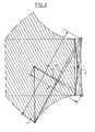
- the branches 3 and 4 of the scissor lift each consist of three telescopic elements (5, 6, 7) and (8, 9, 10) of which the last two elements (6, 7 and 9, 10) always develop of a strictly equal length for each of them.
- each of the branches ( 3, 4) of the pair of scissors are connected together by a horizontal axis 11 located at the intersection of the planes formed by the axes (12, 13) and (14, 15) connecting the ends of the branches (3, 4) respectively to the chassis 1 and to the table 2, these connecting pins being fixed in position relative to the chassis and the table.
- connecting axis 11 of the median elements (6, 9) is at equal distance, on each of the branches 3 and 4, from the connecting axis (respectively 12 and 13) to the chassis 1 and from the connecting axis (respectively 14 and 15) at the lifting table 2.
- FIG. 2 shows the maximum position of the platform 2 assuming the branch 3 not telescoped, and therefore of minimum length I, and the branch 4 completely telescoped, of maximum length L. Furthermore, the area hatched in FIG. 2 represents the area that the platform 2 can occupy in space when the branches 3 and 4 are given all the possible lengths.
- the advantage of the device of the invention in the case of using it to raise a passenger cabin to access an aircraft for example. It is essential that such a cabin remains approximately horizontal during the maneuver or at least parallel to the plane of rest on the chassis. With the device of the invention, it is impossible that it is otherwise, as shown above with reference to Figure 2 and the device allows to cause a longitudinal displacement of the raised cabin, allowing to perfect the adjustment away from it from the plane.
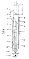
- FIG. 3 shows, by way of indication, a telescopic device with three elements of known type usable for the elevator of the invention.
- This device consists of three telescopic elements (5, 6, 7) whose base element 5 is fixed and the other elements (6, 7) sliding.
- the figure there is shown in solid lines the 'retracted position of the device and in phantom a partially telescoped position thereof.
- a chain 19 is stretched, passing around a pulley 20 adjoining the part upstream of the middle element 6, between a point 21 secured to the downstream part of the base element 5 and a point 22 secured to the upstream part of the last element 7.
- a chain 23 is stretched between point 22 and a point 24 secured to the downstream part of the base element 5; passing around a pulley 25 secured to the downstream part of the middle element 6.
- the rod 17 is released from the jack 16 which, as seen in the drawing, develops the last element 7 of a length (2a) relative to the base element 5.
- the chain 19 then drives simultaneously the development of the middle element 6 of a length (a) relative to the fixed element 5.
- the two movable elements 6 and 7 develop of an equal length (a), the first by relative to the base element 5 and the second relative to the median element 6.
- the chain 23 causes the simultaneous retraction and of the same length of the element 6.
- the invention applies more particularly to mobile vehicles used at airports to access airplanes with a view to loading or unloading them.
Claims (2)
Applications Claiming Priority (2)
| Application Number | Priority Date | Filing Date | Title |
|---|---|---|---|
| FR7913909A FR2457248A1 (fr) | 1979-05-22 | 1979-05-22 | Elevateur-translateur a ciseaux |
| FR7913909 | 1979-05-22 |
Publications (2)
| Publication Number | Publication Date |
|---|---|
| EP0019558A1 EP0019558A1 (de) | 1980-11-26 |
| EP0019558B1 true EP0019558B1 (de) | 1983-11-23 |
Family
ID=9226055
Family Applications (1)
| Application Number | Title | Priority Date | Filing Date |
|---|---|---|---|
| EP80400694A Expired EP0019558B1 (de) | 1979-05-22 | 1980-05-20 | Scherenhebetisch mit Verschiebungsmöglichkeit |
Country Status (5)
| Country | Link |
|---|---|
| US (1) | US4343379A (de) |
| EP (1) | EP0019558B1 (de) |
| JP (1) | JPS55156198A (de) |
| DE (1) | DE3065663D1 (de) |
| FR (1) | FR2457248A1 (de) |
Families Citing this family (13)
| Publication number | Priority date | Publication date | Assignee | Title |
|---|---|---|---|---|
| JPS59118698A (ja) * | 1982-12-24 | 1984-07-09 | 株式会社 彦間製作所 | 昇降装置 |
| US4518061A (en) * | 1983-04-27 | 1985-05-21 | Economy Engineering, Inc. | Translating mobile work platform |
| JPS6019696A (ja) * | 1983-07-09 | 1985-01-31 | 株式会社彦間製作所 | 昇降装置 |
| JPS60118599A (ja) * | 1983-11-29 | 1985-06-26 | 株式会社彦間製作所 | 高所昇降装置 |
| CA1310041C (en) * | 1988-06-14 | 1992-11-10 | John C. Preston | Scaffolding |
| FR2643055B1 (fr) * | 1989-02-15 | 1991-06-28 | Gotlibowicz | Elevateur autoguide |
| US5139110A (en) * | 1990-02-02 | 1992-08-18 | Japanic Corporation | Lifting apparatus |
| JPH0825717B2 (ja) * | 1991-08-30 | 1996-03-13 | 株式会社ジャパニック | 昇降装置の同期機構 |
| US5890864A (en) * | 1997-11-06 | 1999-04-06 | Sloan; Willie Davis | Heavy-duty hay scissors lift |
| US6684443B2 (en) | 2001-02-07 | 2004-02-03 | United Air Lines, Inc. | Multiple-door access boarding bridge |
| US7334804B2 (en) * | 2004-03-12 | 2008-02-26 | Mitchell Knecole A | Portable tire and wheel lifting apparatus |
| DE102006007504A1 (de) * | 2006-02-16 | 2007-08-30 | Hydro-Gerätebau GmbH & Co. KG Hebezeuge | Hebesystem |
| US10156080B1 (en) * | 2017-07-27 | 2018-12-18 | Joaquin Speaks | Boat work platform system and corresponding methods |
Family Cites Families (10)
| Publication number | Priority date | Publication date | Assignee | Title |
|---|---|---|---|---|
| US3125235A (en) * | 1964-03-17 | Load lifting mechanism | ||
| US2003581A (en) * | 1934-09-06 | 1935-06-04 | Jr Charles Daly | Adjustable scaffold |
| DE1080750B (de) * | 1955-05-16 | 1960-04-28 | Wilhelm Ludowici Dr Ing | Hebevorrichtung mit Nuernberger Schere |
| US2984072A (en) * | 1959-01-12 | 1961-05-16 | Hydraulic Engineering Inc | Hydraulic jack assembly with synchronizing and flow equalizing valve mechanism |
| DE1756770A1 (de) * | 1968-07-11 | 1970-04-30 | Trepel Kg Maschinenfabrik | Hydraulisch angetriebener Hebetisch |
| US3598366A (en) * | 1969-04-18 | 1971-08-10 | Milwaukee Hydraulic Products C | Hydraulic jacks for low head room operation |
| US3880259A (en) * | 1973-02-12 | 1975-04-29 | Autoquip Corp | Power apparatus for truck loading elevator |
| US3820631A (en) * | 1973-03-08 | 1974-06-28 | Aircraft Mechanics | Platform lift mechanism |
| US4130178A (en) * | 1977-03-28 | 1978-12-19 | Smith Raymond E Jun | Elevating device |
| NL7705981A (en) * | 1977-05-31 | 1978-12-04 | Verticotrans Anstalt | Heavy load lifting equipment - has main hinging telescopic columns in intersecting pairs actuated by auxiliary ones |
-
1979
- 1979-05-22 FR FR7913909A patent/FR2457248A1/fr active Granted
-
1980
- 1980-05-16 JP JP6517180A patent/JPS55156198A/ja active Pending
- 1980-05-20 EP EP80400694A patent/EP0019558B1/de not_active Expired
- 1980-05-20 DE DE8080400694T patent/DE3065663D1/de not_active Expired
- 1980-05-20 US US06/151,749 patent/US4343379A/en not_active Expired - Lifetime
Also Published As
| Publication number | Publication date |
|---|---|
| FR2457248A1 (fr) | 1980-12-19 |
| DE3065663D1 (en) | 1983-12-29 |
| US4343379A (en) | 1982-08-10 |
| JPS55156198A (en) | 1980-12-04 |
| EP0019558A1 (de) | 1980-11-26 |
| FR2457248B1 (de) | 1984-09-28 |
Similar Documents
| Publication | Publication Date | Title |
|---|---|---|
| EP0019558B1 (de) | Scherenhebetisch mit Verschiebungsmöglichkeit | |
| EP0389378B1 (de) | Hebebühne für Fahrzeuge und Handhabungsverfahren | |
| EP0294278B1 (de) | Unabhängige Aufladevorrichtung für Transportflugzeuge | |
| CA1226258A (fr) | Atterrisseur de type avant pour aeronef | |
| EP0733584A1 (de) | Automatische Aufrichtvorrichtung für einen Kran mit zusammenklappbarem Ausleger | |
| FR2774083A1 (fr) | Dispositif elevateur perfectionne | |
| FR2605619A1 (fr) | Engin repliable pour la manutention et le levage des charges | |
| FR2582977A1 (fr) | Etabli mobile a moyens de manoeuvre exclusivement mecaniques | |
| EP1172323A1 (de) | Kran mit aus Gliedern bestehendem Kranarm | |
| FR2486050A2 (fr) | Appareil de levage comportant une fleche et un contre-poids a positions respectives reglables | |
| FR2476049A1 (fr) | Dispositif de limitation d'un appareillage de levage avec bras a allongement telescopique ou bien articule et telescopique | |
| FR2530604A1 (fr) | Vehicule de manutention a bras orientable et chassis stabilisateur incorpore | |
| EP0049193B1 (de) | Steuervorrichtung für eine klappbare und einziehbare hydraulische Hebebühne für Fahrzeuge | |
| EP0892758B1 (de) | Vorrichtung zum ziehen und drucken von einer last in eine gewisse ebene | |
| EP0490798B1 (de) | Kran, insbesondere für die Handhabung | |
| EP0048199A1 (de) | Vorrichtung zum Schliessen und Öffnen von Lukendeckeln | |
| FR2792022A1 (fr) | Parasol et son dispositif d'aide au deploiement et reploiement | |
| FR2527581A1 (fr) | Plate-forme d'acces | |
| FR2553368A1 (fr) | Appareil de transport | |
| EP0362063B1 (de) | Brückenlegefahrzeug | |
| FR2761970A1 (fr) | Dispositif de relevage de mat pour grue a tour telescopique | |
| FR2910579A1 (fr) | Dispositif de poussee a pantographe | |
| FR2828183A1 (fr) | Colonne telescopique, notamment pour installation de maintenance d'avion | |
| FR2994169A1 (fr) | Engin de levage | |
| FR2707947A1 (fr) | Train d'atterrissage d'aéronef, du type à relevage latéral. |
Legal Events
| Date | Code | Title | Description |
|---|---|---|---|
| PUAI | Public reference made under article 153(3) epc to a published international application that has entered the european phase |
Free format text: ORIGINAL CODE: 0009012 |
|
| AK | Designated contracting states |
Designated state(s): DE GB |
|
| 17P | Request for examination filed |
Effective date: 19801215 |
|
| GRAA | (expected) grant |
Free format text: ORIGINAL CODE: 0009210 |
|
| AK | Designated contracting states |
Designated state(s): DE GB |
|
| REF | Corresponds to: |
Ref document number: 3065663 Country of ref document: DE Date of ref document: 19831229 |
|
| PGFP | Annual fee paid to national office [announced via postgrant information from national office to epo] |
Ref country code: DE Payment date: 19840526 Year of fee payment: 5 |
|
| PLBE | No opposition filed within time limit |
Free format text: ORIGINAL CODE: 0009261 |
|
| STAA | Information on the status of an ep patent application or granted ep patent |
Free format text: STATUS: NO OPPOSITION FILED WITHIN TIME LIMIT |
|
| 26N | No opposition filed | ||
| GBPC | Gb: european patent ceased through non-payment of renewal fee | ||
| PG25 | Lapsed in a contracting state [announced via postgrant information from national office to epo] |
Ref country code: DE Effective date: 19860201 |
|
| PG25 | Lapsed in a contracting state [announced via postgrant information from national office to epo] |
Ref country code: GB Effective date: 19881118 |