EP0018879B1 - Réseau de connexion temporel modulaire - Google Patents
Réseau de connexion temporel modulaire Download PDFInfo
- Publication number
- EP0018879B1 EP0018879B1 EP80400502A EP80400502A EP0018879B1 EP 0018879 B1 EP0018879 B1 EP 0018879B1 EP 80400502 A EP80400502 A EP 80400502A EP 80400502 A EP80400502 A EP 80400502A EP 0018879 B1 EP0018879 B1 EP 0018879B1
- Authority
- EP
- European Patent Office
- Prior art keywords
- subscriber
- junctions
- central
- circuit terminal
- mic
- Prior art date
- Legal status (The legal status is an assumption and is not a legal conclusion. Google has not performed a legal analysis and makes no representation as to the accuracy of the status listed.)
- Expired
Links
- 230000011664 signaling Effects 0.000 claims description 14
- 238000012806 monitoring device Methods 0.000 claims 3
- 238000012544 monitoring process Methods 0.000 claims 1
- 238000000034 method Methods 0.000 description 6
- 230000000712 assembly Effects 0.000 description 2
- 238000000429 assembly Methods 0.000 description 2
- 238000010586 diagram Methods 0.000 description 2
- 230000005540 biological transmission Effects 0.000 description 1
- 230000007423 decrease Effects 0.000 description 1
- 230000001419 dependent effect Effects 0.000 description 1
- 238000004519 manufacturing process Methods 0.000 description 1
- 238000005070 sampling Methods 0.000 description 1
Images


Classifications
-
- H—ELECTRICITY
- H04—ELECTRIC COMMUNICATION TECHNIQUE
- H04Q—SELECTING
- H04Q11/00—Selecting arrangements for multiplex systems
- H04Q11/04—Selecting arrangements for multiplex systems for time-division multiplexing
Definitions
- the present invention relates to a modular connection network for time telephone exchanges, using the pulse modulation and coding technique.
- the invention relates more particularly to central offices or small capacity automatic exchanges using concentrator-deconcentrator devices.
- connection networks are made up of complex assemblies of circuits called time switches and space switches which account for a large part of the volume of the exchanges which comprise them.
- these complex assemblies are ill-suited to the production of easily expandable small capacity exchanges.
- connection networks are known for example from documents FR-A-2,386,225 and DE-B-2,454,090. These known connection networks comprise two stages of connection circuits in cascade. Each circuit of a stage is connected to all the circuits of the other stage, while inside a same stage, the circuits are not connected between them.
- connection networks can be reduced by using the concentration techniques which start from the observation that all the subscribers do not use their lines simultaneously and which make it possible to connect to a central office a number of subscribers greater than the total number of network connection connections for this exchange.
- Concentration techniques are implemented using concentrator-deconcentrator devices, one of them, which is the subject of European patent application EP-0018865 published on 12.11.1980, is carried out using time switching matrices known as MTS symmetric time matrices.
- This concentrator-deconcentrator device comprises a centralized part comprising central modules which are composed using symmetrical time matrices and which ensure the connection of the subscribers with a PABX to ensure their communication with the subscribers not dependent on the terminal. subscribers and circuits.
- the present invention provides a modular time connection network for a small capacity telephone exchange which is expandable, and which avoids the use of a conventional centralized connection network.
- this connection network is produced by direct connection of subscriber terminal units and circuits via digital junctions MIC serving two by two these terminal units together.
- the MIC technique consists in sampling the voice signals at a rate of 8 kHz then in quantifying and coding these samples in the form of digital signals in which each sample is represented by a word of eight binary elements.
- Time division multiplexing enables signals from separate subscribers to be transmitted via a single digital MIC junction, such multiplexing conventionally making it possible to obtain 24 or 30 telephone channels per junction (CCITT standards).
- the central module 1 in FIG. 1 included a part 2 relating to concentration and a part 3 relating to deconcentration.
- the inputs of part 2 consist of MIC junctions coming from as many terminal modules referenced 4 to 9, in an exemplary embodiment this number of junctions is six.
- the outputs of part 3 consist of as many MIC junctions back to the terminal modules 4 to 9.
- MIC Se junctions leaving part 2, and MIC Es junctions, at most, entering part 3, are intended for connections with a PABX 10, i.e. for links between terminal units in the case of a central office.
- a PABX 10 i.e. for links between terminal units in the case of a central office.
- small capacity in an exemplary embodiment the respective numbers of junctions Se and Es are equal and varying from 1 to 4.
- Clc junctions at the output of part 2 and Cld junctions at the input of part 3 are available to make local C1 connections between parts 2 and 3, their number is equal to that of the Es and Se junctions in a example of realization.
- a subscriber and circuit terminal unit comprises central modules, divided into two groups, in an exemplary embodiment each unit comprises six central modules.
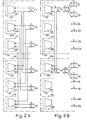
- FIGS. 2A and 2B represent the parts relating to the concentration and deconcentration 101 to 106 of six central modules 107 to 112 distributed in two groups of central modules 113 and 114.
- FIG. 2A six beams F1 to F6 constituted by the MIC junctions Se and Es shown in FIG. 1 are connected to said central modules 107 to 112 so that each beam, such as beam F1, is connected to two central modules, such as central modules 107 and 108, not located in the same group of central modules.
- the central module 107 is located in group 113 and the central module 108 is located in group 114. This, implying that the number of central modules equipped is an even number, is achieved for security reasons .
- traffic can at least partially be passed through the other group of central modules.
- FIG. 2B shows that the beams F1 to F6 which have four junctions each in the chosen example can be split to constitute bundles of 2 junctions f1 to f12.
- the 2 junctions connected to the central module 107 as well as the 2 junctions connected to the central module 108 are shared for security reasons between the beams F1 and F3 so as to constitute 2 beams of 2 junctions f1 to f3.
- n terminal units Three basic configurations for the connection of terminal units are available depending on the number of terminal units to be connected and according to the traffic to be carried, as well as a variant allowing the interconnection of 1 to 10 terminal units.
- the connection between them of n terminal units requires the use of (n-1) bundles per terminal unit, a bundle of 4 junctions capable of carrying traffic of 90 Erlangs and a bundle of 2 junctions 40 Erlangs, these numbers being approximate.
- the bundles F1 to F6 shown in FIG. 2A allow the connection between them of 7 terminal units.
- the law of interconnection of terminal units can be as follows: the beam Fi of the terminal unit Uj (j oi) is connected to the beam Fj of the terminal unit Ui + 1.
- the first configuration relates to the connection, illustrated by the table in Figure 3, of terminal units U1 to U7.
- the number at the top of each column represents the number of terminal units to be connected together.
- a single U1 terminal unit, equipped with 2 central modules, therefore comprising 2 bundles of 4 local junctions each, can carry traffic of 180 Erlangs.
- Two terminal units, U1 and U2 are connected by means of a single beam F1, which is expressed in the table in Figure 3 by F1 U-F1 U2.
- F1 U-F1 U2 the local traffic in each U1 or U2 terminal unit is equal to the traffic to the other unit
- each U1 or U2 terminal unit can carry a total traffic of 180 Erlangs.
- the table in Figure 3 shows the connections that can be made between bundles from the terminal units U1 to U7 to be connected according to the interconnection law set out above.
- the table below shows on the second line the number m1 of central modules per terminal unit and on the third line the total number p1 of 8-pair cables connecting the terminal units together, to be used according to the number n1 of these units listed in First line.
- n1 (2 ⁇ n1 ⁇ 7) terminal units requires the use of (ni -1) bundles of 4 junctions per terminal unit, therefore of m1 central modules per terminal unit, m1 being a even number equal to or immediately greater than (ni -1).
- the total number of cables with 8 pairs i.e. the total number of bundles with 4 junctions connecting the terminal units to each other is equal to the number of combinations of 2 terminal units chosen from n1 units:
- each terminal unit carries the same amount of traffic, let T be this common value of traffic. Because in addition to the (n1-1) bundles of 4 junctions per terminal unit there is a bundle of local connection junctions, each bundle Fi (1 ⁇ i ⁇ 6) carries a traffic equal to . assuming that each Fi bundle as well as the local connection trunk bundle carry the same amount of traffic.
- the table below shows on the second line the number m2 of central modules per terminal unit and, on the third line, the total number p2 of 4-pair cables connecting the terminal units to each other, as a function of the number n2 (5 ⁇ n2 ⁇ 13), appearing on the first line, of terminal units.
- n2 (b ⁇ n2 ⁇ 13) terminal units requires the use of m2 central modules per terminal unit, m2 being equal to 2 ⁇ DE ßE denotes the entire part of the expression.
- m2 being equal to 2 ⁇ DE ßE denotes the entire part of the expression.
- the total number of cables with 4 pairs i.e. the total number of bundles with 2 junctions connecting the terminal units to each other is, as for the first configuration, given by the formula
- a third configuration deals with the case of very traffic terminal units. For a terminal unit, all you have to do is add central modules. But in the case of several terminal units, the bundles Fi of 4 junctions used in the first configuration are insufficient. Thus, for two terminal units, as has been seen previously, the total traffic carried by each terminal unit is at most 180 Erlangs.
- the beams Fi of the first configuration can then be grouped two by two to create 3 beams ⁇ 1 to ⁇ 3 of 8 MIC junctions and each flowing 190 Erlangs.
- Figure 4 shows the diagram of Figure 2A by grouping the 6 beams FI to F6 into beams ⁇ 1 1 to ⁇ 3.
- the 3 bundles ⁇ 1 to ⁇ 3 allow up to 4 terminal units with very high traffic to be connected according to the interconnection law set out above.
- the table below shows in the second line the number m3 of central modules per terminal unit and in the third line the number p3 of cables with 16 pairs between them the terminal units these modules and these cables to be used according to the number n3 1 ⁇ n3 ⁇ 4) of terminal units, listed on the first line.
- a connection variant for 1 to 10 terminal units U1 to U10 can be deduced from the first and second configurations described above. It was found that from 5 units, this for a average value of traffic carried by each unit of 180 Erlangs, the interconnections can be carried out by bundles of 2 junctions. The maximum of 24 MIC junctions from the 6 central modules included in a terminal unit can be grouped, for part of them, into 3 bundles of 4 junctions each and for the other part, into 6 bundles of 2 junctions MIC each.
- FIG. 5 takes up the diagram of FIG.
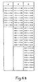
- the table in FIG. 6A shows the connections made between bundles in the case of the connection of 2 to 7 terminal units U1 to U7.
- the table in FIG. 6B presents the additional connections made between bundles in the case of the connection of 8 to 10 units U1 to U10.
- the figure at the top of each column represents the number of terminal units to be connected together according to the general interconnection law set out above.
- Extensions from 1 to 10 terminal units are made by adding cables (8 pairs or 4 pairs) and central modules of the concentrator-deconcentrator device.
- the table below shows, in the second line, the number m4 of central modules per terminal unit and, in the third and fourth lines, the numbers p41 and p42 of 8-pair and 4-pair cables respectively, connecting the U1 terminal units to each other. at U10.
- These numbers m4, p41, p42 are a function of the number n4 of terminal units appearing on the first line of the table.
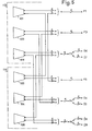
- connection of terminal units by a connection network without a centralized part requires the transmission of messages between terminal units by signaling on a common channel (Figure 7).
- a forward channel and a return channel are reserved on a MIC junction connected to the central module corresponding to the beam.
- this signaling channel is duplicated on another MIC junction of the beam.
- a signaling controller 11 controls the signaling carried by the signaling channels of the beams corresponding to the central modules of the group. For each beam, one of the two signaling controllers controls one of the two channels, the other signaling controller controls the other channel.
- connection of terminal units results in a specific connection network constructed by means of the present invention, the scope of which is defined by the appended claims.
Landscapes
- Engineering & Computer Science (AREA)
- Computer Networks & Wireless Communication (AREA)
- Sub-Exchange Stations And Push- Button Telephones (AREA)
- Telephonic Communication Services (AREA)
- Use Of Switch Circuits For Exchanges And Methods Of Control Of Multiplex Exchanges (AREA)
Applications Claiming Priority (2)
| Application Number | Priority Date | Filing Date | Title |
|---|---|---|---|
| FR7910805A FR2455414A1 (fr) | 1979-04-27 | 1979-04-27 | Reseau de connexion temporel modulaire |
| FR7910805 | 1979-04-27 |
Publications (2)
| Publication Number | Publication Date |
|---|---|
| EP0018879A1 EP0018879A1 (fr) | 1980-11-12 |
| EP0018879B1 true EP0018879B1 (fr) | 1984-04-04 |
Family
ID=9224859
Family Applications (1)
| Application Number | Title | Priority Date | Filing Date |
|---|---|---|---|
| EP80400502A Expired EP0018879B1 (fr) | 1979-04-27 | 1980-04-15 | Réseau de connexion temporel modulaire |
Country Status (7)
| Country | Link |
|---|---|
| US (1) | US4317008A (Direct) |
| EP (1) | EP0018879B1 (Direct) |
| AU (1) | AU5768080A (Direct) |
| BR (1) | BR8002517A (Direct) |
| DE (1) | DE3067315D1 (Direct) |
| FR (1) | FR2455414A1 (Direct) |
| GR (1) | GR68081B (Direct) |
Families Citing this family (1)
| Publication number | Priority date | Publication date | Assignee | Title |
|---|---|---|---|---|
| US6125111A (en) * | 1996-09-27 | 2000-09-26 | Nortel Networks Corporation | Architecture for a modular communications switching system |
Citations (1)
| Publication number | Priority date | Publication date | Assignee | Title |
|---|---|---|---|---|
| EP0018865A1 (fr) * | 1979-04-25 | 1980-11-12 | Thomson-Csf Telephone | Dispositif concentrateur-déconcentrateur |
Family Cites Families (9)
| Publication number | Priority date | Publication date | Assignee | Title |
|---|---|---|---|---|
| US4021619A (en) * | 1974-06-10 | 1977-05-03 | The Post Office | Improved digital telephone and switching system employing time division multiplex pulse code modulation |
| DE2454090C2 (de) * | 1974-11-14 | 1976-09-23 | Siemens Ag | Vierdrahtig durchschaltendes, eine mehrstufige Umkehrgruppierung aufweisendes Koppelfeld |
| US4150258A (en) * | 1975-02-03 | 1979-04-17 | Oki Electric Industry Co., Ltd. | Electronic switching system |
| US4007338A (en) * | 1975-09-18 | 1977-02-08 | Gte Automatic Electric Laboratories Incorporated | Switching and transmission technique using a method and arrangement of channel allocation for providing conferencing |
| FR2327696A1 (fr) * | 1975-10-10 | 1977-05-06 | Labo Cent Telecommunicat | Perfectionnements aux concentrateurs de lignes dans un systeme multiplex dans le temps |
| DE2713610A1 (de) * | 1977-03-28 | 1978-10-05 | Siemens Ag | Pcm-zeitmultiplexkoppelfeld |
| FR2408963A1 (fr) * | 1977-11-10 | 1979-06-08 | Thomson Csf | Dispositif de concentration pour autocommutateur telephonique |
| FR2415407A1 (fr) * | 1978-01-20 | 1979-08-17 | Thomson Csf | Reseau de connexion spatio-temporel |
| FR2429534A1 (fr) * | 1978-06-19 | 1980-01-18 | Cit Alcatel | Reseau de connexion pour multiplex, a qualite de service accrue |
-
1979
- 1979-04-27 FR FR7910805A patent/FR2455414A1/fr active Granted
-
1980
- 1980-04-15 DE DE8080400502T patent/DE3067315D1/de not_active Expired
- 1980-04-15 EP EP80400502A patent/EP0018879B1/fr not_active Expired
- 1980-04-22 AU AU57680/80A patent/AU5768080A/en not_active Abandoned
- 1980-04-24 GR GR61770A patent/GR68081B/el unknown
- 1980-04-24 BR BR8002517A patent/BR8002517A/pt unknown
- 1980-04-25 US US06/143,555 patent/US4317008A/en not_active Expired - Lifetime
Patent Citations (1)
| Publication number | Priority date | Publication date | Assignee | Title |
|---|---|---|---|---|
| EP0018865A1 (fr) * | 1979-04-25 | 1980-11-12 | Thomson-Csf Telephone | Dispositif concentrateur-déconcentrateur |
Also Published As
| Publication number | Publication date |
|---|---|
| DE3067315D1 (en) | 1984-05-10 |
| BR8002517A (pt) | 1980-12-09 |
| EP0018879A1 (fr) | 1980-11-12 |
| GR68081B (Direct) | 1981-10-30 |
| AU5768080A (en) | 1980-10-30 |
| US4317008A (en) | 1982-02-23 |
| FR2455414B1 (Direct) | 1982-04-02 |
| FR2455414A1 (fr) | 1980-11-21 |
Similar Documents
| Publication | Publication Date | Title |
|---|---|---|
| DE69012162T2 (de) | Kommunikationsnetzwerk. | |
| JPH08505270A (ja) | 分配通信ネットワーク | |
| FR2648295A1 (fr) | Aiguilleur a largeur de bande et frequence centrale variables pour satellites multifaisceaux | |
| EP0133703B1 (fr) | Centre satellite numérique de raccordement d'abonnés | |
| DE69017115T2 (de) | System für schnelle Paket- und Frequenzvermittlung. | |
| EP0018879B1 (fr) | Réseau de connexion temporel modulaire | |
| DE69928033T2 (de) | Rekonfigurierbare Verzweigungseinheit für ein Unterseeübertragungssystem | |
| EP0075248B1 (fr) | Dispositif de distribution de signaux pour autocommutateur temporel | |
| EP0062295B1 (fr) | Réseau de connexion numérique | |
| DE69937384T2 (de) | Schalter und Schaltverfahren zum Bearbeiten von Kommunikationsdaten einer bestimmten Verbindung | |
| CA2297298A1 (fr) | Modules de commutation, matrice de commutation comportant de tels modules, et reseau de commutation modulaire non bloquant comportant une telle matrice | |
| BE898424R (fr) | Systeme de telecommunications a integration de services par interconnexion de commutateurs et reseaux specialises. | |
| CA1215483A (fr) | Dispositif de transfert et de traitement de voies de donnees ou de signalisation d'un ensemble de lignes multiplex | |
| DE69730428T2 (de) | Echokompensatorsystem | |
| EP0575369B1 (de) | Digitales kommunikationssystem mit vermittlungstechnischen servern | |
| DE69434920T2 (de) | Anrufabhöranordnung | |
| DE3422219A1 (de) | Optisches nachrichtenuebertragungssystem im teilnehmeranschlussbereich | |
| EP0003448A1 (fr) | Réseau de connexion spatio-temporel | |
| DE3023205A1 (de) | Verbindungseinrichtung fuer ein zeitmultiplex-telefonvermittlungssystem | |
| EP1410650B1 (de) | Telefonsystem und hilfsmittel für das betreiben des systems | |
| RU2041567C1 (ru) | Система коммутации | |
| US5291478A (en) | Switching network wherein short-path connections can be switched | |
| FR2665314A1 (fr) | Reseau d'interconnexion pour cóoeur d'installation de communication et installation dotee d'un tel reseau. | |
| BE1022619B1 (fr) | Répartiteur automatique et procédé pour utiliser celui-ci | |
| RU81023U1 (ru) | Универсальная телекоммуникационная платформа с широкополосным доступом, использующая технологию пассивной оптической сети |
Legal Events
| Date | Code | Title | Description |
|---|---|---|---|
| PUAI | Public reference made under article 153(3) epc to a published international application that has entered the european phase |
Free format text: ORIGINAL CODE: 0009012 |
|
| AK | Designated contracting states |
Designated state(s): BE DE GB IT SE |
|
| 17P | Request for examination filed |
Effective date: 19801208 |
|
| ITF | It: translation for a ep patent filed | ||
| GRAA | (expected) grant |
Free format text: ORIGINAL CODE: 0009210 |
|
| PGFP | Annual fee paid to national office [announced via postgrant information from national office to epo] |
Ref country code: BE Payment date: 19840331 Year of fee payment: 5 |
|
| PGFP | Annual fee paid to national office [announced via postgrant information from national office to epo] |
Ref country code: DE Payment date: 19840402 Year of fee payment: 5 |
|
| AK | Designated contracting states |
Designated state(s): BE DE GB IT SE |
|
| REF | Corresponds to: |
Ref document number: 3067315 Country of ref document: DE Date of ref document: 19840510 |
|
| PGFP | Annual fee paid to national office [announced via postgrant information from national office to epo] |
Ref country code: SE Payment date: 19841231 Year of fee payment: 6 |
|
| PLBE | No opposition filed within time limit |
Free format text: ORIGINAL CODE: 0009261 |
|
| STAA | Information on the status of an ep patent application or granted ep patent |
Free format text: STATUS: NO OPPOSITION FILED WITHIN TIME LIMIT |
|
| 26N | No opposition filed | ||
| PG25 | Lapsed in a contracting state [announced via postgrant information from national office to epo] |
Ref country code: GB Effective date: 19890415 |
|
| PG25 | Lapsed in a contracting state [announced via postgrant information from national office to epo] |
Ref country code: SE Effective date: 19890416 |
|
| PG25 | Lapsed in a contracting state [announced via postgrant information from national office to epo] |
Ref country code: BE Effective date: 19890430 |
|
| BERE | Be: lapsed |
Owner name: THOMSON-CSF TELEPHONE Effective date: 19890430 |
|
| GBPC | Gb: european patent ceased through non-payment of renewal fee | ||
| PG25 | Lapsed in a contracting state [announced via postgrant information from national office to epo] |
Ref country code: DE Effective date: 19900201 |
|
| EUG | Se: european patent has lapsed |
Ref document number: 80400502.3 Effective date: 19900412 |