EP0018382B1 - Connecteur electrique - Google Patents
Connecteur electrique Download PDFInfo
- Publication number
- EP0018382B1 EP0018382B1 EP79900541A EP79900541A EP0018382B1 EP 0018382 B1 EP0018382 B1 EP 0018382B1 EP 79900541 A EP79900541 A EP 79900541A EP 79900541 A EP79900541 A EP 79900541A EP 0018382 B1 EP0018382 B1 EP 0018382B1
- Authority
- EP
- European Patent Office
- Prior art keywords
- wire
- connector
- openings
- housing
- slot
- Prior art date
- Legal status (The legal status is an assumption and is not a legal conclusion. Google has not performed a legal analysis and makes no representation as to the accuracy of the status listed.)
- Expired
Links
Images

Classifications
-
- H—ELECTRICITY
- H01—ELECTRIC ELEMENTS
- H01R—ELECTRICALLY-CONDUCTIVE CONNECTIONS; STRUCTURAL ASSOCIATIONS OF A PLURALITY OF MUTUALLY-INSULATED ELECTRICAL CONNECTING ELEMENTS; COUPLING DEVICES; CURRENT COLLECTORS
- H01R4/00—Electrically-conductive connections between two or more conductive members in direct contact, i.e. touching one another; Means for effecting or maintaining such contact; Electrically-conductive connections having two or more spaced connecting locations for conductors and using contact members penetrating insulation
- H01R4/24—Connections using contact members penetrating or cutting insulation or cable strands
- H01R4/2416—Connections using contact members penetrating or cutting insulation or cable strands the contact members having insulation-cutting edges, e.g. of tuning fork type
- H01R4/2445—Connections using contact members penetrating or cutting insulation or cable strands the contact members having insulation-cutting edges, e.g. of tuning fork type the contact members having additional means acting on the insulation or the wire, e.g. additional insulation penetrating means, strain relief means or wire cutting knives
Definitions
- the present invention relates to an improved electrical connector and, more particularly, to an insulation displacement connector of the type used for terminating a plurality of wires and connecting them to a like plurality of other electrical components.
- Wire-stripping connectors comprising an insulative housing and one or more insulation displacing metallic terminal elements retained by the housing, have become quite popular because of the labor savings they provide in that pre-stripping the insulation from the portion of wire to be terminated is not required.
- a connector as set out in the prior art parts of claim 1 is known from US-Patent 3 778 750.
- US-Patent 3 778 750 By means of several abutment surfaces, namely contact strip and connector block segments, the latter one having fingers with flexible parallel walls and non flexible protrusion pairs this connector is capable of loosely mechanically holding all the wires of only one defined diameter to be terminated in the connectors prior to electrical termination of the wires in the terminal elements. This holding is however not sufficient for wires of smaller diameters, especially if the connector will be displaced to a remote common termination station.
- Connectors known from US-Patent 3 975 812 as well as FR-Patent 2 311 423 have slots through which wires to be terminated are pressed just prior to the moment the metallic terminal element makes contact with the metallic core of the wire. With this the connectors cannot be moved either before termination. A stationary hold of the wires before termination is not forseen, especially not for wires of different diameters.
- connectors constructed as set forth in claim 1 firmly mechanically hold all the wires to be terminated in the connector prior to their electrical termination, so that wires of different diameters can be terminated.
- One of the advantageous effects of the present invention is that a wire harness using the claimed connectors can be completed, except for electrical termination of the wires, at a wiring station and be moved to a remote termination station without the wires becoming disassociated from their corresponding terminal elements.
- a single set of termination equipment can be used to terminate harnesses coming from a plurality of wiring stations.
- Another advantage is, if the connectors are to be terminated at the wiring station, separate wiring jigs for holding the wires in alignment are no longer needed because the connector itself firmly holds the wires in position for termination.
- Another advantage is that the same connector can be used for wires of a range of diameters.
- the connector of the present invention includes an insulative housing having a front wall, a back wall, and a plurality of spaced barrier walls joining the aforementioned walls to define an array of cavities extending through the housing.
- the cavities each receive a metallic terminal element having a wire termination portion and a pin receiving portion.
- the wire terminating portion has an open ended elongate wire receiving slot of a width less than the diameter of the conductor in the wire to be terminated in that wire receiving portion so that in response to the insertion of the wire laterally of its axis into the slot, the insulation of the wire is removed.
- the wire receiving portion also includes an entrance adjoining the slot and of greater width than the slot to guide the wire into the slot.
- the housing and/or the terminal element includes holding means for firmly mechanically holding each of the wires in alignment with the entrance of the slot corresponding to that wire prior to insertion of the wire into the slot.
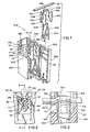
- the connector of the present invention is generally indicated by reference character 32B.
- the upstanding fingers 90B and 92B of front wall 36B and back wall 38B, respectively, defining the pair of aligned wire receiving openings 94B and 96B each have an upper ear 108 extending downwardly into its corresponding opening to define an upper constricted throat 110 thereto.
- Each ear 108 comprises an abutment surface 112 for engaging a wire inserted past the constricted throat to preclude its escape from the opening prior to its electrical termination and constricted throat 110 is of a width less than the diameter of the wire to be inserted.
- Adjacent fingers 90B forming openings in front wall 36B also each have a lower ear 114 extending downwardly into an opening 94B to define a lower constricted throat 116 having a width less than the diameter of a wire 28.
- each lower each 114 has a lower abutment surface 118 for engaging an electrically terminated wire inserted past the lower constricted throat to provide strain relief therefor.
- the lowest portion of each opening 96B in back wall 38B is traversed by an enclosure 120 for protecting the end of a terminated wire after the excess portion of the wire has been trimmed as shown in Figure 5.
- Terminal element 44B has a retaining arm 74B which primarily performs a strain relief function and has a barb-like free end 68B bent to extend upwardly and toward first barrier wall 40-1 B.
- Arm 74B is movable from a first position, shown in Figure 2, wherein it is disposed adjacent first barrier wall 40-1 B so that wire 28 can be inserted into wire receiving slots 54B without interference from the arm to a second position, shown in Figure 4, wherein arm 74B extends across the slots and above the terminated wire with its free end 78B gouging into second barrier wall 40-2B.
- the converging support surfaces 60B, defining entrances 58B to corresponding wire-receiving slots 54B, and the upper housing ears 108 constitute the holding means for firmly mechanically holding wires 28 in alignment with their respective wire-receiving slots prior to their electrical termination.
- the abutment surfaces 112 of ears 108 are positioned relative to support surfaces 60B so that a wire portion 28-1 engaged by the support surfaces is disposed above a wire portion 28-2 engaged by the abutment surfaces whereby, due to its resiliency, the wire 28 is concurrently held in compressive engagement adjacent its bottom by support surfaces 60B and adjacent its top by abutment surfaces 112 prior to its termination in wire-receiving slots 54B.
- the retaining arm die member used for connector 32B preferably has an inclined leading surface with, referring to Figure 2, the lower end of the surface adjacent barrier wall 40-1 B. This will insure that, after termination of the wire by the wire insertion die member, the free end 78B of retaining arm 74B is moved toward second barrier wall 40-2B prior to the arm undergoing permanent deformation.
- a salient advantage of connector 32B is that due to the presence of upper ears 108 disposed on both the front and back walls of the housing, the wire is mechanically held on both sides of the terminal element to prevent a loose end of the wire from interfering with the wire terminating apparatus.
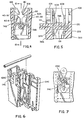
- housing 34C Components of housing 34C similar to previously described components of housing 34B are designated by the suffix "C".
- the primary difference between housing 34C and housing 34B is that the ears 108C and 114C are stronger and more rigid and therefore undergo little deflection during wire insertion and termination.
- wire insertion between pairs of fingers 108C and 114C, respectively requires greater force, this configuration offers increased wire holding strength prior to termination and greater strain relief strength after wire termination.
- the operation of housing 34C is similar to that of housing 34B described above.
- Wire receiving portion 46E of terminal element 44E comprises a pair of spaced links 124 each bridging aligned plate sections 56E of the respective wire-receiving plates 52E. Barrier walls 40E are provided with ledges 125 for supporting links 124. Wire receiving portion 46E further comprises, disposed between front wall 36E and the plate 52E adjacent the front wall, a pair of facing strain relief arms 126 joined to plate 52E by respective cantilevers 128.
- each arm is of generally triangular configuration and has a surface 132 engageable with a like surface of the distal end 130 of the other strain relief arm 126 when the arms are deformed to retain a terminated wire. More specifically, the strain relief arms are movable from first or formed positions wherein one arm is disposed adjacent first barrier wall 40-1 E and the other arm is positioned adjacent second barrier wall 40-2E so that a wire can be inserted into wire receiving slots 54E without interference from the arms to second or deformed positions, as shown in Figure 9, wherein arms 126 extend over a terminated wire 28 to prevent its escape from wire receiving slots 54E and wherein the distal ends 130 are situated side-by-side and in full surface engagement to present a neat appearance. It will be appreciated that a similar set of strain relief arms could be provided between back wall 38E and the wire receiving plate 52E adjacent thereto.
- connector 32E Operation of connector 32E is similar to that of connector 32B above described in that housing ears 108E and wire receiving slot entrance surfaces 60E constitute means for firmly mechanically holding a wire 28 prior to its electrical termination in slots 54E.
- the die unit used with connector 32E has a retaining arm die member which moves strain relief arms 126 to their second positions after wire 28 has been received within slots 54E.
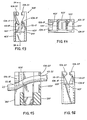
- FIG. 13-16 another connector of the present invention is generally indicated by reference character 32F with components thereof corresponding to components of previously described connectors designated by the suffix "F".
- Front wall ears 108-1 have an abutment surface 112-1 F disposed below the level of the abutment surface 112-2F of back wall ears 108-2F.
- a wire 28 engaging abutment surfaces 112-1 F and 112-2F and support surfaces 60F is bowed so that, due to its resiliency and as shown in Figure 15, it is firmly mechanically held prior to its electrical termination in slots 54F.
- the holding means comprises abutment surfaces 112-1 and 112-2F along with support surface 60F.
- a salient advantage of this embodiment is that front wall abutment surfaces 112-1 serve a dual function in that prior to electrical termination they aid in holding the wire and after termination of the wire they function as strain relief members to prevent the wire from escaping from slots 54F.
- connector 32F Operation of connector 32F is similar to that of other connectors of the present invention described above.
- barrier walls could be provided with protuberances having surfaces which provide the function of support surfaces 60F and in that case the holding means would be constituted exclusively by components of the housing.
- connectors of the present invention have been described for use in terminating a plurality of discrete wires 28, it will be appreciated that the design of the connectors is conducive for use with flat cables of the type wherein an array of parallel, regularly spaced, coplanar conductors are sandwiched between an upper and lower sheet of insulation with insulation between adjacent conductors forming webs. With a transverse row of openings formed in the webs and matching the placement of barrier walls of the connector, the flat cable can be moved laterally of the axes of the conductors with each conductor being received by a corresponding housing cavity 42. With the various conductors held by their associated holding means, the partially completed harness can be moved to a mass wire termination station where the conductors can be terminated.
Abstract
Claims (5)
Applications Claiming Priority (2)
| Application Number | Priority Date | Filing Date | Title |
|---|---|---|---|
| US909732 | 1978-05-25 | ||
| US05/909,732 US4191442A (en) | 1978-05-25 | 1978-05-25 | Electrical connector and method of fabricating a wire harness using the connector |
Publications (3)
| Publication Number | Publication Date |
|---|---|
| EP0018382A4 EP0018382A4 (fr) | 1980-07-08 |
| EP0018382A1 EP0018382A1 (fr) | 1980-11-12 |
| EP0018382B1 true EP0018382B1 (fr) | 1983-05-25 |
Family
ID=25427736
Family Applications (1)
| Application Number | Title | Priority Date | Filing Date |
|---|---|---|---|
| EP79900541A Expired EP0018382B1 (fr) | 1978-05-25 | 1980-01-03 | Connecteur electrique |
Country Status (9)
| Country | Link |
|---|---|
| US (1) | US4191442A (fr) |
| EP (1) | EP0018382B1 (fr) |
| JP (1) | JPS5933937B2 (fr) |
| AU (1) | AU529976B2 (fr) |
| CA (1) | CA1098982A (fr) |
| DE (1) | DE2965492D1 (fr) |
| ES (1) | ES480843A1 (fr) |
| IT (1) | IT1114020B (fr) |
| WO (1) | WO1979001118A1 (fr) |
Cited By (1)
| Publication number | Priority date | Publication date | Assignee | Title |
|---|---|---|---|---|
| DE102015000275A1 (de) * | 2015-01-16 | 2016-07-21 | PanCon GmbH Gesellschaft für elektromechanische Bauelemente | Steckverbinder mit Schneidklemmkontakt |
Families Citing this family (27)
| Publication number | Priority date | Publication date | Assignee | Title |
|---|---|---|---|---|
| US4274696A (en) * | 1979-11-23 | 1981-06-23 | Amp Incorporated | Electrical connecting device for wiring systems |
| JPS6031179Y2 (ja) * | 1981-02-10 | 1985-09-18 | 住友電装株式会社 | 中継端子 |
| DE3110144C2 (de) * | 1981-03-16 | 1983-05-19 | Minnesota Mining and Manufacturing Co., 55133 Saint Paul, Minn. | Zugentlastung elektrischer Leiter in einem elektrischen Verbinder für nicht abisolierte Leiter |
| US4498724A (en) * | 1981-09-18 | 1985-02-12 | Bicc Public Limited Company | Circuit board composite connector |
| US4496206A (en) * | 1982-05-24 | 1985-01-29 | Minnesota Mining And Manufacturing Company | Side entry electrical wire connector |
| US4494813A (en) * | 1983-03-17 | 1985-01-22 | Carrier Corporation | Electric connector assembly |
| DE8437785U1 (de) * | 1984-12-22 | 1985-05-02 | Thomas & Betts GmbH, 6072 Dreieich | Flachkabelverbinder |
| US4648679A (en) * | 1985-11-15 | 1987-03-10 | Allied Corporation | Connector assembly for mass termination |
| DE3622164A1 (de) * | 1986-07-02 | 1988-01-14 | Minnesota Mining & Mfg | Haltevorrichtung fuer anschlussdraehte an einem elektrischen verbinder |
| US4740171A (en) * | 1987-02-24 | 1988-04-26 | Dayco Products, Inc. | Vacuum cleaner hose and terminal connector therefor |
| US4846712A (en) * | 1987-02-24 | 1989-07-11 | Dayco Products, Inc. | Vacuum cleaner hose construction, terminal connector therefor and methods of making the same |
| US5030132A (en) * | 1987-12-17 | 1991-07-09 | Amp Incorporated | Bidirectional insulation displacement electrical contact terminal |
| JPH0257563U (fr) * | 1988-06-10 | 1990-04-25 | ||
| JPH0740300Y2 (ja) * | 1989-05-19 | 1995-09-13 | 日本エー・エム・ピー株式会社 | 圧接コネクタ |
| US5133672A (en) * | 1991-08-09 | 1992-07-28 | Molex Incorporated | Insulation displacement terminal |
| US5187861A (en) * | 1991-09-10 | 1993-02-23 | Panduit Corp. | Wire insertion hand tool with removable bench mounting accessories |
| US5125851A (en) * | 1991-09-23 | 1992-06-30 | Molex Incorporated | Insulation displacement terminal for an electrical connector |
| US5252094A (en) * | 1992-11-30 | 1993-10-12 | Molex Incorporated | Electrical connector with improved terminal retention |
| US5306177A (en) * | 1993-02-09 | 1994-04-26 | Molex Incorporated | Insulation displacement termination system for input-output electrical connector |
| CH687841A5 (de) * | 1994-03-10 | 1997-02-28 | Reichle & De Massari Fa | Mehrfach-Kontaktstifthalter fuer Schwachstrom-Anlagen. |
| US5577930A (en) * | 1995-06-28 | 1996-11-26 | Molex Incorporated | Electrical connector with improved conductor retention means |
| US6401334B1 (en) | 1999-02-18 | 2002-06-11 | Intermedics Ind. | Apparatus for laser stripping coated cables for endocardial defibrillation leads and method of manufacture of such leads |
| JP2005510837A (ja) * | 2001-11-24 | 2005-04-21 | デルファイ・テクノロジーズ・インコーポレーテッド | ワイヤハーネスの改善 |
| US20040171295A1 (en) * | 2003-02-27 | 2004-09-02 | Michael Canning | Wire retention device with insulation displacement contacts |
| US20070082539A1 (en) * | 2005-10-12 | 2007-04-12 | Slobadan Pavlovic | Insulation displacement connection for securing an insulated conductor |
| JP5700807B2 (ja) * | 2011-03-09 | 2015-04-15 | モレックス インコーポレイテドMolex Incorporated | コネクタ |
| JP6939185B2 (ja) * | 2017-07-25 | 2021-09-22 | 日本電産トーソク株式会社 | 電動アクチュエータ |
Family Cites Families (11)
| Publication number | Priority date | Publication date | Assignee | Title |
|---|---|---|---|---|
| US3145261A (en) * | 1962-02-09 | 1964-08-18 | Amp Inc | Electrical connector for insulated wires |
| US3410950A (en) * | 1966-06-01 | 1968-11-12 | Amp Inc | Insulated moisture-proof connecting device |
| US3778750A (en) * | 1972-02-10 | 1973-12-11 | Panduit Corp | Wire termination and splicing system |
| GB1497494A (en) * | 1975-05-12 | 1978-01-12 | Amp Inc | Electrical connector |
| US4017140A (en) * | 1975-10-28 | 1977-04-12 | Amp Incorporated | Wire-in-slot electrical connections |
| AR208483A1 (es) * | 1975-11-10 | 1976-12-27 | Amp Inc | Terminal electrico |
| NL7513722A (nl) * | 1975-11-25 | 1977-05-27 | Du Pont | Meervoudige contactinrichting, alsmede werkwijze en assembleringsmachine voor het monteren van dergelijke contactinrichtingen aan geisoleerde stroomdraden ter verkrijging van een voorprodukt. |
| US4039239A (en) * | 1976-03-24 | 1977-08-02 | Amp Incorporated | Wire slot clip |
| CA1082325A (fr) * | 1977-05-06 | 1980-07-22 | Charles H. Weidler | Connecteurs electriques avec bornes munies de sections receptrices pour l'insertion de fils |
| US4101189A (en) * | 1977-06-01 | 1978-07-18 | Amp Incorporated | Discrete wire interconnections for connector blocks |
| DE2725551C2 (de) * | 1977-06-07 | 1983-11-17 | Krone Gmbh, 1000 Berlin | Elektrischer Klemmverbinder |
-
1978
- 1978-05-25 US US05/909,732 patent/US4191442A/en not_active Expired - Lifetime
-
1979
- 1979-05-18 DE DE7979900541T patent/DE2965492D1/de not_active Expired
- 1979-05-18 WO PCT/US1979/000331 patent/WO1979001118A1/fr unknown
- 1979-05-18 JP JP54500818A patent/JPS5933937B2/ja not_active Expired
- 1979-05-23 ES ES480843A patent/ES480843A1/es not_active Expired
- 1979-05-23 IT IT22916/79A patent/IT1114020B/it active
- 1979-05-24 AU AU47398/79A patent/AU529976B2/en not_active Ceased
- 1979-05-24 CA CA328,282A patent/CA1098982A/fr not_active Expired
-
1980
- 1980-01-03 EP EP79900541A patent/EP0018382B1/fr not_active Expired
Cited By (1)
| Publication number | Priority date | Publication date | Assignee | Title |
|---|---|---|---|---|
| DE102015000275A1 (de) * | 2015-01-16 | 2016-07-21 | PanCon GmbH Gesellschaft für elektromechanische Bauelemente | Steckverbinder mit Schneidklemmkontakt |
Also Published As
| Publication number | Publication date |
|---|---|
| EP0018382A1 (fr) | 1980-11-12 |
| JPS5933937B2 (ja) | 1984-08-18 |
| WO1979001118A1 (fr) | 1979-12-27 |
| DE2965492D1 (en) | 1983-07-07 |
| EP0018382A4 (fr) | 1980-07-08 |
| US4191442A (en) | 1980-03-04 |
| AU529976B2 (en) | 1983-06-30 |
| ES480843A1 (es) | 1980-01-01 |
| JPS55500367A (fr) | 1980-06-26 |
| CA1098982A (fr) | 1981-04-07 |
| IT7922916A0 (it) | 1979-05-23 |
| IT1114020B (it) | 1986-01-27 |
| AU4739879A (en) | 1980-11-27 |
Similar Documents
| Publication | Publication Date | Title |
|---|---|---|
| EP0018382B1 (fr) | Connecteur electrique | |
| JPH0713180Y2 (ja) | 電気コネクタ | |
| US4460234A (en) | Double-ended modular jack | |
| US3985416A (en) | Opposed edge slotted terminal electrical connector | |
| US4255009A (en) | Two row electrical connector | |
| US4484791A (en) | Connector for multiconductor flat insulated cable | |
| US6015312A (en) | Connector unit | |
| US4317608A (en) | Slotted pate terminal for stranded wire | |
| JPS6130390B2 (fr) | ||
| US4221445A (en) | Cross connect distribution system and apparatus | |
| EP0568273B1 (fr) | Fiche modulaire avec moyens améliorés pour atténuer l'effort de tension sur un câble | |
| GB1588841A (en) | Electrical terminal assemblies | |
| EP0311263B1 (fr) | Connecteur de terminaison pour la communication voix/données | |
| US6406323B2 (en) | Multi wire insulation displacement contact and a method of making multi wire terminations | |
| US5897394A (en) | Conductor connection terminal and method of connection | |
| JP2655073B2 (ja) | 電気コネクタ | |
| JPH0834111B2 (ja) | 電線保持装置 | |
| CA1098189A (fr) | Raccord d'aboutissement suppresseur des contraintes pour conducteurs isoles | |
| CA1183919A (fr) | Plaquette de raccordement multiborne a broches de branchement par fils boudines | |
| US4797119A (en) | Insulation displacement connection (IDC) type cable connector and a method for assembling a cable thereto | |
| US4441779A (en) | Contact device for a multiconductor cable | |
| US4274198A (en) | Self-stripping electrical terminal | |
| US3993393A (en) | Round conductor flatcable connector | |
| US4454651A (en) | Method of fabricating a wire harness | |
| JPH02189869A (ja) | 電気コネクタ |
Legal Events
| Date | Code | Title | Description |
|---|---|---|---|
| PUAI | Public reference made under article 153(3) epc to a published international application that has entered the european phase |
Free format text: ORIGINAL CODE: 0009012 |
|
| 17P | Request for examination filed | ||
| AK | Designated contracting states |
Designated state(s): CH DE FR GB SE |
|
| GRAA | (expected) grant |
Free format text: ORIGINAL CODE: 0009210 |
|
| AK | Designated contracting states |
Designated state(s): CH DE FR GB SE |
|
| REF | Corresponds to: |
Ref document number: 2965492 Country of ref document: DE Date of ref document: 19830707 |
|
| ET | Fr: translation filed | ||
| PLBE | No opposition filed within time limit |
Free format text: ORIGINAL CODE: 0009261 |
|
| STAA | Information on the status of an ep patent application or granted ep patent |
Free format text: STATUS: NO OPPOSITION FILED WITHIN TIME LIMIT |
|
| 26N | No opposition filed | ||
| PGFP | Annual fee paid to national office [announced via postgrant information from national office to epo] |
Ref country code: SE Payment date: 19840630 Year of fee payment: 6 |
|
| PG25 | Lapsed in a contracting state [announced via postgrant information from national office to epo] |
Ref country code: SE Effective date: 19860519 |
|
| EUG | Se: european patent has lapsed |
Ref document number: 79900541.8 Effective date: 19870225 |
|
| PGFP | Annual fee paid to national office [announced via postgrant information from national office to epo] |
Ref country code: FR Payment date: 19980420 Year of fee payment: 20 |
|
| PGFP | Annual fee paid to national office [announced via postgrant information from national office to epo] |
Ref country code: DE Payment date: 19980421 Year of fee payment: 20 |
|
| PGFP | Annual fee paid to national office [announced via postgrant information from national office to epo] |
Ref country code: GB Payment date: 19980427 Year of fee payment: 20 |
|
| PGFP | Annual fee paid to national office [announced via postgrant information from national office to epo] |
Ref country code: CH Payment date: 19980506 Year of fee payment: 20 |
|
| PG25 | Lapsed in a contracting state [announced via postgrant information from national office to epo] |
Ref country code: GB Free format text: LAPSE BECAUSE OF NON-PAYMENT OF DUE FEES Effective date: 19990517 Ref country code: CH Free format text: LAPSE BECAUSE OF EXPIRATION OF PROTECTION Effective date: 19990517 |
|
| REG | Reference to a national code |
Ref country code: GB Ref legal event code: PE20 Effective date: 19990517 |
|
| REG | Reference to a national code |
Ref country code: CH Ref legal event code: PL |