EP0017631B1 - Device to remove bobbins for an open-end spinning machine - Google Patents
Device to remove bobbins for an open-end spinning machine Download PDFInfo
- Publication number
- EP0017631B1 EP0017631B1 EP80830019A EP80830019A EP0017631B1 EP 0017631 B1 EP0017631 B1 EP 0017631B1 EP 80830019 A EP80830019 A EP 80830019A EP 80830019 A EP80830019 A EP 80830019A EP 0017631 B1 EP0017631 B1 EP 0017631B1
- Authority
- EP
- European Patent Office
- Prior art keywords
- stirrup
- yarn
- jack
- arms
- bobbin
- Prior art date
- Legal status (The legal status is an assumption and is not a legal conclusion. Google has not performed a legal analysis and makes no representation as to the accuracy of the status listed.)
- Expired
Links
- 238000007383 open-end spinning Methods 0.000 title claims abstract description 4
- 238000004804 winding Methods 0.000 claims abstract description 20
- 238000003860 storage Methods 0.000 claims abstract description 9
- 238000010008 shearing Methods 0.000 claims description 17
- 238000006073 displacement reaction Methods 0.000 claims 1
- 210000000056 organ Anatomy 0.000 abstract description 3
- 238000009987 spinning Methods 0.000 description 8
- 238000005520 cutting process Methods 0.000 description 3
- 238000000034 method Methods 0.000 description 3
- 238000012423 maintenance Methods 0.000 description 2
- 230000007246 mechanism Effects 0.000 description 2
- 230000015572 biosynthetic process Effects 0.000 description 1
- 230000015556 catabolic process Effects 0.000 description 1
- 238000004519 manufacturing process Methods 0.000 description 1
- 230000000737 periodic effect Effects 0.000 description 1
- 238000003825 pressing Methods 0.000 description 1
Images


Classifications
-
- B—PERFORMING OPERATIONS; TRANSPORTING
- B65—CONVEYING; PACKING; STORING; HANDLING THIN OR FILAMENTARY MATERIAL
- B65H—HANDLING THIN OR FILAMENTARY MATERIAL, e.g. SHEETS, WEBS, CABLES
- B65H54/00—Winding, coiling, or depositing filamentary material
- B65H54/70—Other constructional features of yarn-winding machines
- B65H54/71—Arrangements for severing filamentary materials
-
- B—PERFORMING OPERATIONS; TRANSPORTING
- B65—CONVEYING; PACKING; STORING; HANDLING THIN OR FILAMENTARY MATERIAL
- B65H—HANDLING THIN OR FILAMENTARY MATERIAL, e.g. SHEETS, WEBS, CABLES
- B65H67/00—Replacing or removing cores, receptacles, or completed packages at paying-out, winding, or depositing stations
- B65H67/04—Arrangements for removing completed take-up packages and or replacing by cores, formers, or empty receptacles at winding or depositing stations; Transferring material between adjacent full and empty take-up elements
- B65H67/0405—Arrangements for removing completed take-up packages or for loading an empty core
- B65H67/0417—Arrangements for removing completed take-up packages or for loading an empty core for loading an empty core
-
- B—PERFORMING OPERATIONS; TRANSPORTING
- B65—CONVEYING; PACKING; STORING; HANDLING THIN OR FILAMENTARY MATERIAL
- B65H—HANDLING THIN OR FILAMENTARY MATERIAL, e.g. SHEETS, WEBS, CABLES
- B65H2701/00—Handled material; Storage means
- B65H2701/30—Handled filamentary material
- B65H2701/31—Textiles threads or artificial strands of filaments
Definitions
- the operation may be carried out by hand, semi-automatically or automatically.
- such a device is disclosed in FR-A-2337771.
- This device comprises a vertically shiftable suction means for engaging the yarn during the removal of the bobbin and separate mechanical means for engaging the yarn on the empty tube after tube replacement.
- This device also comprises a shearing means for disengaging the yarn from the suction means as the yarn is stretched by winding on the tube.
- the above device requires separate mechanical means from the suction means for engaging the yarn on the tube.
- tubes to be used with the above device should be provided with a rough surface, or special finish in order to accomplish the engagement of the yarn on the winding tube.
- the whole outer surface of said tubes should be roughened or specially finished.
- the purpose of this invention is to simplify the automatic removal apparatus so as to reduce its cost and also to set forth a strong lay-out which can work with a minimum of maintenance and very great reliability.
- lay-out we propose has been especially designed to ensure maximum security at the time of the restarting of the winding process, which represents the most delicate working phase.
- the invention has as its object a device for removing wound bobbins from an open-end spinning machine, wherein each bobbin is mounted between two resilient arms of a supporting stirrup pivoted to the frame of the machine, and is rotated by engagement with a drive shaft of the machine, the device comprising a lever means movable in a plane perpendicular to the pivot axis of the stirrup and adjacent to the inner face of one of the arms thereof to disengage the said arm of the stirrup from the bobbin; means for disengaging the bobbin from the drive shaft; a yarn suction pipe including yarn shearing means and means for delivering winding tubes from a supply point to a position between the arms of the stirrup, characterised in that the means for disengaging the bobbin from the drive shaft comprises an arm which is moved along a path which passes between the arms of the stirrup to drive the bobbin towards a discharge conveyor, and that the yarn suction pipe is mounted on the arm, in order to attain the engagement of the yarn
- each means can be directly linked to the actuator means without any need for an intermediate means to transform movement.
- said device lends itself particularly well to a full pneumatic drive, which is especially important from a cost point of view.
- each spinning machine of this type involves a compressed air supply to which the various actuators of the device can be readily connected.
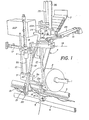
- FIG. 1 shows some parts of the spinning machine which are needed for an understanding of the invention.
- stirrup 1 providing swinging support for the bobbin 2
- shaft 3 driving said bobbin
- shaft 4 drawing the yarn and its pressing roller 5
- the up-and-down sliding means 6 intended to produce constant winding from one edge to the other of the bobbin.
- a tube loader 7 associated with a storage point forms part of the tube feeding system which accompanies the actual removal device itself.
- the removal device essentially consists of four parts.
- a first part comprises a rod 8a of a jack 8 which ends in a swingable lever means 9, which comprises a rectangular space 9a (Fig. 9) intended to lodge one of the arms of the stirrup 1, as we shall explain later on.
- This lever means 9 is, furthermore, solidly fixed to a rod 10 parallel to the rod 8a and fixed elsewhere to one of the arms of a swivelling link 11, which is fitted so as to be able to swing around the rod 8a; the other arm of said swivelling link 11 is solidly fixed to the rod of a drive jack 12 in such a way that the lever means 9 can rotate around the lengthwise axis of the rod 8a when driven by the jack 12.
- the second part of the device is intended to carry out two functions successively and comprises an arm 13 articulated around an axis 14 and driven by a jack 15.
- the free end of said arm 13 has a branch 13a at a right angle, which bears a pair of free-turning rollers 16, an articulated suction pipe 17, which will be described later on in detail, and also a cutting mechanism, which is not visible in the figures but will also be reviewed in detail.
- suction pipe 17 is connected to a source of aspiration ASP through the hollow arm 13 and 13a and that the length of the branch 13a has been chosen so that it can pass between the arms of the stirrup 1 when the arm 13 swings according to the drive of the jack 15.
- the third part of the device is intended to create a reserve of yarn at one end of the winding tube.
- This part therefore, is optional because it does not take a direct part in the removal operation.
- It comprises an arm 18 articulated around the same axis 14 as the arm 13; said arm 18 ends in a hook 19 articulated around an axle 20 and activated by an arm 21 solidly fixed to a jack 22.
- the arm 18 too is solidly fixed to a jack 23, which is intended to make said arm pivot around the axis 14.
- the fourth part of the device consists of a tube transfer means 24; said means comprises a rod 25a driven by a jack 25.
- This means 24 is in the form of a gripping means of which one of the jaws 24a is equipped with elastic return means 27.
- the means 24 is solidly fixed to a retaining means 26 intended to retain the tubes in the storage point 7 when the jack 25 makes said means 24 descend.
- Figures 3 and 4 show in greater detail and on a larger scale the various means fixed to the free end of the arms 13.
- the sleeve 28 is solidly connected to a pin 32 articulated together with the rod of a jack 33 in such a way that the pipe 17 can pivot around the bush 29.
- the inside of the box 30 comprises a cutting device which includes a pair of shears 34 and 35, of which one 34 is fixed, while the other 35 is connected to a shaft 36 by means of a connecting means 37, on which said shears 35 is articulated about a crosswise axle 38.
- a spring 39 pushes the shears 35 to make it swing clockwise (Fig. 3) about the axle 38.
- the shaft 36 is connected to the rod of a jack 40 by a pin 41.
- the hole is freely open so as to permit a free passage for the yarn through said hole and therefrom in the direction of the branch 13a through the duct 31 a in the connecting piece 31.
- a double ramp 42 and a conveyor belt 43 serve to withdraw the full bobbins.
- Figure 1 shows the starting position of various parts of the removal device at the moment when the device is brought in front of the spinning station at which it is necessary to remove the bobbin 2.
- the device described has been envisaged as serving a plurality of spinning stations.
- the device is brought to the position shown diagrammatically by Fig. 5, that is to say, the jack 8 has swung by a quarter of a turn under the action of the jack 12 so as to put the lever means 9 in contact with one extended arm of the stirrup 1.
- Said extended arm of the stirrup 1 is ready to carry out manual removal; it is elastic in such a way that it can be separated from the opposite arm of the stirrup so as to release the bobbin.
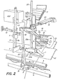
- Fig. 2 gives us a better view of certain details than the diagrammatic views and, in particular, of the positioning of the yarn and the part played by the hook 19.
- the lever means 9 first pivots slightly counterclockwise around the rod 8a of the jack 8, owing to the drive of the jack 12. The purpose of this pivoting is to shift the extended arm of the stirrup away so as to release the bobbin 2.
- the arm 13 carries out a swinging movement towards the machine; its rollers 16 come into contact with the bobbin 2, remove the latter from the stirrup 1 and push it onto the double ramp 42 until the bobbin has passed over the ridge formed at the junction of the two ramps 42, after which the bobbin rolls freely onto the conveyor belt 43.
- This organ grips with its movable jaw 24a a tube to be wound.
- the swingable lever means 9 swings slightly in a clockwise direction, just to enable the arms of the stirrup 1 to grip the tube between them, in the meantime keeping the stirrup raised.
- FIG. 7 shows the next phase, during which the rod 8a lowers the stirrup 1 with the help of the lever 9.
- the tube to be wound meets the strand of yarn stretched between the aspiration pipe and the hook 19 and pulls it so as to grip it against the drive shaft 3.
- the edge of the tube to be wound which presses the yarn against the drive shaft has some retaining means, such as some small rough areas or a tacky area or other like known means, for instance, so that the yarn coils around said tube but only towards the edge thereof, on an area of the tube outside the normal zone on which the sliding means 6 causes the winding to sweep up and down.
- the portion of yarn thus wound serves to form a reserve intended to enable users to connect together the end of a bobbin used and the beginning of the next bobbin; in this way there is no need to stop the machine when the bobbin is changed.
- the sliding means 6 engages the yarn in its guide slot and begins to sweep up and down with the yarn so as to form a new bobbin.
- the arm 13 is brought backwards again by passing above the tube, which is still almost empty.
- the transfer means 24 is brought opposite the storage point 7.
- the jaw 24a is long enough for its free edge to meet the lower end of the feeding ramp of storage point 7, so that when said jaw 24a goes upwards again it is opened against the pressure of the return spring 27 during the end of the run of the rod 25a of the jack 25 and thus enables a new winding tube to be gripped.
- the device is then ready to be shifted towards another spinning station so as to carry out another removal of a bobbin.
- the reliability of the device and of its working is the outcome of said simplicity and of the fact that the start of the winding of the yarn on the new winding tube is a passive function, that is to say, the yarn is not brought against the tube by mechanical means but the yarn is present when the tube comes into contact with the drive shaft in such a way that the yarn is engaged between the tube and the drive shaft, this ensuring that the start of winding will be successful.
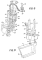
- Fig. 8 refers essentially to the second part of the device, which comprises an arm 44 articulated about the same axis 14 as the arm 13 of Figs. 1 and 2; the drive jack of this part has not been shown because it is like the jack 15 shown in said Figures.
- the free end of the arm 44 also has a branch 44a at a right angle, which bears a free roller 45.
- a support 46 is fitted so as to swing on the arm 44 through a pivot 47, and a guide pin 48 is engaged in an opening 49 shaped like an arc of a circle in the support 46.
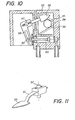
- the free end of the pipe 50 ends in a box 53 which has an opening 54 in its lower face (Fig. 10).
- Said box 53 contains a cutting device that comprises two fixed blades 55 lying at a tangent to the edge of the opening 54 and one shearing blade 56 with two shearing edges, fitted so as to swivel about a shaft 57.
- An arm 58 solidly fixed to said shearing blade 56 is in contact with the piston 59 of a drive jack 60.
- the shearing blade 56 lies at the end of a springy strip 61 which serves to press the shearing blade 56 against the fixed blades 55.
- the box 53 is solidly fixed to the end of a piston rod 62 of a jack 63.
- the rigid pipe 50 is connected to a rail 64 having two rollers 65 fixed at one end of an arm 66, of which the other end is solidly fixed to the pipe 50.
- the rail 64 comprises a vertical part and also a sloped part that is intended to make the support 46 swing clockwise when the piston 62 makes the pipe 50 go downwards to aspirate the production yarn and to perform in this way the same function as the swinging pipe 17 of Figs. 1 and 2.
- a valve 67 operated by a jack 68 lies on the hose 51 and serves to interrupt aspiration for the purpose which we shall explain later.
- the yarn is then sucked into the pipe 50, and the piston 62 is brought back to the position drawn with continuous lines and pulls with it the pipe 50 and the yarn sucked thereinto.
- the arm 44 then swings into the position of the arm 13 shown in Fig. 2 so as to discharge the bobbin, with help from the roller 45 to pull the yarn sucked in by the pipe 50.
- the shearing blade 56 (Fig. 10) is moved by the jack 60 and comes into a symmetrical position in relation to the opening 54.
- the yarn is cut between the shearing blade 56 and the fixed blade 55, and the bobbin is thus separate from the pipe 50.
- the end of the yarn connected to the box continues to be aspirated during the operations which follow and which are the same as those described earlier for the lay-out detailed in Figs. 1 to 7 inclusive up to the time of the re-starting of the winding of the yarn.
- the double-edged shearing blade 56 swings back and shears again the yarn so as to free it and enable it to coil around the new bobbin.
- the jack 68 closes the valve 67 and this stops the suction so as to facilitate release of the yarn.
- Fig. 9 refers to the first part of the device serving to activate the stirrup 1.
- This Figure shows the jack 8, its rods 8a, the holding element 9 with its release end 9a, the rod 10 and the swivelling element 11 with its two arms and with its drive jack 12.
- the lever means 9 has to be able to take up positions at three different angles around the lengthwise axis of the rod 8a.
- a positioning jack 69 is fixed to the two-branch swivelling link 11 in a position parallel to the lengthwise axis of the rod 8a.
- a positioning release 70 is arranged on a fixed part of the framework B of the device wherein the swivelling link 11 pivots.
- Two limit switches 71 and 71 a are arranged on the rod of the jack 69.
- the release means 70 is arranged opposite the rod of the jack 69 when the lever 9 is in the position wherein the release means 9a lodges the arm of the stirrup 1 so as to raise it.
- Said limit switch serves to govern the feed for the jack 12 so as to halt the run thereof.
Landscapes
- Engineering & Computer Science (AREA)
- Textile Engineering (AREA)
- Spinning Or Twisting Of Yarns (AREA)
- Replacing, Conveying, And Pick-Finding For Filamentary Materials (AREA)
Priority Applications (1)
| Application Number | Priority Date | Filing Date | Title |
|---|---|---|---|
| AT80830019T ATE6416T1 (de) | 1979-04-05 | 1980-03-29 | Spulenwechselvorrichtung fuer eine offen-endspinnmaschine. |
Applications Claiming Priority (2)
| Application Number | Priority Date | Filing Date | Title |
|---|---|---|---|
| CH317879A CH627500A5 (fr) | 1979-04-05 | 1979-04-05 | Dispositif de levee de bobines pour un metier a filer open-end. |
| CH3178/79 | 1979-04-05 |
Publications (2)
| Publication Number | Publication Date |
|---|---|
| EP0017631A1 EP0017631A1 (en) | 1980-10-15 |
| EP0017631B1 true EP0017631B1 (en) | 1984-02-29 |
Family
ID=4250306
Family Applications (1)
| Application Number | Title | Priority Date | Filing Date |
|---|---|---|---|
| EP80830019A Expired EP0017631B1 (en) | 1979-04-05 | 1980-03-29 | Device to remove bobbins for an open-end spinning machine |
Country Status (8)
| Country | Link |
|---|---|
| US (1) | US4335859A (enExample) |
| EP (1) | EP0017631B1 (enExample) |
| JP (1) | JPS55140463A (enExample) |
| AT (1) | ATE6416T1 (enExample) |
| CH (1) | CH627500A5 (enExample) |
| CS (1) | CS264255B2 (enExample) |
| DE (1) | DE3066731D1 (enExample) |
| IT (1) | IT1154719B (enExample) |
Cited By (1)
| Publication number | Priority date | Publication date | Assignee | Title |
|---|---|---|---|---|
| CN107587220A (zh) * | 2016-07-08 | 2018-01-16 | 塞维欧纺织机械股份公司 | 自由端纺纱机器中的落纱方法 |
Families Citing this family (16)
| Publication number | Priority date | Publication date | Assignee | Title |
|---|---|---|---|---|
| US4496109A (en) * | 1981-04-28 | 1985-01-29 | Celanese Corporation | Apparatus for cutting, aspirating and rethreading a traveling filamentary yarn |
| US4441660A (en) * | 1982-05-27 | 1984-04-10 | E. I. Du Pont De Nemours And Company | Apparatus for automatically doffing yarn packages and donning empty bobbins on a winder |
| JPS5992873A (ja) * | 1982-11-20 | 1984-05-29 | Teijin Seiki Co Ltd | 巻取機械からのパツケ−ジ玉揚げ方法および装置 |
| JPS6056780A (ja) * | 1983-09-07 | 1985-04-02 | Murata Mach Ltd | ワインダにおける空ボビン供給システム |
| JPS60139834A (ja) * | 1983-12-26 | 1985-07-24 | Teijin Seiki Co Ltd | 巻取機械からのパッケ−ジ玉揚げ方法および装置 |
| US4550880A (en) * | 1984-04-06 | 1985-11-05 | Belmont Textile Machinery Company | Method and apparatus for detecting the position of a take-up package during an automatic doffing and donning cycle |
| US4591105A (en) * | 1984-04-06 | 1986-05-27 | Belmont Textile Machinery Company | Method and apparatus for automatically doffing and donning take-up packages on a winder |
| USRE33111E (en) * | 1984-04-06 | 1989-11-14 | Belmont Textile Machinery Company | Method and apparatus for automatically doffing and donning take-up packages on a winder |
| IT1202589B (it) * | 1987-02-27 | 1989-02-09 | Savio Spa | Dispositivo e procedimento per la levata autromatica delle rocche in una macchina roccatrice |
| CS268034B1 (en) * | 1987-09-24 | 1990-03-14 | Burysek Frantisek | Mobile device for wound-up bobbins change |
| US6484961B2 (en) * | 1999-12-29 | 2002-11-26 | Superba | Machine for tucking, labelling and palletizing spools at the outlet of a winder or any other machine producing spools of thread and process practiced by this machine |
| DE102012005374B4 (de) * | 2012-03-16 | 2023-09-28 | Maschinenfabrik Niehoff Gmbh & Co Kg | Spulenwechselvorrichtung |
| CN108313827B (zh) * | 2018-03-29 | 2024-06-14 | 南京宏跃新能技术有限公司 | 一种纺丝用纸管转运装置 |
| CN108657803B (zh) * | 2018-07-02 | 2023-12-12 | 浙江凯成智能设备股份有限公司 | 一种喇叭管自动下管及送入总成 |
| CN109665356B (zh) * | 2018-12-20 | 2023-12-05 | 浙江钜业机械设备有限公司 | 带自动上料功能的胶带复卷设备 |
| CN112125052A (zh) * | 2020-09-29 | 2020-12-25 | 王平堂 | 一种低压线缆收卷装置 |
Family Cites Families (14)
| Publication number | Priority date | Publication date | Assignee | Title |
|---|---|---|---|---|
| FR1166402A (fr) * | 1950-11-07 | 1958-11-12 | Algemene Kunstzijde Unie Nv | Dispositif pour sectionner des fils, filés, cordes et produits similaires en mouvement |
| GB1174441A (en) * | 1966-04-08 | 1969-12-17 | Murata Machinery Ltd | Automatic Yarn Winding Machines. |
| FR1484249A (fr) * | 1966-06-21 | 1967-06-09 | Fiber Industries Inc | Appareil de transfert et d'enfilage pour machines textiles |
| US3820730A (en) * | 1968-12-24 | 1974-06-28 | T Endo | Automatic doffing apparatus for textile machine having one or more winding units |
| FR2096768B1 (enExample) * | 1970-06-01 | 1974-06-21 | Daiwa Spinning Co Ltd | |
| CS167565B1 (enExample) * | 1972-09-25 | 1976-04-29 | ||
| GB1474571A (en) * | 1973-04-16 | 1977-05-25 | Daiwa Spinning Co Ltd | Handling yarn ends during doffing and donning in a yarn winder |
| US3940077A (en) * | 1973-08-06 | 1976-02-24 | Murata Kikai Kabushiki Kaisha | Apparatus for and a method of yarn doffing |
| JPS5040838A (enExample) * | 1973-08-14 | 1975-04-14 | ||
| DE2506362C2 (de) * | 1975-02-14 | 1992-01-02 | Stahlecker, Fritz, 7347 Bad Überkingen | Offenend-Spinnmaschine |
| CH596343A5 (enExample) * | 1976-01-08 | 1978-03-15 | Nuova San Giorgio Spa | |
| DE2620428A1 (de) * | 1976-05-08 | 1977-11-24 | Fritz Stahlecker | Offenend-spinnmaschine mit einer verfahrbaren vorrichtung zum entnehmen von vollen spulen und zum einsetzen von zu bespulenden huelsen |
| DE2624499A1 (de) * | 1976-06-01 | 1977-12-15 | Fritz Stahlecker | Offenend-spinnmaschine mit einer vorrichtung zum auswechseln von vollen spulen gegen leerhuelsen |
| DE2828868A1 (de) * | 1977-06-30 | 1979-01-18 | Ishikawa Seisakusho Kk | Verfahren und vorrichtung zum automatischen entladen und laden einer garnverarbeitungsmaschine |
-
1979
- 1979-04-05 CH CH317879A patent/CH627500A5/fr not_active IP Right Cessation
-
1980
- 1980-03-28 CS CS802174A patent/CS264255B2/cs unknown
- 1980-03-29 AT AT80830019T patent/ATE6416T1/de not_active IP Right Cessation
- 1980-03-29 DE DE8080830019T patent/DE3066731D1/de not_active Expired
- 1980-03-29 EP EP80830019A patent/EP0017631B1/en not_active Expired
- 1980-04-01 IT IT8083344A patent/IT1154719B/it active
- 1980-04-03 US US06/137,291 patent/US4335859A/en not_active Expired - Lifetime
- 1980-04-05 JP JP4408880A patent/JPS55140463A/ja active Granted
Cited By (2)
| Publication number | Priority date | Publication date | Assignee | Title |
|---|---|---|---|---|
| CN107587220A (zh) * | 2016-07-08 | 2018-01-16 | 塞维欧纺织机械股份公司 | 自由端纺纱机器中的落纱方法 |
| CN107587220B (zh) * | 2016-07-08 | 2022-04-19 | 塞维欧纺织机械股份公司 | 自由端纺纱机器中的落纱方法 |
Also Published As
| Publication number | Publication date |
|---|---|
| JPH0250217B2 (enExample) | 1990-11-01 |
| CS217480A2 (en) | 1988-09-16 |
| IT8083344A0 (it) | 1980-04-01 |
| EP0017631A1 (en) | 1980-10-15 |
| DE3066731D1 (en) | 1984-04-05 |
| ATE6416T1 (de) | 1984-03-15 |
| JPS55140463A (en) | 1980-11-01 |
| IT1154719B (it) | 1987-01-21 |
| CS264255B2 (en) | 1989-06-13 |
| CH627500A5 (fr) | 1982-01-15 |
| US4335859A (en) | 1982-06-22 |
Similar Documents
| Publication | Publication Date | Title |
|---|---|---|
| EP0017631B1 (en) | Device to remove bobbins for an open-end spinning machine | |
| US5016829A (en) | Takeup machine | |
| EP0087783B1 (en) | Method and apparatus for winding strands of glass fibers | |
| US4083171A (en) | Method and apparatus for eliminating an abnormality in a thread to be wound onto the bobbin of an open-end spinning device | |
| EP0733576A2 (en) | High speed dual head on-line winding apparatus | |
| JPS6114064B2 (enExample) | ||
| US4630782A (en) | Method and apparatus for forming a thread reserve from the thread end of a textile coil | |
| DE2501735A1 (de) | Verfahren und vorrichtung zur automatisierung des auflaufspulenwechsels an einer spinnmaschine, insbesondere rotor- spinnmaschine | |
| US4591105A (en) | Method and apparatus for automatically doffing and donning take-up packages on a winder | |
| GB2100300A (en) | Method and device for winding a newly joined thread onto a tube newly inserted into a winding device | |
| US4541235A (en) | Method and device for starting the operation of a friction-spinning unit | |
| US5083716A (en) | Device and method for automatically doffing bobbins in a winding machine | |
| JPS61140474A (ja) | 巻管内へボビンの糸端部を挿入する装置 | |
| US3136494A (en) | Method and means for preparing spinning cops for rewinding | |
| EP0805118B1 (de) | Spulstelle einer Kreuzspulen herstellenden Textilmaschine | |
| GB2047290A (en) | Apparatus for forming a reserve winding on a bobbin | |
| US4352466A (en) | Device for making a thread reserve | |
| US5020736A (en) | Device for connecting strips of material | |
| US4295330A (en) | Re-attachment device for an open-end type spinning frame | |
| US5318232A (en) | Method and apparatus for transferring a thread from a full package to an empty tube | |
| US3043529A (en) | Apparatus for preparing coils of yarn for further fabrication | |
| US3475891A (en) | Method of and apparatus for doffing yarns in the centrifugal pot spinning process | |
| US4165046A (en) | Doffing apparatus in spinning machine | |
| US6115904A (en) | Rotatable dewiring apparatus and method | |
| US4248037A (en) | Yarn positioning means for open-end spinning machine piecing apparatus |
Legal Events
| Date | Code | Title | Description |
|---|---|---|---|
| PUAI | Public reference made under article 153(3) epc to a published international application that has entered the european phase |
Free format text: ORIGINAL CODE: 0009012 |
|
| AK | Designated contracting states |
Designated state(s): AT BE CH DE FR GB LU NL SE |
|
| 17P | Request for examination filed |
Effective date: 19801205 |
|
| GRAA | (expected) grant |
Free format text: ORIGINAL CODE: 0009210 |
|
| AK | Designated contracting states |
Designated state(s): AT BE CH DE FR GB LI LU NL SE |
|
| PG25 | Lapsed in a contracting state [announced via postgrant information from national office to epo] |
Ref country code: SE Effective date: 19840229 Ref country code: NL Effective date: 19840229 Ref country code: BE Effective date: 19840229 Ref country code: AT Effective date: 19840229 |
|
| REF | Corresponds to: |
Ref document number: 6416 Country of ref document: AT Date of ref document: 19840315 Kind code of ref document: T |
|
| PG25 | Lapsed in a contracting state [announced via postgrant information from national office to epo] |
Ref country code: LU Free format text: LAPSE BECAUSE OF NON-PAYMENT OF DUE FEES Effective date: 19840331 |
|
| REF | Corresponds to: |
Ref document number: 3066731 Country of ref document: DE Date of ref document: 19840405 |
|
| ET | Fr: translation filed | ||
| NLV1 | Nl: lapsed or annulled due to failure to fulfill the requirements of art. 29p and 29m of the patents act | ||
| PLBE | No opposition filed within time limit |
Free format text: ORIGINAL CODE: 0009261 |
|
| STAA | Information on the status of an ep patent application or granted ep patent |
Free format text: STATUS: NO OPPOSITION FILED WITHIN TIME LIMIT |
|
| 26N | No opposition filed | ||
| REG | Reference to a national code |
Ref country code: CH Ref legal event code: PUE Owner name: SAVIO S.P.A. |
|
| REG | Reference to a national code |
Ref country code: FR Ref legal event code: CD |
|
| PGFP | Annual fee paid to national office [announced via postgrant information from national office to epo] |
Ref country code: FR Payment date: 19910222 Year of fee payment: 12 |
|
| PGFP | Annual fee paid to national office [announced via postgrant information from national office to epo] |
Ref country code: CH Payment date: 19910308 Year of fee payment: 12 |
|
| PGFP | Annual fee paid to national office [announced via postgrant information from national office to epo] |
Ref country code: GB Payment date: 19910322 Year of fee payment: 12 |
|
| PGFP | Annual fee paid to national office [announced via postgrant information from national office to epo] |
Ref country code: DE Payment date: 19910323 Year of fee payment: 12 |
|
| PG25 | Lapsed in a contracting state [announced via postgrant information from national office to epo] |
Ref country code: GB Effective date: 19920329 |
|
| PG25 | Lapsed in a contracting state [announced via postgrant information from national office to epo] |
Ref country code: CH Effective date: 19920331 |
|
| REG | Reference to a national code |
Ref country code: GB Ref legal event code: 732 |
|
| GBPC | Gb: european patent ceased through non-payment of renewal fee | ||
| PG25 | Lapsed in a contracting state [announced via postgrant information from national office to epo] |
Ref country code: FR Effective date: 19921130 |
|
| REG | Reference to a national code |
Ref country code: CH Ref legal event code: PL |
|
| PG25 | Lapsed in a contracting state [announced via postgrant information from national office to epo] |
Ref country code: DE Effective date: 19921201 |
|
| REG | Reference to a national code |
Ref country code: FR Ref legal event code: ST |