EP0017228A1 - Dispositif de mémoire - Google Patents
Dispositif de mémoire Download PDFInfo
- Publication number
- EP0017228A1 EP0017228A1 EP80101776A EP80101776A EP0017228A1 EP 0017228 A1 EP0017228 A1 EP 0017228A1 EP 80101776 A EP80101776 A EP 80101776A EP 80101776 A EP80101776 A EP 80101776A EP 0017228 A1 EP0017228 A1 EP 0017228A1
- Authority
- EP
- European Patent Office
- Prior art keywords
- strobe signal
- junction point
- column
- row
- response
- Prior art date
- Legal status (The legal status is an assumption and is not a legal conclusion. Google has not performed a legal analysis and makes no representation as to the accuracy of the status listed.)
- Granted
Links
Images


Classifications
-
- G—PHYSICS
- G11—INFORMATION STORAGE
- G11C—STATIC STORES
- G11C11/00—Digital stores characterised by the use of particular electric or magnetic storage elements; Storage elements therefor
- G11C11/21—Digital stores characterised by the use of particular electric or magnetic storage elements; Storage elements therefor using electric elements
- G11C11/34—Digital stores characterised by the use of particular electric or magnetic storage elements; Storage elements therefor using electric elements using semiconductor devices
- G11C11/40—Digital stores characterised by the use of particular electric or magnetic storage elements; Storage elements therefor using electric elements using semiconductor devices using transistors
- G11C11/401—Digital stores characterised by the use of particular electric or magnetic storage elements; Storage elements therefor using electric elements using semiconductor devices using transistors forming cells needing refreshing or charge regeneration, i.e. dynamic cells
- G11C11/4063—Auxiliary circuits, e.g. for addressing, decoding, driving, writing, sensing or timing
- G11C11/407—Auxiliary circuits, e.g. for addressing, decoding, driving, writing, sensing or timing for memory cells of the field-effect type
-
- G—PHYSICS
- G11—INFORMATION STORAGE
- G11C—STATIC STORES
- G11C8/00—Arrangements for selecting an address in a digital store
- G11C8/16—Multiple access memory array, e.g. addressing one storage element via at least two independent addressing line groups
Definitions
- CAS After completion of latching of address inputs in response to RAS, CAS becomes active by being turned from a high level to a low level thereby to incorporate the input levels at the address terminals at this time in the memory as column address inputs.
- WRITE ENABLE abbreviated as WE
- WE WRITE ENABLE
- the present invention relates to a memory circuit constituted of semiconductor elements, and more particularly to a memory circuit employing insulated gate field effect transistors (IGFET's) fabricated on a semixonductor chip.
- IGFET's insulated gate field effect transistors
- dynamic RAM dynamic random access memories employing IGFETs
- dynamic RAM dynamic random access memories
- a 2-clock multi-address system has been employed in a 16 K-bit memory as well as in a 64 K-bit memory both with a 16-pin package structure.
- the details of this multi-address system is disclosed in the specification and drawings of U.S. Patent 3, 969, 706 issued to Robert J. Proebsting et al on July 13, 1976.
- two input clocks that is, a row strobe signal defined as ROW ADDRESS STROBE (abbreviated as RAS) and a column strobe signal defined as COLUMN ADDRESS STROBE (abbreviated as CAS) are generated in a predetermined sequence.
- RAS row strobe signal
- COLUMN ADDRESS STROBE abbreviated as CAS
- Another object of the present invention is to provide a practical and useful circuit structure for realizing the aforementioned feature.
- a memory circuit characterized by the following function:
- a semiconductor integrated circuit for achieving the above-featured memory circuit which comprises a load element having one end coupled to a first power supply terminal and the other end coupled to a first junction point, a first IGFET having drain coupled to the first junction point, gate receiving CAS and source coupled to a second power supply terminal, a second IGFET having drain coupled to the first junction point, gate coupled to a second junction point and source coupled to the second power supply terminal, a third IGFET having drain coupled to the first power supply terminal, gate receiving a first clock which takes its active level in response to RAS input going into an inactive period and then inactive within the same inactive period and source coupled to the second junction point, and a fourth IGFET having drain coupled to the second junction point, gate receiving CAS and source coupled to the second power supply terminal.
- MOST MOS transistors
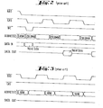
- Fig. 1 (A) and Fig. 1 (B) Timing relations between RAS, CAS, WE, data input and address input in a read cycle and in a write cycle are illustrated in Fig. 1 (A) and Fig. 1 (B) together with a general waveform of the data output.
- the read cycle of Fig. 1 (A) after a necessary access time has elapsed from a change of CAS to a low level, the effective data appear at the data output and are maintained until CAS is changed to a high level to be reset.
- the write cycle of Fig. 1 (B) it is a general output mode that the data output terminal is kept at a high impedance state (Hi-Z) and there appear no data.
- page mode RAS and CAS are changed to a low level to be enabled or activated in sequence, and reset state and enabled state of CAS are repeated while maintaining RAS at a low level.
- write-in or read-out can be achieved in the memory cell at the column address designated by the address input in response to CAS only.
- this operation is called "page mode”.
- the page mode operation and the RAS ONLY REFRESH operation form the characteristic operation of the RAM of 2-clock multi-address system, and still further, an operation illustrated in Fig. 4 has been employed recently.
- the RAM shown in Fig. 5 comprises a row address inverter 50, row decoders 51 and 52, a column address inverter 53, memory cell arrays 54 and 57, column decoders 55 and 56, a sense amplifier 55', an output amplifier 58, a latch control circuit 59 and a control timing generator circuit 60 responsive to RAS and CAS.
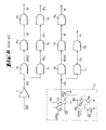
- the structure of the control tirning generator circuit 60 is disclosed in Fig. 6.
- the respective timing signal waveforms generated via inverters I 1 to I 4 and buffers B 1 to B9 in Fig. 6 are shown in Fig. 7.
- a level-inverted output RAS derived from the inverter I 1 rises at first.
- precharge timing signals XP 0 , XP and XP 2 are successively changed to the low level.
- a timing signal AERAS rises, so that the output of the row address inverter 50 can respond to the address input.
- a timing signal RA rises, and hence the selected word line rises in level.
- a timing signal SE rises, so that the sense amplifier 55' is enabled.
- the contents in the memory cells 54 and 57 on the selected word line are refreshed.
- circuit operations in response to RAS have been finished.
- a gate of MOST Q 52 forming the load of the inverter 1 3 to which CAS is applied is charged in response to AERAS derived from RAS. If this charging has been completed and also CAS shifts from the high level to the low level to achieve its active state, then a level-inverted output CAS rises.
- precharging timing signals YP 0 and YP 1 fall in level and a timing signal AECAS rises, so that the output of the column address inverter 53 responds to the address input.
- a timing signal RE rises and hence the digit line of the selected column is connected to a data input/output line.
- a timing signal DE rises in level, so that the output amplifier 58 is enabled, hence the information in the selected memory cell that has appeared on the data input/output lines DB and DB is amplified. Thus the necessary data are provided at a data output terminal DATA OUT. Then, circuit operations in response to CAS have been finished.
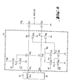
- MOST Q 81 becomes non-conducting and MOST Q 82 becomes conducting, so that a junction point N 13 shifts to the ground potential and hence MOSTs Q 83 and Q 84 become non-conducting.
- junction points N 11 and N 12 remains a read-out information level, which is dynamically maintained by their capacitance, and junction points N 14 and N 15 are reset to the ground potential on the side of the output amplifier 58.
- MOSTs Q 85 to Q 90 form a control circuit for maintaining the output terminal DATA CUT at a high impedance when CAS is at the high level. In this case, CAS is held at the low level and MOST Q 86 is non-conducting.
- junction point N 16 stores an electric charge passed through MOST Q 85 in responce to the high level of RE, and thus the junction point N 16 is held at the high level.
- MOST Q 88 is chosen to have a sufficiently large current capacity with respect to MOST Q 87 so that a junction point N 17 may be held at the low level, and MOST Q 89 and MOST Q 90 are non-conducting, resulting in no influence upon the levels at the junction points N 11 and N 12 .
- the present invention is characterized in that where RAS is subsequently made its active level while CAS is kept at its inactive level, the RAS system circuit can operate but the CAS system circuit is kept reset and does not operate. More particularly, although the timing signal CAS derived by inverting the level of CAS can be reset when RAS is reset while maintaining CAS active, upon subsequent activation of RAS the rise of the timing signal CAS is suppressed, so that CAS system circuit does not change from the reset state at this time, and all the activation operations therein are inhibited.
- Fig. 9 The waveforms of the respective timing signals according to the present invention are illustrated in Fig. 9 in a similar fashion to Fig. 7.
- the timing signals RAS, AERAS, RA, SE, SP O , XP 1 , XP 2 generated in the RAS system timing generator circuit are the same as those in Fig. 7, and the RAS system timing generator circuit (see Fig. 11) is also identical to that shown in Fig. 6.
- the CAS system timing signals are modified according to the present invention, and they are represented by reference letters CAS', AECAS', RE', DE', YD 0 ' and YP 1 '.
- the CAS system timing generator circuit is accordingly modified as shown in Fig. 11. Since the restriction imposed on the WE input in the prior art system shown in Fig. 4 is eliminated, HIDDEN REFRESH in the circuit system according the the present invention is effected to irrespective of WE as shown in Fig. 10. Furthermore, the circuit system according to the present invention involves an additional advantage that since the activation operations. in the CAS system circuit are entirely suppressed, the power consumption upon HIDDEN REFRESH can be made as small as that upon RAS ONLY REFRESH illustrated in Fig. 3.
- Fig. 11 shows a basic circuit construction of the timing generator circuit
- Fig. 12 which illustrates waveforms at principal junction points.
- the activation timing signal CAS' derived by level-inversion of the CAS input is normally generated by an inverter I 3 ' including MOST s Q 71' Q 72 and Q 73 .
- CAS is turned to the active (low) level to turn MOST Q 73 to non-conducting, and CAS' begins to rise ghrough MOST Q 72 , which is driven to an unsaturated region owing to the existence of a boot-strap capacitor Cl F, and hence CAS' reaches the VD D level.
- the activation period of RAS terminates and it goes into a reset period
- the clock XP 00 MOST Q 74 rises immediately, and after a junction point 73 3 has been sufficiently charged through MOST Q 74 it shifts to the low level within the reset period of RAS. Due to the rise of the junction point 73, MOST Q 76 becomes conducting and CAS' shifts to the ground potential.
- MOST Q 75 is non-conducting, so that the junction point 73 is held at the high level, and after XP 00 becomes low, the junction point 73 is maintained at the high level by a capacitance at the junction point 73. Subsequently, when RAS is made at its active (low) level again while CAS is kept at the low level, the timing signal AERAS rises and thereby the junction point 71 is charged. However, if the current capacity of MOST Q 76 is chosen sufficiently large with respect to that of MOST Q 72 , then CAS' cannot rise because the junction point 73 is kept at the high level.
- XP 0 may similarly be used.
- the circuit of MOSTs Q 74 to Q 76 can realize the timing condition in Fig. 9 and the operation mode illustrated in Fig. 10, and it can be proved by reference to Fig. 13 that this circuit does not affect any other timing condition of CAS during the period from the reset of RAS to the next activation of the same.
- the output circuit has such construction as shown in Fig. 8 that in the read cycle, after completion of an access operation, effective data can be maintained at the output terminal so long as CAS is not reset.
- RAS is made at the active level at first, then RAS rises up to the V DD level via MOST Q 2 owing to the boot-strap capacitor CIF.
- a junction point 3 rises up to the level of (V DD - threshold voltage), and so, by selecting a current capacity of MOST Q 8 sufficiently large with respect to that of MOST Q 7 , XP 0 is shifted from the V DD level to the low level.
- a timing signal AERAS rises up to the V DD level, and thereafter activation operations in the RAS series circuit are carried out.
- a junction point 15 is raised via MOST Q 26 up to the level of (V DD - threshold voltage), and as waiting for the later one of CAS being activated and a junction point 18 which is an output of a delay circuit responsive to AERAS shifting to the fround potential, that is; after MOSTs Q 73 and Q 54 both have become non-conducting, CAS rises. Then CAS reaches the V DD level via MOST Q 72 owing to a boot-strap capacitor Cl F . In response to CAS, activation operations in the CAS system circuit are effected, and assuming that the cycle under consideration is a read cycle, effective data appear at the output terminal.
- a circuitry consisting of MOSTs Q 20 to Q 25 operates, and as a result, when a junction point 14 rises, MOST Q 17 and Q 19 becomes conducting, resulting in shift of XP 00 to the ground potential.
- XP 00 is held at the high level equal to V DD during the operation period of the circuitry of MOSTs Q 20 to Q 25 , During this period, a junction point 19 is charged via MOST Q 35 up to the level of (VD D - threshold voltage). The voltage at the junction point 19 is indicated as V 19 in Fig. 15.
- MOST Q 74 If only MOST Q 74 were to be used, after XP 00 has shifted to the ground potential the junction point 19 would take the high level that is dynamically maintained, and if the period of this condition is long, there is a risk that the level may be attenuated. Therefore, as a back-up, MOST Q 37 having a small current capacity and having XP 0 applied to its gate is added between the VDD power source and the junction point 19. Since CAS is not reset, effective data are in themselves maintained at the output terminal.
- the activation operations in the CAS system circuit are all inhibited, and only refresh operations in response to the RAS input can be effected. So long as the CAS input is held at the low level, effective data can be maintained in themselves at the output terminal, even if reset and activation of the RAS input are repeated the circuit other than the RAS system circuit is held in a reset condition without operating at all, and thus refresh is effected in succession. As a result, HIDDEN REFRESH illustrated in Fig. 10 can be realized.
- a circuit system characterized by the function that after necessary operations for a selected memory cell have been completed by sequentially making RAS and GAS at their at active levels, RAS is reset while CAS is kept at its active levei, and after a necessary reset period, when RAS is again made the active level, all the activation operations responsive to CAS are inhibited, whereby the state at the time point when said necessary operations were completed can be in itself maintained at the data output terminal.
- the aforementioned function can be realized by adding to an inverter for generating CAS a circuit comprising a first MOST (Q 76 in Fig.
Landscapes
- Engineering & Computer Science (AREA)
- Microelectronics & Electronic Packaging (AREA)
- Computer Hardware Design (AREA)
- Dram (AREA)
Applications Claiming Priority (2)
| Application Number | Priority Date | Filing Date | Title |
|---|---|---|---|
| JP4067179A JPS55132595A (en) | 1979-04-04 | 1979-04-04 | Semiconductor circuit |
| JP40671/79 | 1979-04-04 |
Publications (2)
| Publication Number | Publication Date |
|---|---|
| EP0017228A1 true EP0017228A1 (fr) | 1980-10-15 |
| EP0017228B1 EP0017228B1 (fr) | 1984-07-11 |
Family
ID=12586981
Family Applications (1)
| Application Number | Title | Priority Date | Filing Date |
|---|---|---|---|
| EP80101776A Expired EP0017228B1 (fr) | 1979-04-04 | 1980-04-03 | Dispositif de mémoire |
Country Status (4)
| Country | Link |
|---|---|
| US (1) | US4322825A (fr) |
| EP (1) | EP0017228B1 (fr) |
| JP (1) | JPS55132595A (fr) |
| DE (1) | DE3068493D1 (fr) |
Cited By (2)
| Publication number | Priority date | Publication date | Assignee | Title |
|---|---|---|---|---|
| EP0111741A2 (fr) * | 1982-11-24 | 1984-06-27 | Siemens Aktiengesellschaft | Circuit semi-conducteur intégré avec une mémoire dynamique lecture-écriture |
| GB2162179A (en) * | 1984-07-24 | 1986-01-29 | Sandoz Ltd | Naphthyl analogs of mevalonolactone and derivatives thereof, processes for their production and their use |
Families Citing this family (16)
| Publication number | Priority date | Publication date | Assignee | Title |
|---|---|---|---|---|
| US4453237A (en) * | 1980-10-01 | 1984-06-05 | Intel Corporation | Multiple bit output dynamic random-access memory |
| US4583193A (en) * | 1982-02-22 | 1986-04-15 | International Business Machines Corp. | Integrated circuit mechanism for coupling multiple programmable logic arrays to a common bus |
| JPS60111391A (ja) * | 1983-11-21 | 1985-06-17 | Nec Corp | 半導体出力回路 |
| JPS61292292A (ja) * | 1985-06-19 | 1986-12-23 | Toshiba Corp | 半導体記憶装置 |
| US4797573A (en) * | 1984-11-21 | 1989-01-10 | Nec Corporation | Output circuit with improved timing control circuit |
| JPS61144795A (ja) * | 1984-12-17 | 1986-07-02 | Mitsubishi Electric Corp | 半導体記憶装置 |
| US4638462A (en) * | 1985-01-31 | 1987-01-20 | International Business Machines Corporation | Self-timed precharge circuit |
| JPS61227293A (ja) * | 1985-03-30 | 1986-10-09 | Toshiba Corp | 半導体記憶装置 |
| JPS62103898A (ja) * | 1985-10-31 | 1987-05-14 | Mitsubishi Electric Corp | ダイナミツクランダムアクセスメモリ装置 |
| US4792929A (en) * | 1987-03-23 | 1988-12-20 | Zenith Electronics Corporation | Data processing system with extended memory access |
| JPH0778989B2 (ja) * | 1989-06-21 | 1995-08-23 | 株式会社東芝 | 半導体メモリ装置 |
| US4998222A (en) * | 1989-12-04 | 1991-03-05 | Nec Electronics Inc. | Dynamic random access memory with internally gated RAS |
| US5663925A (en) * | 1995-12-18 | 1997-09-02 | Micron Technology, Inc. | Method and apparatus for timing control in a memory device |
| US5745914A (en) * | 1996-02-09 | 1998-04-28 | International Business Machines Corporation | Technique for converting system signals from one address configuration to a different address configuration |
| US7313047B2 (en) * | 2006-02-23 | 2007-12-25 | Hynix Semiconductor Inc. | Dynamic semiconductor memory with improved refresh mechanism |
| KR102573585B1 (ko) * | 2020-11-23 | 2023-08-31 | 주식회사 한화 | 위험 반경을 기반으로 뇌관 발파를 제어하는 장치 및 그 방법 |
Citations (10)
| Publication number | Priority date | Publication date | Assignee | Title |
|---|---|---|---|---|
| US3962686A (en) * | 1972-05-16 | 1976-06-08 | Nippon Electric Company Limited | Memory circuit |
| US3964030A (en) * | 1973-12-10 | 1976-06-15 | Bell Telephone Laboratories, Incorporated | Semiconductor memory array |
| US3969706A (en) * | 1974-10-08 | 1976-07-13 | Mostek Corporation | Dynamic random access memory misfet integrated circuit |
| US4038646A (en) * | 1976-03-12 | 1977-07-26 | Intel Corporation | Dynamic mos ram |
| US4050061A (en) * | 1976-05-03 | 1977-09-20 | Texas Instruments Incorporated | Partitioning of MOS random access memory array |
| US4072932A (en) * | 1976-08-23 | 1978-02-07 | Texas Instruments Incorporated | Clock generator for semiconductor memory |
| US4087704A (en) * | 1974-11-04 | 1978-05-02 | Intel Corporation | Sequential timing circuitry for a semiconductor memory |
| US4090096A (en) * | 1976-03-31 | 1978-05-16 | Nippon Electric Co., Ltd. | Timing signal generator circuit |
| US4104733A (en) * | 1976-08-23 | 1978-08-01 | Hitachi, Ltd. | Address selecting circuitry for semiconductor memory device |
| GB2024474A (en) * | 1978-06-26 | 1980-01-09 | Texas Instruments Inc | On-chip refresh for dynamic memory |
Family Cites Families (1)
| Publication number | Priority date | Publication date | Assignee | Title |
|---|---|---|---|---|
| US3801964A (en) * | 1972-02-24 | 1974-04-02 | Advanced Memory Sys Inc | Semiconductor memory with address decoding |
-
1979
- 1979-04-04 JP JP4067179A patent/JPS55132595A/ja active Granted
-
1980
- 1980-04-03 DE DE8080101776T patent/DE3068493D1/de not_active Expired
- 1980-04-03 EP EP80101776A patent/EP0017228B1/fr not_active Expired
- 1980-04-04 US US06/137,333 patent/US4322825A/en not_active Expired - Lifetime
Patent Citations (10)
| Publication number | Priority date | Publication date | Assignee | Title |
|---|---|---|---|---|
| US3962686A (en) * | 1972-05-16 | 1976-06-08 | Nippon Electric Company Limited | Memory circuit |
| US3964030A (en) * | 1973-12-10 | 1976-06-15 | Bell Telephone Laboratories, Incorporated | Semiconductor memory array |
| US3969706A (en) * | 1974-10-08 | 1976-07-13 | Mostek Corporation | Dynamic random access memory misfet integrated circuit |
| US4087704A (en) * | 1974-11-04 | 1978-05-02 | Intel Corporation | Sequential timing circuitry for a semiconductor memory |
| US4038646A (en) * | 1976-03-12 | 1977-07-26 | Intel Corporation | Dynamic mos ram |
| US4090096A (en) * | 1976-03-31 | 1978-05-16 | Nippon Electric Co., Ltd. | Timing signal generator circuit |
| US4050061A (en) * | 1976-05-03 | 1977-09-20 | Texas Instruments Incorporated | Partitioning of MOS random access memory array |
| US4072932A (en) * | 1976-08-23 | 1978-02-07 | Texas Instruments Incorporated | Clock generator for semiconductor memory |
| US4104733A (en) * | 1976-08-23 | 1978-08-01 | Hitachi, Ltd. | Address selecting circuitry for semiconductor memory device |
| GB2024474A (en) * | 1978-06-26 | 1980-01-09 | Texas Instruments Inc | On-chip refresh for dynamic memory |
Non-Patent Citations (6)
| Title |
|---|
| ELECTRONIC DESIGN, Vol. 27, No. 13, 21th June 1979, pages 58-64 New York US YOUNG: "64-k RAM with single supply could be the standard for future design" * Pages 60-61: paragraph "Put refresh logic on the chip"; figure 5 * * |
| ELECTRONICS, Vol. 49, No. 10, 13th May 1976, pages 81-86 New York US KUO et al.: "16K RAM built with proven process may offer high start-up reliability" * Pages 81-86, paragraph: " Using the RAM; figure 4 * & US - A - 4 050 061 (TAXAS). * |
| ELECTRONICS, Vol. 50, No. 9, 28th April 1977, pages 115-119 New York, U.S.A. COKER: "16-K RAM Eases Memory Design for Mainframes & Microcomputers" * Figure 8 * * |
| ELECTRONICS, Vol. 52, No. 4, 15th February 1979, pages 141-147 New York US FORD et al.: "64-K dynamic RAM has pin that refreshes" * Pages 142-147, paragraphs "A Refresing Idea", "System Refresh" and "Hidden Refresh"; figures 1-3, 5, 6 * * |
| THE SEMICONDUCTOR MEMORY BOOK, Intel, Wiley Editor, 1978, pages 130-138 New York US COE: "Designing with 16K Dynamic RAM's" * Pages 134-137, paragraph: "Implementing Refresh", figures 2, 6; table 1 * * |
| THE SEMICONDUCTOR MEMORY BOOK, Intel, Wiley Editor, 1978, pages 139-181 New York, U.S.A. FIELLAND: "Dynamic RAM's used with Microprocessors" * Pages 155-159: paragraph 6, "Density through Address Multiplexing" * * |
Cited By (3)
| Publication number | Priority date | Publication date | Assignee | Title |
|---|---|---|---|---|
| EP0111741A2 (fr) * | 1982-11-24 | 1984-06-27 | Siemens Aktiengesellschaft | Circuit semi-conducteur intégré avec une mémoire dynamique lecture-écriture |
| EP0111741A3 (en) * | 1982-11-24 | 1985-05-22 | Siemens Aktiengesellschaft | Integrated semiconductor circuit with a dynamic read-write memory |
| GB2162179A (en) * | 1984-07-24 | 1986-01-29 | Sandoz Ltd | Naphthyl analogs of mevalonolactone and derivatives thereof, processes for their production and their use |
Also Published As
| Publication number | Publication date |
|---|---|
| JPS55132595A (en) | 1980-10-15 |
| JPS6235194B2 (fr) | 1987-07-31 |
| US4322825A (en) | 1982-03-30 |
| DE3068493D1 (en) | 1984-08-16 |
| EP0017228B1 (fr) | 1984-07-11 |
Similar Documents
| Publication | Publication Date | Title |
|---|---|---|
| US4429375A (en) | Consecutive addressing of a semiconductor memory | |
| US4322825A (en) | Flexible hidden refresh memory circuit | |
| US5193072A (en) | Hidden refresh of a dynamic random access memory | |
| EP0019142B1 (fr) | Dispositif de mémoire à régénération interne | |
| US4581718A (en) | MOS memory | |
| KR940000148B1 (ko) | 듀얼포트 반도체 기억장치 | |
| US4813021A (en) | Semiconductor memory device with delayed precharge signals | |
| EP0165612A2 (fr) | Circuit de mémoire comprenant une pluralité de réseaux de cellules | |
| US4766572A (en) | Semiconductor memory having a bypassable data output latch | |
| US4570242A (en) | Dynamic random-access memory | |
| EP0326183B1 (fr) | Mémoire à accès aléatoire pseudo-statique | |
| EP0109069B1 (fr) | Dispositif de mémoire dynamique à semi-conducteur | |
| JPS6213758B2 (fr) | ||
| JP2000156079A (ja) | マルチバンク構造を有する半導体メモリ装置 | |
| US4873672A (en) | Dynamic random access memory capable of fast erasing of storage data | |
| US4564925A (en) | Semiconductor memory | |
| US4797573A (en) | Output circuit with improved timing control circuit | |
| EP0075942A2 (fr) | Circuit de mémoire | |
| US4682048A (en) | Output circuit with improved timing control circuit | |
| EP0062547A2 (fr) | Circuit de mémoire | |
| EP0031995B1 (fr) | Dispositif de mémoire à semi-conducteurs comprenant une matrice de cellules de mémoire statiques | |
| US4823322A (en) | Dynamic random access memory device having an improved timing arrangement | |
| EP0162234A2 (fr) | Dispositif de mémoire | |
| US6181633B1 (en) | Semiconductor device | |
| US4267464A (en) | Decoder circuit |
Legal Events
| Date | Code | Title | Description |
|---|---|---|---|
| PUAI | Public reference made under article 153(3) epc to a published international application that has entered the european phase |
Free format text: ORIGINAL CODE: 0009012 |
|
| AK | Designated contracting states |
Designated state(s): DE FR GB NL |
|
| 17P | Request for examination filed |
Effective date: 19810415 |
|
| RAP1 | Party data changed (applicant data changed or rights of an application transferred) |
Owner name: NEC CORPORATION |
|
| GRAA | (expected) grant |
Free format text: ORIGINAL CODE: 0009210 |
|
| AK | Designated contracting states |
Designated state(s): DE FR GB NL |
|
| REF | Corresponds to: |
Ref document number: 3068493 Country of ref document: DE Date of ref document: 19840816 |
|
| ET | Fr: translation filed | ||
| PLBE | No opposition filed within time limit |
Free format text: ORIGINAL CODE: 0009261 |
|
| STAA | Information on the status of an ep patent application or granted ep patent |
Free format text: STATUS: NO OPPOSITION FILED WITHIN TIME LIMIT |
|
| 26N | No opposition filed | ||
| PGFP | Annual fee paid to national office [announced via postgrant information from national office to epo] |
Ref country code: GB Payment date: 19990408 Year of fee payment: 20 |
|
| PGFP | Annual fee paid to national office [announced via postgrant information from national office to epo] |
Ref country code: FR Payment date: 19990409 Year of fee payment: 20 Ref country code: DE Payment date: 19990409 Year of fee payment: 20 |
|
| PGFP | Annual fee paid to national office [announced via postgrant information from national office to epo] |
Ref country code: NL Payment date: 19990426 Year of fee payment: 20 |
|
| PG25 | Lapsed in a contracting state [announced via postgrant information from national office to epo] |
Ref country code: GB Free format text: LAPSE BECAUSE OF EXPIRATION OF PROTECTION Effective date: 20000402 |
|
| PG25 | Lapsed in a contracting state [announced via postgrant information from national office to epo] |
Ref country code: NL Free format text: LAPSE BECAUSE OF EXPIRATION OF PROTECTION Effective date: 20000403 |
|
| REG | Reference to a national code |
Ref country code: GB Ref legal event code: PE20 Effective date: 20000402 |
|
| NLV7 | Nl: ceased due to reaching the maximum lifetime of a patent |
Effective date: 20000403 |