EP0017218A2 - Elektronisches Steuerverfahren für Brennkraftmaschinen - Google Patents
Elektronisches Steuerverfahren für Brennkraftmaschinen Download PDFInfo
- Publication number
- EP0017218A2 EP0017218A2 EP80101756A EP80101756A EP0017218A2 EP 0017218 A2 EP0017218 A2 EP 0017218A2 EP 80101756 A EP80101756 A EP 80101756A EP 80101756 A EP80101756 A EP 80101756A EP 0017218 A2 EP0017218 A2 EP 0017218A2
- Authority
- EP
- European Patent Office
- Prior art keywords
- task
- program
- tasks
- engine
- activation request
- Prior art date
- Legal status (The legal status is an assumption and is not a legal conclusion. Google has not performed a legal analysis and makes no representation as to the accuracy of the status listed.)
- Granted
Links
Images


Classifications
-
- F—MECHANICAL ENGINEERING; LIGHTING; HEATING; WEAPONS; BLASTING
- F02—COMBUSTION ENGINES; HOT-GAS OR COMBUSTION-PRODUCT ENGINE PLANTS
- F02P—IGNITION, OTHER THAN COMPRESSION IGNITION, FOR INTERNAL-COMBUSTION ENGINES; TESTING OF IGNITION TIMING IN COMPRESSION-IGNITION ENGINES
- F02P5/00—Advancing or retarding ignition; Control therefor
- F02P5/04—Advancing or retarding ignition; Control therefor automatically, as a function of the working conditions of the engine or vehicle or of the atmospheric conditions
- F02P5/145—Advancing or retarding ignition; Control therefor automatically, as a function of the working conditions of the engine or vehicle or of the atmospheric conditions using electrical means
- F02P5/15—Digital data processing
- F02P5/1502—Digital data processing using one central computing unit
-
- F—MECHANICAL ENGINEERING; LIGHTING; HEATING; WEAPONS; BLASTING
- F02—COMBUSTION ENGINES; HOT-GAS OR COMBUSTION-PRODUCT ENGINE PLANTS
- F02D—CONTROLLING COMBUSTION ENGINES
- F02D41/00—Electrical control of supply of combustible mixture or its constituents
- F02D41/24—Electrical control of supply of combustible mixture or its constituents characterised by the use of digital means
- F02D41/26—Electrical control of supply of combustible mixture or its constituents characterised by the use of digital means using computer, e.g. microprocessor
- F02D41/263—Electrical control of supply of combustible mixture or its constituents characterised by the use of digital means using computer, e.g. microprocessor the program execution being modifiable by physical parameters
-
- F—MECHANICAL ENGINEERING; LIGHTING; HEATING; WEAPONS; BLASTING
- F02—COMBUSTION ENGINES; HOT-GAS OR COMBUSTION-PRODUCT ENGINE PLANTS
- F02M—SUPPLYING COMBUSTION ENGINES IN GENERAL WITH COMBUSTIBLE MIXTURES OR CONSTITUENTS THEREOF
- F02M23/00—Apparatus for adding secondary air to fuel-air mixture
- F02M23/04—Apparatus for adding secondary air to fuel-air mixture with automatic control
-
- F—MECHANICAL ENGINEERING; LIGHTING; HEATING; WEAPONS; BLASTING
- F02—COMBUSTION ENGINES; HOT-GAS OR COMBUSTION-PRODUCT ENGINE PLANTS
- F02D—CONTROLLING COMBUSTION ENGINES
- F02D41/00—Electrical control of supply of combustible mixture or its constituents
- F02D41/0025—Controlling engines characterised by use of non-liquid fuels, pluralities of fuels, or non-fuel substances added to the combustible mixtures
- F02D41/0047—Controlling exhaust gas recirculation [EGR]
- F02D41/005—Controlling exhaust gas recirculation [EGR] according to engine operating conditions
-
- Y—GENERAL TAGGING OF NEW TECHNOLOGICAL DEVELOPMENTS; GENERAL TAGGING OF CROSS-SECTIONAL TECHNOLOGIES SPANNING OVER SEVERAL SECTIONS OF THE IPC; TECHNICAL SUBJECTS COVERED BY FORMER USPC CROSS-REFERENCE ART COLLECTIONS [XRACs] AND DIGESTS
- Y02—TECHNOLOGIES OR APPLICATIONS FOR MITIGATION OR ADAPTATION AGAINST CLIMATE CHANGE
- Y02T—CLIMATE CHANGE MITIGATION TECHNOLOGIES RELATED TO TRANSPORTATION
- Y02T10/00—Road transport of goods or passengers
- Y02T10/10—Internal combustion engine [ICE] based vehicles
- Y02T10/12—Improving ICE efficiencies
-
- Y—GENERAL TAGGING OF NEW TECHNOLOGICAL DEVELOPMENTS; GENERAL TAGGING OF CROSS-SECTIONAL TECHNOLOGIES SPANNING OVER SEVERAL SECTIONS OF THE IPC; TECHNICAL SUBJECTS COVERED BY FORMER USPC CROSS-REFERENCE ART COLLECTIONS [XRACs] AND DIGESTS
- Y02—TECHNOLOGIES OR APPLICATIONS FOR MITIGATION OR ADAPTATION AGAINST CLIMATE CHANGE
- Y02T—CLIMATE CHANGE MITIGATION TECHNOLOGIES RELATED TO TRANSPORTATION
- Y02T10/00—Road transport of goods or passengers
- Y02T10/10—Internal combustion engine [ICE] based vehicles
- Y02T10/40—Engine management systems
Definitions
- the present invention relates to a method of electronically controlling operation of an internal combustion engine and a system for carrying out the same. More particularly, the invention concerns an electronic type engine control method in which the internal combustion engine is controlled through digital processings and arithmetic operations of a central processing unit (hereinafter referred to as CPU in abridgement).
- CPU in abridgement a central processing unit
- a method and a system for controlling an internal combustion engine (hereinafter simply referred to also as the engine) through CPU in accordance with predetermined programs are disclosed in U.S. Patents Nos. 3,969,614 and 4,163,282.
- a series of programs prepared for fetching informations from various sensors for detecting engine operating conditions and setting control quantities for every function to be controlled are executed in accordance with the rotation of the engine to thereby control the operation of the engine.
- Such control programs include a fuel quatity controls-program, an ignition timing program and an engine initiation program, for example.
- the fuel quantity control program and the ignition timing control program are executed in synchronism with detection of a predetermined crank angle during revolution of the engine, whereby signals representing the fuel supply quantity as well as the ignition timing advancing angle which are arithmetically determined through execution of the programs described above are supplied to associated pulse output circuits.
- the control of the engine operation in which predetermined programs are executed in certain states of the engine operation and terminated upon setting of the arithmetically determined data at the pulse output circuit or upon changing of the operating state of the engine in the manner described above will means that the loaded state of the central control unit or CPU undergoes remarkable variations in dependence on the operating conditions of the engine to a great disadvantage.
- timer activation activation of the tasks at a constant period or timing for all the tasks
- timer activation activation of the tasks in accordance with the-respective allotted timings when the cranking operation by the actuation of a starter motor has completed. Accordingly, it is necessary to smoothly change a method of generating the task activation requests for the execution of the programs.
- an object of the invention is to provide a method of assuring a smooth transition of the task activation to the timer activation.
- Another object of the invention is to provide a control method according to which an activation request is issued before the transition to the timer activation for smoothly controlling the engine at the start thereof.
- Still another object of the invention is to provide a method of electronically controlling an internal combustion engine which assures a smooth engine control in the engine starting operation.
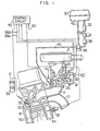
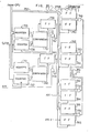
- Fig. 1 which shows in a partially sectioned view a fuel injection system for an internal combustion engine together with an electronic control system
- air is supplied to cylinders 8 (only one of which is shown in Fig. 1) from an air cleaner 2 through a throttle chamber 4 and an intake conduit or manifold 6.
- Combustion product gas is discharged to the atmosphere from the cylinder 8 through an exhaust conduit 10.
- an injector 12 Disposed in the throttle chamber 4 is an injector 12 for injecting fuel which is atomized in an air flow passage within the throttle chamber 4 to thereby form a fuel-air mixture which in turn is fed to a combustion chamber defined in the cylinder 8 through the intake manifold 6 and an air suction value 20.
- Throttle valves 14 and 16 are disposed in the vicinity of the outlet of the injector 12 at an upstream side thereof.
- the throttle valve l4 is mechanically interlocked with an acceleration pedal so as to be operated by a driver.
- the throttle valve 16 is adapted to be actuated by a diaphragm device 18 such that the throttle valve 16 is fully closed in a small range of air flow and opened progressively as the negative pressure applied to the diaphragm device 18 is increased due to increasing in the air flow quantity, thereby to prevent air flow resistance from being increased.
- An air passage 22 is provided upstream of the throttle valves 14 and 16 in the throttle chamber 4.
- An electric heater element or hot wire 24 constituting a thermal type air flow meter is disposed in the air passage 22.
- the thermal type air flow meter is adapted to produce an electric signal which is varied in dependence on the speed of air flowing through the passage 22 and the thermal conductivity of the heater element or hot wire 24. Because of being disposed within the air passage 22, the hot wire or heater element 24 is protected from adverse influence of a high temperature gas produced upon occurrence of backfire from the cylinder 8 as well as contamination due to dusts contained in the intake air.
- the outlet of the air passage 22 is opened in the narrowest portion of a Venturi, while the inlet of the air passage 22 is opened at an upstream side of the Venturi.
- Fuel is supplied to the injector 12 from a fuel tank 30 through a fuel pump 32, a fuel damper 34, a filter 36 and a fuel pressure regulator 38 which is adatped to feed fuel to the injector 12 through a pipe 40 under a pressure controlled so that difference between the pressure in the intake manifold 6 into which the fuel is injected and the pressure of fuel fed to the injector 12 remains constantly at a predetermined constant level.
- a return pipe 42 is connected between the fuel pressure regulator 38 and the fuel tank 30, whereby fuel in excess is fed back to the fuel tank 30 from the pressure regulator 38.
- the fuel-air mixture charged into the combustion chamber of the cylinder 8 through the suction valve 20 is compressed by a piston 50 and then undergoes combustion ignited by a spark produced at a spark plug 52. Combustion energy thus produced is converted into mechanical energy through movement of the piston 50.
- the cylinder 8 is cooled by coolant water 54, the temperature of which is measured by a water temperature sensor 56. The measured value derived from the output of the sensor 56 is utilized as a parameter representing the temperature of the engine.
- a high voltage is applied to the spark plug 52 from an ignition coil 58 in a proper ignition timing.
- a crank angle sensor (not shown) is provided in connection with a crank shaft (not shown) of the engine and adapted to produce a reference angle signal for every reference crank angle (e.g. 180°) and a position signal for every predetermined angle (e.g. 1°) during rotation of the engine.
- Output signal 60 from the crank angle sensor, output signal 56A from the water temperature sensor 56 and the electric signal 24A produced from the thermal type air flow meter composed of a hot wire 24 are supplied to a control circuit 70 at input thereof.
- the control circuit 70 may be constituted by a microcomputer or the like and is adapted to process the input signals described above to thereby produce output signals for driving the injector 12 and the ignition coil 58.
- a bypass passage 26 is formed in the throttle chamber 4 across the throttle valve 16 to be communicated to the intake conduit 6 downstream of the throttle valve l6.
- a bypass valve 80 is provided in the air bypass passage 26 and adapted to selectively open and close the bypass passage 26 under control. To this end, a drive unit for the valve 80 is supplied with a control signal from the control cirucit 70.
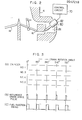
- FIG. 2 The arrangement of the air bypass passage 26 and the bypass valve 80 is shown more clearly in Fig. 2. It can be seen that the bypass passage 26 extending across the throttle valve 16 is closed or opened by the bypass valve 80 driven by the drive unit 82. In this connection, it should be noted that air flow section of the bypass passage 26 is varied by the lift or stroke of the valve element of the bypass valve 80, which stroke of the valve element of the bypass valve 80, which stroke is controlled by the drive unit 82 in dependence on the control input signal supplied from the control circuit 70. In other words, ON/OFF signal for controlling an armature.coil for driving the valve is periodically generated in the control circuit 70, while the armature coil controls the stroke or lift of the air bypass valve 80 in dependence on the ON/OFF signal.
- a fuel injection timing for the operation of the fuel injector is shown at (A) on the assumption that the engine is of a four-cylinder type.
- Rotation angle of the crank shaft is taken along I the abscissa.
- Suction strokes of the individual cylinders are indicated by hatched areas.
- the suction strokes of the four-cylinder engine are present for every 180° of the crank shaft, wherein the suction stroke for the first cylinder (No. 1) takes place in the range of the crank angle from 0° to 180°, the suction stroke for the third cylinder (No. 3) takes palces between 180° and 360°, the suction stroke for the fourth cylinder (No. 4) takes place between 360° and 540°, and the suction stroke for the second cylinder (No. 2) is carried out in a range of the crank angle from 540° to 720°.
- the reference crank angle pulse is generated for every 180° of the crank angle and utilized for opening the injector 12, the opening or injecting duration of which is arithmetically determined by the control circuit70 on the basis of the data available from the various measurements described hereinbefore.
- the injecting duration of the injector 12 is illustrated in Fig. 3 at (C)..
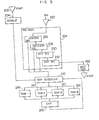
- Fig. 4 shows in a schematic diagram a general arrangement of a whole control system.
- the control system includes a central processing unit (hereinafter referred to as CPU) 102, a read-only memory (hereinafter referred to as ROM) 104, a random access memory (hereinafter referred to as RAM) 106, and an input/output interface circuit 108.
- the CPU 102 performs arithmetic operations for input data from the input/output circuit 108 in accordance with various programs stored in ROM 104 and feeds the results of arithmetic operation back to the input/output circuit 108.
- Temporal data storage as required for executing the arithmetic operations is accomplished by using the RAM 106.
- Various data transfers or exchanges among the CPU 102, ROM 104, RAM 106 and the input/output circuit 108 are realized through a bus line 110 composed of a data bus, a control bus and an address bus.
- the inptu/output interface circuit 108 includes input means constituted by a first analog-to-digital converter 119 (hereinafter referred to as ADC1), a second analog-to-digital converter 127 (hereinafter referred to as ADC2), an angular signal processing circuit 126, and a discrete input/output circuit 174 (hereinafter referred to as DIO) for inputting or outputting a single-bit information.
- ADC1 first analog-to-digital converter 119
- ADC2 second analog-to-digital converter 127
- DIO discrete input/output circuit 174
- the ADC1 includes a multiplexer 120 (hereinafter referred to as MPX) which has input terminals applied with output signals from a battery voltage detecting sensor 132 (hereinafter referred to as VBS), a sensor 56 for detecting temperature of cooling water (hereinafter referred to as TWS), an ambient temperature sensor 112 (hereinafter referred to as TAS), a regulated-voltage generator 114 (hereinafter referred to as VRS), a sensor 116 for detecting a throttle angle (hereinafter referred to as ⁇ THS) and a ⁇ -sensor 118 (hereinafter referred to as ⁇ S).
- MPX multiplexer 120
- VBS battery voltage detecting sensor 132
- TWS temperature of cooling water
- TAS ambient temperature sensor 112
- VRS regulated-voltage generator
- ⁇ THS a throttle angle
- ⁇ S ⁇ -sensor 118
- the multiplexer or MPX 120 selects one of the input signals to supply it to an analog-to-digital converter circuit 122 (hereinafter referred to as ADC).
- a digital signal output from the ADC 122 is held by a register 124 (hereinafter referred to as REG).
- AFS The output from-an air flow sensor 24 (hereinafter referred to as AFS) is supplied to the input of an ADC2 127 and converted into a corresponding digital signal through an analog-to-digital converter circuit 128 (hereinafter referred to as ADC).
- ADC analog-to-digital converter circuit 128
- REG register 130
- An angle sensor 146 (hereinafter termed ANGL) is adapted to produce a signal representative of a standard or reference crank angle, e.g. of 180° (this signal will be hereinafter termed REF signal) and a position signal representative of a minute crank angle (e.g. 1°) which signal will be hereinafter referred to as POS signal. Both of the signals REF and POS are applied to the angular signal processing circuit 126 to be shaped.
- the discrete input/output circuit or DIO 174 has inputs connected to an idle switch 148 (hereinafter referred to as IDLE-SW), a top-gear switch 150 (hereinafter termed TOP-SW) and a starter switch 152 (hereinafter referred to as START-SW), respectively.
- IDLE-SW idle switch 148
- TOP-SW top-gear switch 150
- START-SW starter switch 152
- a fuel-air ratio control device 132 (hereinafter referred to as INJC) serves for varying the duty cycle of the pulse signal applied to the injector 12 thereby to control the fuel injection quantity in the case of the embodiment being described.
- the INJC 132 includes a register 134 (hereinafter referred to as INJD) for setting the data representing the duty cycle described above.
- INJD a register 134
- the pulse having a pulse width corresponding to the fuel quantity to be injected is prepared by the INJC 132 and applied to the injector 12 through an AND gate 138.
- An ignition pulse generator circuit 139 (hereinafter referred to as IGNC) is provided with a register 140 (hereinafter referred to as ADV) for setting therein ignition timing data and a register l42 (hereinafter referred to as DWL) for controlling a duration of the primary current flowing through the ignition coil. Data for these controls are available from the CPU 102.
- the output pulse from the IGNC 139 is applied to the ignition system 154 through an AND gate 144.
- a pulse generator circuit 164 for producing a pulse signal to control the quantity of exhaust gas to be recirculated (EGR) includes a register 168 (hereinafter termed EGRP) for setting the pulse repetition period and a register l66 (hereinafter termed EGRD) for setting the duty cycle of the pulse signal which is supplied to the air solenoid valve 82 through AND gates 170 and 172 the AND gate 170 has the other input supplied with the output signal DIOl from the DIO 174. More specifically, when the signal DI0l is at a level "L", the AND gate 170 is enabled to conduct through the AND gate 172 the control pulse signal for controlling the air solenoid valve 82.
- EGRC pulse generator circuit 164 for producing a pulse signal to control the quantity of exhaust gas to be recirculated
- the DIO 174 is an input/output circuit for a single bit signal as described hereinbefore and includes to this end a register 176 (hereinafter referred to as DDR) for holding data to determine the output or input operation, and a register 178 (hereinafter referred to as DOUT) for holding data to be output.
- DDR register 176
- DOUT register 178
- the DIO 174 produces an output signal DIOO for controlling the fuel pump 32.
- a register 190 serves to hold therein commands for designating various internal states within the input/output circuit 108.
- MOD serves to hold therein commands for designating various internal states within the input/output circuit 108.
- all of the AND gates 138, 144, 172 and 184 can be enabled or disenabled by a command set at the register MOD 190.
- the outputs from the INJC, IGNC, EGRC etc. can be selectively initiated and inhibited by setting corresponding commands at the MOD register 190.
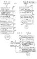
- Fig. 5 illustrates a program system for the control circuit shown in Fig. 4.
- the CPU 102 is set in a start mode (step 202) to execute an initialization program (INITIALIZ) 204.
- IITIALIZ initialization program
- ADC1 119 is initiated for converting a predetermined analog data of those applied thereto into a corresponding digital value which data is fetched upon occurrence of ADC1 END interrupt indicating the completed A-D conversion.
- operations for fetching or sampling other input analog data in term of the corresponding digital values are successively repeated.
- the state of a starter motor switch is observed by ISTRT program and an activation request of ADC1IN is set. These operations are successively repeated.
- the background jobs include, for example, a task for calculating the quatnity of EGR (hereinafter referred to as EGR CAL. TASK) and a task for calculating an air bypass quantity (hereinafter referred to as ISC TASK).
- EGR CAL. TASK a task for calculating the quatnity of EGR
- ISC TASK an air bypass quantity
- the program IRQ ANAL is constituted by an end interrupt processing program 226 for the ADC1 (hereinafter referred to as ADC1 END IRQ), an end interrupt processing program 228 for the ADC2 (hereinafter referred to as ADC2 END IRQ), an interval interrupt processing program 230 (hereinafter referred to as INTV IRQ) and an engine stop interrupt processing program 232 (hereinafter referred to as ENST IRQ), and issues activation request (hereinafter referred to as QUEUE) to the tasks to be activated among those described below.
- ADC1 END IRQ an end interrupt processing program 228 for the ADC2
- ADC2 END IRQ an interval interrupt processing program 230
- ENST IRQ engine stop interrupt processing program 232
- QUEUE activation request
- the tasks to which the request QUEUE is issued from tha- - rogram IRQ ANAL 224 are task 1 to task 13 denoted by 246 to 258 in Fig. 5.
- the numbers attached to these tasks represent the sequence of significances or priorities allotted to them in accordance to which the tasks are to be executed.
- the task to which the request QUEUE from the ENST IRQ program 232 is issued is a task 262 for processing the stopping of the engine (this task will be hereinafter referred to as ENST TASK).
- ENST TASK 262 When the task ENST TASK 262 has been executed, the control program is set back to the start mode and the start step 202 is regained.
- a task scheduler 242 serves to determine the sequence according to which the tasks are executed so that the task to which the request QUEUE is issued or execution of which are interrupted are executed starting from the task of the highest priority.
- a termination indicating program 260 (hereinafter referred to as EXIT) is executed to inform this fact to the task scheduler 242. Subsequently, the task of the next highest priority among those in queue is executed and so forth.
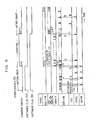
- Each of the programs ADC2IN, ADC2ST and RPMIN are activated upon every occurrence of INTV IRQ which is periodically generated at a time interval of 10 m-sec.
- the programs INJ, IGNCAL and DWLCAL are activated for every INTV IRQ which is generated at a time interval or period of 20 m.sec.
- the program MONIT is activated for every INTV IRQ generated at a time interval or period of 40 m ⁇ sec.
- the programs ADClIN and ADC1ST are activated for every INTV IRQ generated at a time interval of 50 m ⁇ sec.
- the EGRCAL program and ISC program are for the background jobs.
- the values (hereinafter referred to as TTM) representing the periods or time intervals at which the individual programs are activated by a timer counter are stored in ROM 104 at addresses B200 to B2FF.
- the starter switch When the starter switch is turned on, this fact is detected in ISTRT task and then the flag IST is reset (i.e. bit at the bit position for the software flag IST in RAM is reset tc zero), while a soft timer for the programs ADC2IN and MONIT is activated by the program ISTRT with the inhibition of IRQ for these programs being removed, and the activation request is issued to the programs MONIT and ADC2IN. Thereafter, the programs ADC2IN, ADC2ST and MONIT are periodically activated at predetermined time intervals, respectively. The fuel quantity and the ignition timing at this time point are arithmetically determined through execution of the program MONIT. The program ADC1IN is executed at the predetermined time interval. When the output from ADC1 has all been fetched, the activation request is issued only to the program HOSEI. Now, the period during which the starter switch is turned on (i.e., the starter motor is driven) is referred to a starting state.
- the starter switch When the starter switch is turned off, the engine is in the self-running state. At this time point, the software flag EM is cleared, while the programs INJ, IGNCAL and DWLCAL are initiated by the program MONIT. These programs are subsequently activated periodically at the predetermined respective time intervals. Simultaneously, the soft timer for the program MONIT is stopped, while all the other soft timers are activated. Consequently, subsequent activations of the tasks take place in response to the occurrence of the associated INTV IRQ's.
- a standby area to which the contents of CPU is transferred upon occurrence of IRQ is provided in RAM 106, as is shown in Fig. 16.
- the contents of RAM 106 are all cleared.
- the registers of the input/output interface circuit 108 are initialized (i.e. loaded with initial values). This initialization step includes setting of initial value of the angle sensor 146, setting of DDR of DIO 174, setting of detection period for issuing of ENST IRQ, and setting of measuring time for detecting the revolution number of the engine.
- the program ADC1 END is triggered.
- a level "H" is set at a flip-flop 276 in Fig. 27 constituting the mask register 200 shown in Fig. 4, as the result of which ADC1 END interrupt request is thereafter allowed to be issued for executing the program ADC1IN.
- ADC2 END IRQ is inhibited by setting the inhibition command for ADC2 END IRQ at the MASK register 200. Namely, a level "L” is set at a flip-flop 266 in Fig. 27 constituting the MASK register.
- software flags IST, EM are set in the RAM 106 shown in Fig. 16. When the step 287 is terminated, the program proceeds to the task scheduler to await appearance of ADC2 END IRQ.
- the program ADC1IN is illustrated in the flow chart shown in Fig. 8.
- the program ADC1ST is activated at the step 284 shown in Fig. 7, jump is made to the start address of the program ADlST by the execution of TASK SCHEDULER 242.
- the output signal from the VBS (battery voltage detecting sensor) 132 which constitutes one of the inputs to MPX 120 of the ADCl l19 shown in Fig. 4 is selected and applied to the input of the ADC 122.
- issue of ADC1 END IRQ is waited.
- a step 288 data is fetched from the register 124 and set in a data area DATA VB of RAM 106 in Fig. 16,
- the program ADC1ST is activated to select the sensor 56.
- a step 290 it is ascertained whether all the output values from the sensors 132, 56, 112, 114, l16 and 118 have been fetched. Since only the fetching of the output signal from the sensor 132 has been completed in this case, the routine is returned to the EXIT step, whereby the program ADC1ST is again started.
- the MPX 120 thus selects the output from the water temperature sensor TWS 56 as the next input thereto.
- the program ADClIN is executed in response to issuing of ADC1 END IRQ, whereby the digital value representative of theoutput from the sensor TWS 56 held in the register or REG 124 is read out and stored at DATA area DATA TW in RAM 106.
- the program proceeds to the EXIT step and then the routine is returned to the ADC1ST program by the TASK SCHEDULER. In this manner, through execution of the programs ADC1ST and ADCIIN in a looped routine, the digital.values representing the outputs from the sensors, respectively, are successively fetched.
- the program proceeds to a step 291 at which a level "H" is set at each of bit positions Q12 and Q13 of RAM 106 in Fig. 16 for requesting the programs HOSEI and ISTRT to be activated, and then these programs are executed according to the program of the task scheduler.
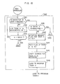
- Fig. 9 is a flow chart of the program ISTRT.
- the ignition timing for starting the engine is arithmetically determined and set.
- the ignition timing BADV(ST) is arithmetically determined as a function of the temperature TW of engine cooling water.
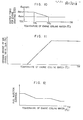
- the relationship between the ignition timing for starting the engine and the cooling water temperature is graphically illustrated in Fig. 10.
- the ignition timing ⁇ ADV(ST) is arithmetically determined. The results as obtained are loaded in the register ADV 140 of IGNC 139 shown in Fig. 4.
- the initial value for the fuel injection time is arithmetically determined.
- the arithmetic operation is executed in accordance to the relationship between the fuel injection time and the temperature of engine cooling water such as shown in Fig. 12.
- the result of the arithmetic operation is placed in the register INJD 134.
- step 293 it is checked whether the starter switch is closed or not by monitoring a bit DIO 5 of the DIO 174 shown in Fig. 4.
- the engine starting performance is additionally improved by virtue of the fact that activation request Q is issued to the programs ADC1IN and MONIT in response to the closing of the starter switch, whereby the arithmetic operation for determining the ignition timing is effected on the update data.
- activation request Q is issued to the programs ADC1IN and MONIT in response to the closing of the starter switch, whereby the arithmetic operation for determining the ignition timing is effected on the update data.
- the fetching of data and calculation would be delayed for the respective predetermined timer interval period in the worst case, to degrade the starting performance of the engine.
- the computer can be utilized fully in a useful manner.
- activation request is issued also to the programs ADClST and MONIT at a step 294. Additionally, soft timers for the programs ADC2IN and MONIT are started. Thereafter, activation requests for the programs ADC2IN and MONIT are generated automatically at the activation timings stated in the Table 1.
- a bit of high level "H” or logic "1" is set at the zeroth bit position of the DOUT register 178 of DIO 174 for initiating the operation of the fuel pump 32.
- the zeroth bit output DIO 0 of DIO is of high level, resulting in that the fuel pump is electrically energized.
- the first bit of the DOUT register 178 is set at low level "L”.
- the air bypass valve 82 is controlled by the output from the EGRC circuit 164. In practice, the setting of the zeroth bit and the first bit of the DOUT register 178 described above is effected simultaneously.
- bit of high level "H" is set at a mode register 190 described hereinafter, as the result of which the pulse outputs are supplied to the various control devices.
- the software flag IST is reset. In other words, bit "0" is set at the IST flag area in RAM 106 shown in Fig. 16.
- Fig. 13 shows a flow chart of the program MONIT.
- Activation request to this program is issued periodically at a time interval of 40 m.sec.
- the starter switch is opened. If the result is negative or "NO”, it is counted how many times this step is repeated at a step 303. In other words, it is determined how many times (N) the program MONIT has been activated.
- the fuel quantity as well as the ignition timing and the current flow initiating time of the ignition coil are arithmetically determined. The arithmetic operation for determining the ignition timing is effected as a function of the temperature of engine cooling water, as is illustrated in Fig. 10.
- the current flow initiating time of the ignition coil is determined.
- the fuel quantity and the current flow initiating time are greatly influenced by the variation of a battery voltage.
- the battery voltage decreases greatly in a starting period during which the starter motor is driven.
- MONIT program is executed every 50 m.sec.
- data of the sensors 132, 56, 112 - 118 may be sequentially fetched with a time interval of about 25 m.sec., and then those data fetched from ADC1 can sufficiently trace the sudden change of the battery voltage.
- Activation request for MONIT program is issued by setting a level "H” or "1" at a bit position Q7 of RAM 106 every 50 m ⁇ sec. and then MONIT program is executed in TASK SCHEDULER, as described hereinafter.
- QUEUE flag set at the bit position Q7 is reset, and RUN flag is set at a bit position R7.
- a level "L” or “0” and a level “H” or “1” are set at the bit positions Q7 and R7, respectively.
- QUEUE flag is set again at the bit position Q7.
- MONIT program is executed every 50 m ⁇ sec.
- a level "H" is set at each of bit positions Q4 and Q5 to activate the programs INJ, DWLCAL and IGNCAL, and at the same time data of TTM 4 and TTM 5 are set in COUNTER 4 and COUNTER 5 respectively to start the associated soft timers in Fig. 16.
- the content of the COUNTER 7 is made "0" to inhibit the soft timer for the program MONIT, while data of TTM 1 to TTM 9 except for TTM 7 are set in COUNTER 1 to COUNTER 8 except for COUNTER 7 respectively to activate all the other soft timers.
- a flip-flop 762 in Fig. 27 is reset to set command for inhibiting ADC1 END IRQ at the MASK register 200.
- a level "H” or "1" is set in a flip-flop 745 in Fig. 27 to remove inhibition of ENST IRQ. Accordingly, after the step 308, the engine stop can be detected by the ENST IRQ now released.
- the software flag EM is reset.
- the bit at the EM FLAG area of RAM shown in Fig. 16 is set to "0".
- termination or end indication is made by resetting the bit position R7 in EXIT program.
- the engine is in the self-running state controlled by the various programs activated by the associated timers.
- the timer for activating that task is simultaneously started, to thereby assure a smooth engine control.
- the software flags IST and EM are used for discriminating the states before, during and after the starting operation of the engine in the control for activating the various tasks.
- the task ISTRT for determining the fuel injection time or duration for the starting operation is processed together with the associated tasks ADC1IN and HOSEI.
- the activation request Q is issued from this task to the other tasks HOSEI and ISTRT.
- the tasks HOSEI and ISTRT are processed in this order, and an activation request is issued to the task ADClIN at the end of the task ISTRT.
- the sequence of the tasks ADClIN, HOSEI, ISTRT and again ADC1IN is executed in this order before the starting of the engine.
- the starter switch When the starter switch is turned on, operation is in the engine starting mode, wherein the activation requests are issued from the task ISTRT to the other task programs ADClIN, MONIT and ADC2IN.
- the task ADC1IN is activated by the activation request Q and the task ADC2IN is periodically activated at a predetermined time interval from the associated soft timer, while the task MONIT is activated either by the activation request Q or the soft timer T.
- the soft timer T Assuming that only the soft timer T is used, a delay corresponding to the predetermined timing interval will be involved in the worst case, making it impossible to attain an optimum fuel injection to a great disadvantage for the starting performance of the engine.
- the program 224 for analyzing the causes of IRQ comprises subprograms for the processing of ADC1 END IRQ 226, the processing of ADC2 END IRQ 228, the processing of INTV IRQ 230 and the processing of ENST IRQ 232.
- the contents of the associated IRQ as issued has to be at first examined. To this end, the contents in the STATUS register 198 shown in Fig. 4 is examined for determining the cause for the IRQ having been issued.
- the subprograms 226, 228, 230 or 232 is executed, as the result of which the activation request QUEUE is issued to the TASK required to be executed among the tasks 1 to 9.
- ADC2 END IRQ 228 is originally inhibited. More specifically, at the step 286 of the program INITIALIZ shown in Fig. 7, the MASK register is so set that ADC2 END IRQ is inhibited. The ADC2 END IRQ is caused to remain as inhibited by preventing the IRQ inhibition removal command from being issued.
- FIG. 14 An example of the program 224 is shown in Fig. 14. This program proceeds from the entry step 222 to a step 500 where it is decided whether IRQ being currently issued is ADCl END IRQ. If negative or "NO”, it is checked at a step 502 whether the software flag EM in RAM shown in Fig. 16 is "1" or not. When this flag is "0", this routine proceeds to the task scheduler. On the other hand, when the flag is "1", an activation request is issued to the program ADGlIN at a step 504. To this end, a flag "1" is set at the bit position b6 or Q8 of the task control word TCW8 in RAM 106 shown in Fig. 17. Thereafter, the task scheduler 242 is regained.
- the ADC1 END IRQ is allowed to be generated only in the state before the engine start or in the course of starting the engine as shown in Fig. 6. Otherwise, ADC1 END IRQ is inhibited.
- the program proceeds to a step 506 at which it is decided whether IRQ being currently issued is ADC2 END IRQ. If the result of the decision at the step 506 is "YES”, the program proceeds to the task scheduler. Otherwide, the step 508 is executed, whereby ADC2 END IRQ is inhibited in all the engine state.
- Step 508 it is decided whether the IRQ being currently issued is the INTV IRQ. If affirmative, the program proceeds to a step 509. Steps 509 to 518 are imparted with functions to determine the task program to be activated by the INTV IRQ among the tasks 1 to 9.
- step 509 it is decided whether the content of COUNTER 1 corresponding to the task 1 is "0" or not at a step 509.
- the decision at the step 509 leads to "YES”
- the program proceeds to a step 516 without setting a flag "1" at a bit position Ql.
- a step 516 retrieval of the activation timing for the program of the task 2 is effected in place of the task 1. If the result of the decision at the step 509 is "NO”, the program proceeds to a step 510.
- the task control word for the task 1, i.e. a counter constituted by the bit positions b0 to b5 of TCW1 shown in Fig. 15 is decreased by 1.
- the activation timings for the TASK's 1 to 9 listed in the Table 1 are set, respectively, in the counters 1 to 9 corresponding to the counters 1 to 9 of TCWl to TCW9 in RAM 106, respectively. Since INTV IRQ is assumed to be periodically generated at a time interval or period of 10 m.sec., the initial values set at the counters 1 to 9 are equal to 1, 1, 1, 2, 2, 2, 4, 5 and 5, respectively.
- the contents of the counter 1 of TCW1 is compared with that of the task activating timer TTM1 shown in Fig. 16.
- the bits b6 of every TCW represent the flags for requesting the activation of the associated tasks.
- the data in TTMl is set in the bit positions b0 to b5 of the COUNTERl of TCW1 (i.e. the initial value "1" is set), because the flag "1" is set at b6 of TCW1, i.e. Ql, at the step 514.
- step 516 retrieval of the activation timing for the program of task 2 is effected in place of the task 1.
- the program proceeds to the step 510, at which the contents of the counter 2 of TCW2 in RAM 106 shown in Fig. 16 which is the task control word for the program of task 2 is decreased by "1".
- the decreased contents is compared with the contents of TTM2 of ROM 104 shown in Fig. 16.
- the program proceeds to a step 520 at which it is decided whether the IRQ in question is ENST IRQ.
- the decision made at the step 508 leads to "NO"
- the IRQ must necessarily be ENST IRQ. Accordingly, the step 520 may be omitted and the program may proceed directly to the step 522 at which the fuel pump is stopped in accordance with a specific program based on the engine stop. Additionally, all the output signals for the ignition system and the fuel supply control system are reset. The program then returns to the start step 202 shown in Fig. 5.
- Fig. 15 shows in detail in a flow chart a program for the task scheduler 242.
- n 1. Accordingly, decision is made as to the necessity of TASK1 being executed. In other words, presence of the task activation request is examined in the order of high to low priority levels. Such examination can be made through retrieval of a bit b6 or a flag Q and a bit b7 or a flag R of the respective task control words. Bit position b6 is allotted to the activation request flag. When “1" is present at this position b6, it is determined that the activation request is present. Further, b7 is allotted for the flag indicating that the associated task is under execution. The presence of "1" at b7 indicates that the associated task is under execution and is now being interrupted. Accordingly, when "1" is present at least one of b6 and b7, the scheduler program proceeds to a step 538.
- the flag set at b7 is checked.
- the presence of "1" at b7 means that the execution is being interrupted.
- the execution being interrupted until then is regained.
- Flag set at both b6 and b7 cause the decision at the step 538 to be affirmative or "YES", whereby the task program being interrupted is re-initiated.
- the activation request flag of the task is cleared at a step 552, which is followed by a step 544 where the flag is set at b7 (this flag will be hereinafter referred to as RUN flag).
- the steps 542 and 544 show that the activation request for the task proceeds to the state in which the task is to be executed.
- the start address of the task program in concern is reprieved.
- This address can be determined from a start address tables TSA provided in ROM 104 in correspondence to TCW's of the various tasks. By jumping to the start address as determined, the execution of the task program in concern takes place.
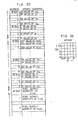
- Fig. 16 illustrates relationship between the task control words TCW, the TTM representing the task activation time internals or periods and task start address tables TSA provided in the RCM.
- the task control words TCWl to TCW9 there are stored in ROM the task activating periods TTMl to TTM9.
- COUNTER's are updated successively and a flag is set at b6 of the associated TCW upon coincidence between contents of the counter and TTM for the task.
- the flag is thus set, the start address of the task is retrieved from the task start address TSA. Jump is made to the retrieved start address, whereby the selected one of the programs is executed.
- a flag is set at b7 of the TCW in RAM 106 which corresponds to the program being executed. Thus, so far as this flag is set, it is decided that the associated program is being executed. In this way, the program for the task scheduler 242 shown in Fig. 5 is executed. As the consequence, one of the task programs 246 to 258 is executed.
- IRQ is issued during the execution of the any task program, the execution is interrupted again to deal with the IRQ. Assuming that no IRQ is issued, the processing of the task being instantly executed will come to an end.
- EXIT program 260 is next executed.
- the tasks 12 and 13 are for the background jobs which are not activated by INTV IRQ. However, these tasks can be altered to the ones which can be activated by INTV IRQ.
- predetermined activation timings may be initially set at the task control words TCW 12 and TCW 13 corresponding to the tasks 12 and 13, while the bit values of TTM's 12 and 13 provided ccrrespondingly to the of TTM's 12 and 13 provided correspondingly tasks 12, 13 are set to "0". Thereafter, the steps 509 to 518 illustrated in Fig. l4 are repeated until n becomes equal to 11.
- the initial value of the counter of the corresponding TCW may be set to "0" so that the value of the counter will not coincide with the value of the corresponding TTM (i.e. "0") at the step 512.
- the tasks for the background jobs and the tasks activated by INTV IRQ can be arbitrarily altered to each other through corresponding modification only of the task programs to be altered without necessity to alter the other programs. Further, selective alteration of the activating timings of the individual tasks activated by INTV IRQ can be effected without altering the other programs.
- method of determining the fuel injection quantity, ignition timing, etc. on the basis of proportional expressions may be replaced by the method in which maps are utilized, and vice versa.
- interrupt in synchronism with crank rotation may be employed in place of the timer for activating the task program.
- the activation periods as required are initially set at the counters of the associated TCW's, while for the tasks to be inhibited from activation, initial values "0" are set at the counters of the corresponding TCW's.
- the EXIT program 260 is illustrated in detail in Fig. 17. This program is composed of steps 562 and 564 for identifying the ended task. At the steps 562 and 564, retrieval is made successively starting from the task 1 to identify the ended task. At the next step 568, the flag RUN set at b7 of TCW corresponding to the ended task is reset, which means that the program for the identified task has been completely terminated. The processing is taken back again by the task scheduler 242, whereby the program next to be executed is determined.
- a flag "1" is set at each of bit positions Ql, Q2, Q3 of TCWl, TCW2, TCW3 at time t2, while b6 of TCW1 or Ql is cleared, whereby the program for the task 1 is executed.
- flag "1" is set also at b6 of TCW4 or Q4.
- the programs first to be executed are the programs for the tasks 1, 2 and 3 becuase of the higher priorities thereof than the task 4.
- the OS program is regained to clear the flag at b7 of TCW1 or Rl and the request for executing the program of task 2 of the next high priority is accepted with preparation being made for the execution.
- the OS program is regained, and the flag at b7 of TCW2 or R2 is cleared, whereupon the program for the task 3 is allowed to be executed.
- execution of the task 3 comes to an end, the OS program is regained, and the flag at b7 of TCW3 or R3 is cleared. Then request for executing the task 4 next to be executed is detected with preparation for execution being made. This program begins to be executed at t4.
- the task scheduler program 242 is executed to search possible activation request to the task programs as well as to the program being interrupted. For example, it is assumed that flag "1" set at b6 of TCW7 corresponding to the task 7, which is activated for every 50 m.sec., is identified. Then, the start address for the task 4 is retrieved from TSA7 and jump is made to the retrieved start address at which the task 7 program begins to be executed. At this time, flag at b6 of TCW7 is cleared while flag "1" is set at b7 of TCW7. When execution of the task 7 is ended at a time point tll, OS program is regained, whereupon EXIT program is executed to clear the flag set at b7 of TCW7.
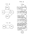
- Fig. 19 The manner in which one of the programs 246 to 258 is executed in accordance with the procedures described hereinbefore in conjunction with Figs. 5 and 18 is illustrated in Fig. 19.
- a standby state labelled by IDLE no request to activate a program is issued.
- a flag "1" is set at b6 of the associated TCW to indicate the necessity of activation.
- the time duration required for the shift from the state IDLE to QUEUE is determined in dependence on the task to which the activation request is issued.
- sequence of execution is determined in accordance with the priority allotted to the programs.
- the flag at b6 of the associated , TCW has to be beforehand cleared while the flag must be set at b7.
- the state in which program is executed is represented by RUN in Fig. 19.
- the flag at b7 of the associated TCW is cleared to indicate the completed termination of the executed program.
- the state RUN is now replaced by the state IDLE for awaiting a next activation request.
- IRQ is issued during execution of RUN of a program
- the program has to be interrupted.
- the contents present at that time in CPU is set aside at a standby area.
- This state is indicated by a label READY.
- the interrupted program is to be executed again, the contents in the standby area is fed back again to CPU.
- the state READY is changed again to the state RUN.
- each of the program may take repeatedly the four states shown in Fig. 19.
- 19 is a typical one. It may happen that a flag "1" is set at b6 of TCW in the state READY. For example, this is the case in which a next activation request makes appearance to the very program that is being interrupted. Under the situation, the flag set at b7 is allotted with a higher preference over the flag set at b6. Accordingly, the task program being interrupted is first executed. When the flag at b7 is reset, the just executed program is shifted directly to the state QUEUE without taking the state IDLE.
- the standby area may be provided in correspondence to the individual task programs.
- the standby area is provided in correspondence to the individual tasks. It will be understood that the program which is interrupted due to the interrupt request or to be replaced by other program for executing desired subroutine is set aside at the standby area.
- Fig. 20 illustrates the shifting in the state of the background job program.
- an IRQ is issued during execution of this program, i.e. in the state RUN
- the contents in CPU is set aside at the relevant standby area, whereby the state READY is taken.
- the interrupt request has been processed
- the contents in the standby area is fed back to CPU, whereby the state RUN is regained.
- the standby area as indicated in Fig. 20 can be used for this purpose.
- Fig. 21 is a flow chart of the INJ program which is activated at a time interval or period of 20 m.sec.
- the digital value QA representing the output signal from the air flow meter 24 and stored in RAM 106 through execution of the task ADC2IN after A-D conversion is.read out.
- the actual value of QA read out at the step 570 is compared with QA values set at xn of AF map provided in ROM 104 shown in Fig. 22, thereby to determine n of x n corresponding to the actual value of QA.
- Fig. 23 shows a scheme of the AF map.
- the engine speed data N stored in RAM through execution of the task RPMIN is read out.
- the actual value of N as read out is compared with the values of N set at y n in the AF map, thereby to determine n of y n corresponding to the actual value of N.
- an address of the AF map is determined on the basis of x n and y n determined at the steps 572, respectively.
- the fuel supply quantity stored at the determined address is read out and placed in the register INJD 134 shown in Fig. 4 at a step 580.
- Fig. 24 shows a flow chart of the program IGNCAL.
- digital value QA representing the output from the air flow meter and stored in RAM through execution of the program ADC2IN is read out.
- the actual value of QA as read out is compared with values of QA set at x n of ADV map provided in ROM 104 as shown in Fig. 22, thereby to determine n of x n which corresponds to the actual value of QA.
- the engine speed data N stored in RAM through execution of RPMIN is read out.
- the actual value of N as read out is compared with values of N set at y n of the ADV map thereby to determine n of Y n which corresponds to the actual value of N.
- an address in the ADV is determined on the basis of x n and y n determined at the steps 588 and 592, respectively.
- the ignition timing stored at the determined address is read out and placed in the register ADV 140 shown in Fig. 4.
- the program HOSEI is provided for determining correction coefficients for temperatures of the atmosphere and cooling water, for example. Since these parameters undergo only slow changes, it is sufficient to determine the correction coefficients at a long interval.
- the program ADC2IN is disclosed, for example, in U.S. Serial No. 952275 filed October 18, 1978 in the name of Masao Takato et al under the title "Input Signal Processor Used in Electronic Engine Control Apparatus” and assigned to HITACHI LTD and U.S. Serial No. 78468 filed September 24, 1979 in the name of Takao Sasayama et al under the title "Hot-Wire Flow Rate Meassuring Apparatus” and assigned to HITACHI LTD.
- the program RPMIN is disclosed in U.S. Serial No. 952275, for example.
- the program DWLCAL is disclosed, for example, in U.S. Application filed 1980 in the name of Toshio Furuhashi under the title "Method for controlling an internal combustion engine” and assigned to HITACHI LTD.
- Program ISC is provided for controlling the opening degree of the air bypass valve 82 in the idling operation.
- Fig. 25 shows the details of this program.
- the air bypass valve 82 is designated.
- the air bypass valve is controlled in dependence on the value placed in the register EGRD 166.
- the air bypass valve 82 serving for controlling the air flow thorugh the bypass passage is controlled in the specific operating conditions. More particularly, in the case of operation at a low ambient temperature such as in winter, starting operation in the cooled state of engine, operation under large load due to the use of a ear air-conditioner or the like, the air flow through the bypass passage is increased.
- the duty factor of the air bypass valve is determined and set at the register EGRD 166 in dependence on the temperature of engine cooling water in accordance with the characteristic shown in Fig. 11.
- step 604 it is decided whether the idle switch is closed or not. If the switch is closed, then activation request flag for the program ISC is set at a step 606. In other words, bit "1" is set at Q10 of the task control word TCW10 of RAM shown in Fig. 16. Simultaneously, the first bit of the register DOUT of DIO 174 is set at level "L".
- Fig. 26 shows a flow chart of the program EGRCAL.
- EGR system for controlling the exhaust gas recirculation quantity is driven.
- the first bit in the register DOUT 178 of DIO is set to the level "H" at a step 610, whereby the EGR system 188 is driven in accordance with the value set at the register EGRD 166.
- arithmetic operation for determining EGR quantity is carried out.
- EGR operation is inhibited or cut.
- zero is set at the EGRD register for effecting EGR CUT at a step 616.
- the program proceeds to the step 614 where it is decided whether the temperature TW of cooling water is lower than a predetermined value TB °C. If so, then EGR operation is inhibited.
- zero is set at the EGRD register at a step 6l6.
- the temperature TA at the step 612 represents the upper limit
- the temperature TB at the step 614 represents the lower limit.
- the program proceeds to a step 618 where the EGR quantity is arithmetically determined on the basis of the suction air quantity QA and the revolution number N of the engine through the map retrievals.
- the map employed for this retrieval is provided in ROM 104 al addresses B601 to B700, as is shown in Fig. 16.
- the retrieved values are set at the register EGRD.
- the valve for EGR is opened in dependence on the value placed in the register EGRD and the duty cycle previously set at the register EGRP, whereby EGR.operation is carried out.
- a step 622 it is decided whether the idle switch is in the closed state by monitoring the DIO 174.
- activation request flag for the program EGRCAL is set.
- the bit "1" is set at Qll of the task control word TCWll of RAM.
- the first bit of the register DOUT 178 of the DIO is set at the level "B".
- the program EGRCAL is processed as the background job as in the case of the program ISC in the sense that the activation request for this program is set by itself and then the end indication is made.
- the step 606 in the case of the program ISC is omitted while the step 604 is executed before the step 600 so that the steps 600 and 602 are executed only when the idle switch is closed.
- the activation timing or period as desired is initially set at the COUNTER 10 of the task control word TCW 10 of RAM 106 corresponding to the program ISC. Similar procedure may be taken for altering the program EGRCAL to the program activated by INTV IRQ.
- bit "0" is initially set at the counter of TCW corresponding to that task, while an activation request flag "1" is set at b6 of TCW corresponding to the task at the end of the task program, which may then proceeds to the EXIT step.
- a task program may be changed between a background job program and the program activated by INTV IRQ by modifying only the program desired to be changed and the contents of associated TCW and TTM without modifying other programs.
- INTV IRQ is generated according to the teaching of the invention so that all the arithmetic operations for control may be carried out independently from revolution number of the engine.
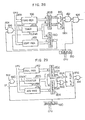
- An arrangement of a circuit for generating the IRQ is schematically shown in Fig. 27.
- flip-flops 739, 745, 762, 766 constitute respective bits of the MASK register 200 in Fig. 4 and flip-flops 740, 746, 764, 768 constitute respective bits of the STATUS register 198..
- a register 735 is loaded with data for setting the timer interrupt period (e.g. 10 m.sec.) from CPU through a data bus 752, while a counter 736 is concurrently supplied with clock pulses CLOCK.
- the data contents placed in the register 735 is compared with the count output from the counter 736 through a comparator 737 which produces an output signal upon coincidence of the contents between the register 735 and the counter 736.
- the output signal from the comparator 737 is used to set flip-flops 738 and 740. Simultaneously with the setting of the flip-flops 738 and 740, an output signal is produced from AND circuit 747, whereby the counter 736 as well as the flip-flop 738 are reset.
- the timer interrupt signal IRQ is produced through an AND circuit 748 and an OR circuit 751.
- the flip-flop 739 serves to mask the timer interrupt signal IRQ when this signal is unnecessary. At that time, the flip-flop 739 is supplied with a reset command from CPU.
- ENST interrupt request which is to be generated when the engine is stopped accidentally or due to fault is produced through a similar circuit arrangement as that for the timer interrupt, which comprises a register 74l, a counter 742, a comparator 743, AND circuits 749 and 750, and flip-flops 745 and 746.
- the signal supplied to the counter 742 is however the one generated during rotation of the engine.
- This signal is the reference angular signal REF produced from the sensor 146 shown in Fig. 4 and may be produced for every rotation of 180 0 of the crank shaft in the case of a four-cylinder internal combustion engine. Since the counter 742 is reset when the signal REF is produced, no ENST interrupt signal can be generated. However, when the engine is stopped for the reasons described above, REF signal will disappear, whereby the counter 742 is released from the reset state.
- the ENST interrupt signal can be generated in the manner described above in conjunction with generation of the timer interrupt signal.
- the timer interrupt signal IRQ triggers the activation of tasks as illustrated in the flow chart of Fig. 5, whereby the tasks are processed in accordance with the allotted priority levels. Namely, upon reception of an interrupt request, CPU analyses the cause for the received interrupt request. When the interrupt request is determined to be the timer interrupt, the tasks 246 to 258 allotted with priority are activated and the task selected through the task scheduler 242 is executed. When the execution of task is terminated, a corresponding indication is made through the execution of EXIT program. In response to the next timer interrupt signal, the task next to be executed is selected through the task scheduler.
- a flip-flop 764 is set to "1", when the sequence operation of ADC1 has been terminated.
- an AND gate 770 is then enabled to produce a service request signal to CPU for dealing with ADC1 END IRQ.
- the flip-flop 762 is not set to "1"
- ADC1 END IRQ is inhibited.
- the flip-flop 768 is set to "1".
- ADC2 END IRQ is generated through an AND gate 772 and the OR gate 751.
- the AND gate 772 remains disenabled, resulting in no ADC2 END IRQ of being generated. In this manner, only when the flip-flop 739, 745, 762 and/or 766 is set to "1", associated IRQ is issued and vice versa.
- Fig. 28 shows in detail EGRC 164 shown in Fig. 4.
- the content of the register ERGD shown in Fig. 4 represents the width of pulse and corresponds to a register 168 shown in Fig. 28. Further, there is provided a register 168 which corresponds to EGRP.
- a timer 804 constituted by a counter circuit counts clock signal from the AND gate 816.
- the count value B is compared with'the contents placed in the register 168 through a comparator 810.
- the timer 804 is reset. In this manner, the timer 804 repeats the count- ing operation at a period determined by the value C stored in the register 168.
- the count value of the timer 804 is compared with the value stored in the register 166 through a comparator 808.
- a flip-flop 812 is set.
- the flip-flop 812 is reset. In this manner, the time interval during which the flip-flop 812 is in the set state is determined by the value A stored in the register 166. By increasing the value A, the duration of the set state of the flip-flop 812 is correspondingly increased.
- the set output of the flip-flop 812 is repeatedly produced at a frequency corresponding to the value set at the register 168 and is output through the AND gates l82 and l84 enabled by the bit of level "H" at b0 of the mode register 190 if the input DIOl to the AND gate l82 is level "H".
- the start or stop of operation of the circuit shown in Fig. 28 can be controlled.
- the AND gates 184 and 816 are controlled by the bit at the position b0 of the mode register which bit is destined to control the EGRC 164 shown in Fig. 4.
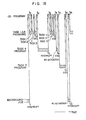
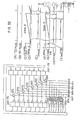
- Fig. 29 shows in detail a circuit arrangement of the IGNC 139 in Fig. 4.
- Data for controlling the time point at which the primary winding of the ignition coil is energized is loaded in the DWL register from CPU, while data for the ignition timing is set at the ADV register. It is assumed now that the value set at the DWL register 142 is represented by A, while the set value of the ADV register l40 is represented by C.
- the AND gates 144 and 860 are then enabled, i.e. in the conducting state, whereby POS pulses are applied to the counter 850 through AND gate 860. Consequently, the count value of the counter 850 is increased as a function of the engine crank angle and is cleared by the REF (reference) pulse.
- the count value at which the counter 850 is cleared by the REF pulse is represented by B.
- the flip-flop 856 When the count value of the counter 850 is increased beyond the value A set at the DWL register 142, the flip-flop 856 is set by the output pulse from the AND gate 864. The set output from the flip-flop 856 is then applied to the ignition system through AND gate l44, as the result of which a current flows through the primary winding of the ignition coil. When the count value is further increased, the flip-flop 856 is again reset by the output signal (C ⁇ B) from the comparator 854. Then, the pulse output from the AND gate 144 is interrupted, resulting in generation of spark for ignition.
- Fig. 30 shows in detail an arrangement of the DIO 174 described hereinbefore in conjunction with Fig. 4.
- the signal from the bit position of DDR 176 at which the bit "H" is set is applied to the associated one of tristates 872 to 886, whereby the associated tristate becomes conductive.
- bit of DOUT 178 which corresponds to the bit "H” in DDR is output through the associated tristate.
- signals present at lines DI00 to DI07 can be arbitrarily read by CPU through buffer amplifiers 892 to 904.
- the signals present at the lines corresponding to the non-conducting ones of the tristates 872 to 886 depend on the external conditions. Accordingly, the external conditions are read for these lines.
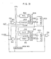
- Fig. 31 shows in detail an arrangement of the INJC 132 shown in Fig. 4.
- the REF pulse derived from the output of the crank angle sensor is produced at a predetermined crank angle (e.g. 80° or 90°) before reaching the top dead center (TDC). Relationship between the top dead center (TDC) of the crank and the REF pulse is illustrated in Fig. 32 at (A) and (B).
- TDC top dead center
- FIG. 32 On the assumption that the bit at the bit position b4 of the mode register 190 is at "H" level, gates 910, 912 and 138 are in the conducting state. Accordingly, the count value of a counter 904 is cleared by every REF pulse, as is illustrated in Fig. 32 at (C).
- a register 902 functions to receive and hold the value A from CPU. This value A is utilized to determine the time point at which the fuel injection is initiated. The value A is compared with the count value B through the comparator 906 to set a flip-flop 908.
- a pulse is supplied to the injection valve 12 through the AND gate 138.
- the gate 912 is opened, whereby a timer 916 constituted by a counter counts the clock pulses.
- a register 134 corresponds to the INJD register shown in Fig. 4.
- the injection valve is opened. More particularly, so far as the count value D of the timer 916 is smaller than the set value C, the flip-flop 920 is set. However, when C ⁇ D, the flip-flop 920 is reset to block the AND gate 138. Thus, the injection pulse is interrupted.
- the time point for initiating the fuel injection as well as the opening duration of the fuel injection valve can be controlled.
- the priorities of programs are determined in dependence on the functions of the tasks, wherein interval activation requests are issued in accordance with the priority.
- main tasks for controlling engine operation are activated at predetermined intervals independently from rotation speed of the engine. Accordingly, the load imposed to CPU may remain substantially constant to assure controls with high reliability and performances.
- the software flags 1ST and EM are provided to discriminate the before-start state, the starting state and the after-start state from one another, wherein two different activations, i.e. the activation request Q for the task program MONIT and the soft timer activation T are adopted upon transition from the before-start state to the starting state during which the starter motor is driven, while two different activations i.e. the activation request Q for the task programs INJ, DWLCAL and IGNCAL and the soft timer activation T are adopted upon transition from the starting state to the after-start state, whereby the starting performances are significantly enhanced.
- two different activations i.e. the activation request Q for the task program MONIT and the soft timer activation T are adopted upon transition from the before-start state to the starting state during which the starter motor is driven
- two different activations i.e. the activation request Q for the task programs INJ, DWLCAL and IGNCAL and the soft timer activation T are adopted upon transition from the starting state to the after-start state, where
- the individual task programs are adapted to be executed independently from one another, it is possible to set the activation periods arbitrarily for each of the task programs and additionally alter or modify the contents of the individual tasks without exerting influence to the contents of the other task programs. Besides, alteration of the tasks to the timer-activated programs and/or to the background job programs can be made in an arbitrary manner.
Landscapes
- Engineering & Computer Science (AREA)
- General Engineering & Computer Science (AREA)
- Chemical & Material Sciences (AREA)
- Combustion & Propulsion (AREA)
- Mechanical Engineering (AREA)
- Signal Processing (AREA)
- Theoretical Computer Science (AREA)
- Computer Hardware Design (AREA)
- Microelectronics & Electronic Packaging (AREA)
- Combined Controls Of Internal Combustion Engines (AREA)
- Electrical Control Of Air Or Fuel Supplied To Internal-Combustion Engine (AREA)
- Control Of Velocity Or Acceleration (AREA)
- Electrical Control Of Ignition Timing (AREA)
- Control By Computers (AREA)
Applications Claiming Priority (2)
| Application Number | Priority Date | Filing Date | Title |
|---|---|---|---|
| JP40934/79 | 1979-04-06 | ||
| JP4093479A JPS55134721A (en) | 1979-04-06 | 1979-04-06 | Electronic engine controlling method |
Publications (3)
| Publication Number | Publication Date |
|---|---|
| EP0017218A2 true EP0017218A2 (de) | 1980-10-15 |
| EP0017218A3 EP0017218A3 (en) | 1981-09-16 |
| EP0017218B1 EP0017218B1 (de) | 1987-07-15 |
Family
ID=12594325
Family Applications (1)
| Application Number | Title | Priority Date | Filing Date |
|---|---|---|---|
| EP80101756A Expired EP0017218B1 (de) | 1979-04-06 | 1980-04-02 | Elektronisches Steuerverfahren für Brennkraftmaschinen |
Country Status (4)
| Country | Link |
|---|---|
| US (1) | US4363097A (de) |
| EP (1) | EP0017218B1 (de) |
| JP (1) | JPS55134721A (de) |
| DE (1) | DE3071993D1 (de) |
Cited By (1)
| Publication number | Priority date | Publication date | Assignee | Title |
|---|---|---|---|---|
| EP0058561A3 (en) * | 1981-02-17 | 1983-10-12 | Honda Giken Kogyo Kabushiki Kaisha | Fuel injection control method |
Families Citing this family (16)
| Publication number | Priority date | Publication date | Assignee | Title |
|---|---|---|---|---|
| JPS5638542A (en) * | 1979-09-05 | 1981-04-13 | Hitachi Ltd | Controlling method for engine |
| DE3420316C2 (de) * | 1983-05-31 | 1997-01-09 | Canon Kk | Verfahren zur Steuerung eines Kopiergeräts |
| GB2141259A (en) * | 1983-06-03 | 1984-12-12 | Ford Motor Co | Automatic control of i.c. engines |
| US4633412A (en) * | 1984-04-26 | 1986-12-30 | At&T Bell Laboratories | Option protocol arrangement for stored program rectifier controller |
| US4599695A (en) * | 1984-05-25 | 1986-07-08 | Motorola, Inc. | Microprocessor transient interrupt system adaptable for engine control |
| US4777618A (en) * | 1984-07-19 | 1988-10-11 | Nippondenso Co., Ltd. | Method of storing, indicating or producing signals and apparatus for recording or producing signals |
| JPS62279245A (ja) * | 1986-05-29 | 1987-12-04 | Nissan Motor Co Ltd | 空燃比制御装置 |
| JPH07105801B2 (ja) * | 1986-10-02 | 1995-11-13 | 日本電装株式会社 | 車両用通信制御装置 |
| US4954948A (en) * | 1986-12-29 | 1990-09-04 | Motorola, Inc. | Microprocessor operating system for sequentially executing subtasks |
| JPH0833143B2 (ja) * | 1987-02-23 | 1996-03-29 | 三菱電機株式会社 | エンジンの制御装置 |
| US4991102A (en) * | 1987-07-09 | 1991-02-05 | Hitachi, Ltd. | Engine control system using learning control |
| JP2002519578A (ja) | 1998-06-30 | 2002-07-02 | シーメンス カナダ リミテッド | 噴射器egr弁及びシステム |
| JP4277396B2 (ja) * | 1999-11-30 | 2009-06-10 | 株式会社デンソー | 電子制御装置 |
| US6275766B1 (en) * | 1999-12-21 | 2001-08-14 | Ford Global Technologies, Inc. | System and method of reducing chronometric load |
| US7072757B2 (en) * | 2001-10-29 | 2006-07-04 | Caterpillar Inc. | Fuel control system |
| US20250036627A1 (en) * | 2023-07-25 | 2025-01-30 | Sap Se | Deepest-only scheduling |
Family Cites Families (19)
| Publication number | Priority date | Publication date | Assignee | Title |
|---|---|---|---|---|
| GB1397438A (en) * | 1971-10-27 | 1975-06-11 | Ibm | Data processing system |
| JPS4995548A (de) * | 1973-01-12 | 1974-09-10 | ||
| US3825902A (en) * | 1973-04-30 | 1974-07-23 | Ibm | Interlevel communication in multilevel priority interrupt system |
| JPS5063345A (de) * | 1973-10-05 | 1975-05-29 | ||
| US3969614A (en) * | 1973-12-12 | 1976-07-13 | Ford Motor Company | Method and apparatus for engine control |
| JPS50128429A (de) * | 1974-03-28 | 1975-10-09 | ||
| GB1468642A (en) * | 1975-01-07 | 1977-03-30 | Burroughs Corp | Data processing systems |
| US4001783A (en) * | 1975-03-26 | 1977-01-04 | Honeywell Information Systems, Inc. | Priority interrupt mechanism |
| US4091447A (en) * | 1976-07-19 | 1978-05-23 | Union Carbide Corporation | Interrupt control system for a microcomputer |
| US4152761A (en) * | 1976-07-28 | 1979-05-01 | Intel Corporation | Multi-task digital processor employing a priority |
| JPS5340105A (en) * | 1976-09-24 | 1978-04-12 | Nippon Denso Co Ltd | Automobile control unit |
| FR2384115A1 (fr) * | 1977-03-15 | 1978-10-13 | Renault | Calculateur numerique d'injection a microcalculateur |
| JPS6059418B2 (ja) * | 1977-05-31 | 1985-12-25 | 株式会社デンソー | 電子式燃料噴射制御装置 |
| JPS6060024B2 (ja) * | 1977-10-19 | 1985-12-27 | 株式会社日立製作所 | エンジン制御方法 |
| US4255789A (en) * | 1978-02-27 | 1981-03-10 | The Bendix Corporation | Microprocessor-based electronic engine control system |
| JPS54130734A (en) * | 1978-03-31 | 1979-10-11 | Nippon Denso Co Ltd | Engine electronic controller |
| US4245317A (en) * | 1978-06-22 | 1981-01-13 | The Bendix Corporation | Start and warm up features for electronic fuel management systems |
| DE2841750A1 (de) * | 1978-09-26 | 1980-04-03 | Bosch Gmbh Robert | Verfahren und einrichtung zum bestimmen der einzelnen stellgroessen einer brennkraftmaschine, insbesondere einer gasturbine |
| US4231091A (en) * | 1978-11-27 | 1980-10-28 | General Motors Corporation | Engine control system |
-
1979
- 1979-04-06 JP JP4093479A patent/JPS55134721A/ja active Granted
-
1980
- 1980-04-02 EP EP80101756A patent/EP0017218B1/de not_active Expired
- 1980-04-02 DE DE8080101756T patent/DE3071993D1/de not_active Expired
- 1980-04-07 US US06/138,086 patent/US4363097A/en not_active Expired - Lifetime
Cited By (1)
| Publication number | Priority date | Publication date | Assignee | Title |
|---|---|---|---|---|
| EP0058561A3 (en) * | 1981-02-17 | 1983-10-12 | Honda Giken Kogyo Kabushiki Kaisha | Fuel injection control method |
Also Published As
| Publication number | Publication date |
|---|---|
| EP0017218A3 (en) | 1981-09-16 |
| EP0017218B1 (de) | 1987-07-15 |
| JPH0213137B2 (de) | 1990-04-03 |
| JPS55134721A (en) | 1980-10-20 |
| DE3071993D1 (en) | 1987-08-20 |
| US4363097A (en) | 1982-12-07 |
Similar Documents
| Publication | Publication Date | Title |
|---|---|---|
| US4337513A (en) | Electronic type engine control method and apparatus | |
| EP0017218A2 (de) | Elektronisches Steuerverfahren für Brennkraftmaschinen | |
| US4482962A (en) | Engine control method | |
| US4354238A (en) | Method of controlling air-fuel ratio of internal combustion engine so as to effectively maintain the air fuel ratio at a desired air-fuel ratio of λ=1 | |
| EP0050364A2 (de) | Verfahren zum Steuern eines Verbrennungsmotors | |
| US4564907A (en) | Electronic control apparatus for internal combustion engine | |
| US4501249A (en) | Fuel injection control apparatus for internal combustion engine | |
| US4377137A (en) | Method for starting the operation of an internal combustion engine | |
| US4433650A (en) | System for controlling the starting operation of an internal combustion engine | |
| JPS5996455A (ja) | エンジン制御装置 | |
| EP0077533B1 (de) | Vorrichtung und Verfahren zur Regelung bei Brennkraftmotoren | |
| US4428051A (en) | Electronic control apparatus for internal combustion engine | |
| EP0350894A2 (de) | Vorrichtung zur Steuerung des Zündzeitpunktes bei einer inneren Brennkraftmaschine | |
| JPH0138176B2 (de) | ||
| JPS5974339A (ja) | 燃料噴射装置 | |
| US4522178A (en) | Method of fuel control in engine | |
| JPH0118443B2 (de) | ||
| JPS57206738A (en) | Electronic fuel injection controller of internal combustion engine | |
| KR850000119B1 (ko) | 전자식 엔진 제어방법 | |
| KR840000710B1 (ko) | 전자식 엔진 제어장치 | |
| JPH0118256B2 (de) | ||
| JPS5974337A (ja) | 燃料噴射装置 | |
| KR840001367B1 (ko) | 엔진 제어 장치 | |
| JPH0318026B2 (de) | ||
| JPS5841361A (ja) | 電子式エンジン制御装置 |
Legal Events
| Date | Code | Title | Description |
|---|---|---|---|
| PUAI | Public reference made under article 153(3) epc to a published international application that has entered the european phase |
Free format text: ORIGINAL CODE: 0009012 |
|
| AK | Designated contracting states |
Designated state(s): DE FR GB |
|
| 17P | Request for examination filed |
Effective date: 19810311 |
|
| PUAL | Search report despatched |
Free format text: ORIGINAL CODE: 0009013 |
|
| AK | Designated contracting states |
Designated state(s): DE FR GB |
|
| GRAA | (expected) grant |
Free format text: ORIGINAL CODE: 0009210 |
|
| AK | Designated contracting states |
Kind code of ref document: B1 Designated state(s): DE FR GB |
|
| REF | Corresponds to: |
Ref document number: 3071993 Country of ref document: DE Date of ref document: 19870820 |
|
| ET | Fr: translation filed | ||
| PLBI | Opposition filed |
Free format text: ORIGINAL CODE: 0009260 |
|
| 26 | Opposition filed |
Opponent name: TELEFUNKEN ELECTRONIC GMBH Effective date: 19880414 |
|
| PGFP | Annual fee paid to national office [announced via postgrant information from national office to epo] |
Ref country code: FR Payment date: 19890310 Year of fee payment: 10 |
|
| PLBN | Opposition rejected |
Free format text: ORIGINAL CODE: 0009273 |
|
| STAA | Information on the status of an ep patent application or granted ep patent |
Free format text: STATUS: OPPOSITION REJECTED |
|
| 27O | Opposition rejected |
Effective date: 19890624 |
|
| PG25 | Lapsed in a contracting state [announced via postgrant information from national office to epo] |
Ref country code: FR Effective date: 19901228 |
|
| REG | Reference to a national code |
Ref country code: FR Ref legal event code: ST |
|
| PGFP | Annual fee paid to national office [announced via postgrant information from national office to epo] |
Ref country code: GB Payment date: 19990325 Year of fee payment: 20 |
|
| PGFP | Annual fee paid to national office [announced via postgrant information from national office to epo] |
Ref country code: DE Payment date: 19990630 Year of fee payment: 20 |
|
| PG25 | Lapsed in a contracting state [announced via postgrant information from national office to epo] |
Ref country code: GB Free format text: LAPSE BECAUSE OF EXPIRATION OF PROTECTION Effective date: 20000401 |
|
| REG | Reference to a national code |
Ref country code: GB Ref legal event code: PE20 Effective date: 20000401 |