EP0016934B1 - Belichtungseinrichtung für Kopiergeräte - Google Patents
Belichtungseinrichtung für Kopiergeräte Download PDFInfo
- Publication number
- EP0016934B1 EP0016934B1 EP80100575A EP80100575A EP0016934B1 EP 0016934 B1 EP0016934 B1 EP 0016934B1 EP 80100575 A EP80100575 A EP 80100575A EP 80100575 A EP80100575 A EP 80100575A EP 0016934 B1 EP0016934 B1 EP 0016934B1
- Authority
- EP
- European Patent Office
- Prior art keywords
- strips
- housing
- lenses
- strip
- lens
- Prior art date
- Legal status (The legal status is an assumption and is not a legal conclusion. Google has not performed a legal analysis and makes no representation as to the accuracy of the status listed.)
- Expired
Links
- 238000003384 imaging method Methods 0.000 claims description 10
- 239000004033 plastic Substances 0.000 claims description 5
- 229920003023 plastic Polymers 0.000 claims description 5
- 238000006073 displacement reaction Methods 0.000 claims description 4
- 238000005286 illumination Methods 0.000 claims 1
- 239000000463 material Substances 0.000 claims 1
- XECAHXYUAAWDEL-UHFFFAOYSA-N acrylonitrile butadiene styrene Chemical compound C=CC=C.C=CC#N.C=CC1=CC=CC=C1 XECAHXYUAAWDEL-UHFFFAOYSA-N 0.000 description 2
- 229920000122 acrylonitrile butadiene styrene Polymers 0.000 description 2
- 239000004676 acrylonitrile butadiene styrene Substances 0.000 description 2
- 239000006059 cover glass Substances 0.000 description 2
- 238000003780 insertion Methods 0.000 description 2
- 230000037431 insertion Effects 0.000 description 2
- 238000004519 manufacturing process Methods 0.000 description 2
- HCHKCACWOHOZIP-UHFFFAOYSA-N Zinc Chemical compound [Zn] HCHKCACWOHOZIP-UHFFFAOYSA-N 0.000 description 1
- 238000013459 approach Methods 0.000 description 1
- 239000000428 dust Substances 0.000 description 1
- 230000000694 effects Effects 0.000 description 1
- 230000007613 environmental effect Effects 0.000 description 1
- 239000006260 foam Substances 0.000 description 1
- 238000002347 injection Methods 0.000 description 1
- 239000007924 injection Substances 0.000 description 1
- 238000001746 injection moulding Methods 0.000 description 1
- 239000002184 metal Substances 0.000 description 1
- 229910052751 metal Inorganic materials 0.000 description 1
- 230000035515 penetration Effects 0.000 description 1
- 239000004417 polycarbonate Substances 0.000 description 1
- 229920000515 polycarbonate Polymers 0.000 description 1
- -1 polymethylene methacrylate Polymers 0.000 description 1
- 229910052725 zinc Inorganic materials 0.000 description 1
- 239000011701 zinc Substances 0.000 description 1
Images

Classifications
-
- G—PHYSICS
- G03—PHOTOGRAPHY; CINEMATOGRAPHY; ANALOGOUS TECHNIQUES USING WAVES OTHER THAN OPTICAL WAVES; ELECTROGRAPHY; HOLOGRAPHY
- G03B—APPARATUS OR ARRANGEMENTS FOR TAKING PHOTOGRAPHS OR FOR PROJECTING OR VIEWING THEM; APPARATUS OR ARRANGEMENTS EMPLOYING ANALOGOUS TECHNIQUES USING WAVES OTHER THAN OPTICAL WAVES; ACCESSORIES THEREFOR
- G03B27/00—Photographic printing apparatus
- G03B27/32—Projection printing apparatus, e.g. enlarger, copying camera
- G03B27/52—Details
- G03B27/522—Projection optics
- G03B27/525—Projection optics for slit exposure
- G03B27/526—Projection optics for slit exposure in which the projection optics move
-
- G—PHYSICS
- G02—OPTICS
- G02B—OPTICAL ELEMENTS, SYSTEMS OR APPARATUS
- G02B7/00—Mountings, adjusting means, or light-tight connections, for optical elements
- G02B7/02—Mountings, adjusting means, or light-tight connections, for optical elements for lenses
- G02B7/021—Mountings, adjusting means, or light-tight connections, for optical elements for lenses for more than one lens
Definitions
- the invention relates to an exposure device for copiers in which the original is imaged in strips on a recording medium by means of a raster imaging arrangement which is moved relative to the original and is formed by a plurality of lens strips inserted into corresponding guide grooves of a lens housing.
- Such exposure devices are e.g. B. from DE-A-1 572 821, DE-A-2 013 894, DE-AI-2421 661 and DE-C-1 203 115 known.
- the invention has for its object to further develop an exposure device of this type in such a way that dimensional deviations and changes in length of the lens strip due to manufacturing tolerances and environmental influences, in particular temperature and humidity fluctuations, affect the imaging quality of the system as little as possible.
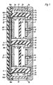
- 1 to 3 1 guide grooves 1 a to 1 c are made in a lens housing made of zinc injection molding, in which one piece of plastic, for. B. polymethylene methacrylate (PMMA), sprayed raster lens strips 2 to 4 are inserted.
- the strips 2 and 4 form the imaging strips in a known manner, while the strip 3 represents a field lens strip arranged in the intermediate image plane of the imaging system.
- the lens strips each carry two rows of lenses 2a, 2b or 3a, 3b or 4a, 4b, which, as can be seen from FIG. 1, are each offset both in the running direction A of the original and the recording medium and also transversely thereto.
- all three lens strips 2-4 are each made in one piece from an injection mold and inserted into the housing 1 in the same orientation.
- the field lens strip 3 could also be formed by two of said lens strips, which together have approximately half the focal length or double refractive power of the individual lens strip.
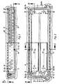
- centering lugs 2c, 3c and 4c are attached, each of which engages in recesses 1d of the lens housing 1.
- the respective lens strip 2 to 4 the guide groove such. B. can be seen from Fig. 2, the lens strip leaves a certain margin against longitudinal displacement, in the direction of its longitudinal extent in the lens housing 1.
- the recesses 1d are arranged in a plane for all lens strips, which is at a certain, albeit relatively small, distance e1 from the plane of symmetry of the housing 1 parallel to the direction of movement A of the original and the recording medium.
- the lens strips 2, 3 and 4 each have a flanged edge 2e, 2f or 3e, 3f or 4e, 4f on the back, by means of which a diaphragm strip 5 punched from strip-shaped hard PVC , 6 and 7 is recorded.
- the aperture strips 5 and 7 have circular openings 5a and 7a and form the Aperture diaphragms to limit the effective opening of the lens elements 2a, 2b or 4a, 4b.
- the openings 6a of the diaphragm strip 6 serve as intermediate image diaphragms to limit the image field of the intermediate images.
- these openings are designed as square openings with the direction of movement A parallel diagonal and dimensioned such that the opening parts one behind the other in the running direction each add to the total length of this diagonal. In this way, a uniform exposure of the record carrier passing under the system is ensured.
- honeycomb screens 8 and 9 are arranged between the lens strips, which, as can be seen from FIG. 3, each have a plastic, e.g. B. acrylonitrile-butadiene-styrene copolymer (ABS) molded honeycomb body 10 are formed, the honeycomb openings are covered on both sides by a metal strip 11 and 12, respectively.
- the cover strips 11 and 12 are connected to one another and to the panel body 10 by means of a screw bolt 33.
- guide projections 10a and 11a are formed at the ends of the cover strips 11 and 12, which engage in recesses 1e of the housing 1.
- the axis of symmetry of these guide lugs is offset by the amount e2 with respect to the axes of symmetry of the honeycomb panels 8 and 9, so that these honeycomb panels, on the underside of which fixing pins 13 engaging in each housing bore 1f, are inserted into the housing in only one orientation can be.
- Both the honeycomb panels 8 and 9 and the lens strips 2, 3 and 4 are after insertion into the housing by means of a plastic, for. B. polycarbonate (PC), manufactured cover 14 held in place.
- the cover is fastened to the housing 1 by means of screws 15 and presses on the upper edges of the lens strips and honeycomb panels with the interposition of elastic foam strips 36.
- strip-like extensions 16a and 16b are formed, each of which encompasses the upper edge of a cover glass 17 cemented into a recess 1g of the housing 1 and thereby, in the manner of a labyrinth seal, the penetration of dust and moisture into the cover glass edge Prevent the inside of the housing.
- brackets 21 for holding lugs 1k attached to the device housing 1 are fastened to a device board 18 by means of screws 19 and 20, respectively.
- the bolts 19 and 20 are riveted into a connecting piece 23 and inserted through bores 18a and 18b of the circuit board 18 and elongated holes 21 and 21b of the holding piece 21.
- Fastening nuts 23 and 24 are screwed onto the bolts 19 and 20, which clamp the holding piece 21 on the circuit board 18 with the interposition of washers 25 and 26.
- An eccentric 27 is also inserted between the washer 26 and the holding piece 21, which carries an adjustment slot 27a.
- the eccentric 27 mounted on the screw bolt 19 is mounted with its outer circumference in an annular flange 21c of the holding piece 21.
- the holding piece 21 guided on the elongated holes 21a and 21b can be adjusted in the direction of the arrow B-C.
- the housing 1 After insertion into the device, the housing 1 is held by means of the detent springs 22, which engage in detent recesses 1i of the holding lugs 1k k of the lens housing 1.
- the detent springs 22 are articulated on the device side to a pin 28 which is fastened to the holding piece 21.
Landscapes
- Physics & Mathematics (AREA)
- Optics & Photonics (AREA)
- General Physics & Mathematics (AREA)
- Lens Barrels (AREA)
- Lenses (AREA)
- Facsimile Heads (AREA)
- Exposure Or Original Feeding In Electrophotography (AREA)
- Optical Systems Of Projection Type Copiers (AREA)
Applications Claiming Priority (2)
| Application Number | Priority Date | Filing Date | Title |
|---|---|---|---|
| DE2905740 | 1979-02-15 | ||
| DE2905740A DE2905740C2 (de) | 1979-02-15 | 1979-02-15 | Belichtungseinrichtung für Kopiergeräte |
Publications (2)
| Publication Number | Publication Date |
|---|---|
| EP0016934A1 EP0016934A1 (de) | 1980-10-15 |
| EP0016934B1 true EP0016934B1 (de) | 1982-11-17 |
Family
ID=6062966
Family Applications (1)
| Application Number | Title | Priority Date | Filing Date |
|---|---|---|---|
| EP80100575A Expired EP0016934B1 (de) | 1979-02-15 | 1980-02-05 | Belichtungseinrichtung für Kopiergeräte |
Country Status (4)
| Country | Link |
|---|---|
| US (1) | US4417809A (enExample) |
| EP (1) | EP0016934B1 (enExample) |
| JP (1) | JPS55123946U (enExample) |
| DE (1) | DE2905740C2 (enExample) |
Families Citing this family (4)
| Publication number | Priority date | Publication date | Assignee | Title |
|---|---|---|---|---|
| JPS5788113U (enExample) * | 1980-11-20 | 1982-05-31 | ||
| US4474459A (en) * | 1982-01-20 | 1984-10-02 | Minolta Camera Kabushiki Kaisha | Optical projection system |
| US4588287A (en) * | 1985-05-14 | 1986-05-13 | Xerox Corporation | Full-frame illumination and imaging system |
| DE3918293A1 (de) * | 1989-06-05 | 1990-12-06 | Zeiss Carl Fa | Linsenraster |
Family Cites Families (7)
| Publication number | Priority date | Publication date | Assignee | Title |
|---|---|---|---|---|
| US1984004A (en) * | 1929-01-18 | 1934-12-11 | Wildhaber Ernest | Means for presenting pictures |
| DE1260178B (de) * | 1964-11-20 | 1968-02-01 | Agfa Gevaert Ag | Fotografische Kamera mit einem rasterartigen Abbildungssystem |
| DE1203115B (de) * | 1964-11-20 | 1965-10-14 | Agfa Gevaert Ag | Belichtungsanordnung fuer Kopiergeraete |
| CH460381A (de) * | 1966-07-29 | 1968-07-31 | Rank Xerox Ltd | Optisches Abbildungssystem |
| US3584950A (en) * | 1967-11-17 | 1971-06-15 | Xerox Corp | Lens strip optical scanning system |
| US3687545A (en) * | 1969-03-28 | 1972-08-29 | Xerox Corp | Short focal length optical imaging system |
| DE2421661C2 (de) * | 1974-05-04 | 1982-05-13 | Agfa-Gevaert Ag, 5090 Leverkusen | Elektrostatisches Kopiergerät |
-
1979
- 1979-02-15 DE DE2905740A patent/DE2905740C2/de not_active Expired
-
1980
- 1980-02-05 EP EP80100575A patent/EP0016934B1/de not_active Expired
- 1980-02-13 JP JP1980016106U patent/JPS55123946U/ja active Pending
-
1982
- 1982-02-12 US US06/348,453 patent/US4417809A/en not_active Expired - Fee Related
Also Published As
| Publication number | Publication date |
|---|---|
| DE2905740C2 (de) | 1982-05-06 |
| JPS55123946U (enExample) | 1980-09-03 |
| DE2905740A1 (de) | 1980-08-21 |
| EP0016934A1 (de) | 1980-10-15 |
| US4417809A (en) | 1983-11-29 |
Similar Documents
| Publication | Publication Date | Title |
|---|---|---|
| DE69314955T2 (de) | Anordnung einer bildwandlereinheit. | |
| DE602005002868T2 (de) | Kraftfahrzeugrahmenanordnung | |
| DE1952128C3 (de) | Verfahren zur Herstellung eines Farbteilers | |
| DE69719691T2 (de) | Befestigung für Aussenhautteile einer Fahrzeugkarosserie | |
| DE202020006058U1 (de) | Kamerahalterung und elektronisches Gerät | |
| EP0016934B1 (de) | Belichtungseinrichtung für Kopiergeräte | |
| DE4001745A1 (de) | Vorrichtung zum ausrichten der optischen achse in einer tv-kamera | |
| DE102007010465A1 (de) | Lüfterbaugruppe sowie Befestigungsanordnung für selbige | |
| EP0980304B1 (de) | Tauchkantenwerkzeug | |
| DE69434092T2 (de) | System für optische bank | |
| DE2953695C1 (de) | Abbildungssystem fuer Kopiergeraete | |
| DE2953695C2 (enExample) | ||
| DE19727786C2 (de) | Verfahren und Werkzeug zum Spritzgießen von Gegenständen | |
| DE2939646C2 (de) | Meßinstrumentengehäuse | |
| DE2547648B2 (de) | Frontabdeckung fuer die schallwand eines lautsprechergehaeuses | |
| DE3146026A1 (de) | Abbildungseinrichtung | |
| DE10316926B3 (de) | Halterung für optische Elemente sowie Verfahren zur Herstellung | |
| DE2143820A1 (de) | Projektionsapparat für Mehrfachbildträger | |
| EP0502300A1 (de) | Distanzgeber | |
| DE2110318A1 (de) | Selbsttragende Mosaik-Schalttafel | |
| DE2904411A1 (de) | Gehaeuseteil eines mess-, steuer- oder regelgeraetes mit ansaetzen zur befestigung an einer platte | |
| DE202024104481U1 (de) | Wechselrahmen | |
| DE102024122692A1 (de) | Wechselrahmen | |
| DE102017203377A1 (de) | Montagehilfe für einen Führungswagen | |
| DE102016106189A1 (de) | Anzeigegerät |
Legal Events
| Date | Code | Title | Description |
|---|---|---|---|
| PUAI | Public reference made under article 153(3) epc to a published international application that has entered the european phase |
Free format text: ORIGINAL CODE: 0009012 |
|
| AK | Designated contracting states |
Designated state(s): BE CH FR GB NL |
|
| 17P | Request for examination filed |
Effective date: 19801103 |
|
| GRAA | (expected) grant |
Free format text: ORIGINAL CODE: 0009210 |
|
| AK | Designated contracting states |
Designated state(s): BE CH FR GB NL |
|
| ET | Fr: translation filed | ||
| PGFP | Annual fee paid to national office [announced via postgrant information from national office to epo] |
Ref country code: NL Payment date: 19840119 Year of fee payment: 5 |
|
| PGFP | Annual fee paid to national office [announced via postgrant information from national office to epo] |
Ref country code: CH Payment date: 19840202 Year of fee payment: 5 |
|
| PGFP | Annual fee paid to national office [announced via postgrant information from national office to epo] |
Ref country code: FR Payment date: 19840206 Year of fee payment: 5 |
|
| PGFP | Annual fee paid to national office [announced via postgrant information from national office to epo] |
Ref country code: BE Payment date: 19840331 Year of fee payment: 5 |
|
| PG25 | Lapsed in a contracting state [announced via postgrant information from national office to epo] |
Ref country code: CH Effective date: 19850228 Ref country code: BE Effective date: 19850228 |
|
| BERE | Be: lapsed |
Owner name: AGFA-GEVAERT A.G. Effective date: 19850205 |
|
| PG25 | Lapsed in a contracting state [announced via postgrant information from national office to epo] |
Ref country code: NL Effective date: 19850901 |
|
| GBPC | Gb: european patent ceased through non-payment of renewal fee | ||
| NLV4 | Nl: lapsed or anulled due to non-payment of the annual fee | ||
| PG25 | Lapsed in a contracting state [announced via postgrant information from national office to epo] |
Ref country code: FR Free format text: LAPSE BECAUSE OF NON-PAYMENT OF DUE FEES Effective date: 19851031 |
|
| REG | Reference to a national code |
Ref country code: CH Ref legal event code: PL |
|
| REG | Reference to a national code |
Ref country code: FR Ref legal event code: ST |
|
| PG25 | Lapsed in a contracting state [announced via postgrant information from national office to epo] |
Ref country code: GB Effective date: 19881118 |
|
| PLBE | No opposition filed within time limit |
Free format text: ORIGINAL CODE: 0009261 |
|
| STAA | Information on the status of an ep patent application or granted ep patent |
Free format text: STATUS: NO OPPOSITION FILED WITHIN TIME LIMIT |