EP0016436B1 - Servo-valve - Google Patents
Servo-valve Download PDFInfo
- Publication number
- EP0016436B1 EP0016436B1 EP80101350A EP80101350A EP0016436B1 EP 0016436 B1 EP0016436 B1 EP 0016436B1 EP 80101350 A EP80101350 A EP 80101350A EP 80101350 A EP80101350 A EP 80101350A EP 0016436 B1 EP0016436 B1 EP 0016436B1
- Authority
- EP
- European Patent Office
- Prior art keywords
- plunger
- pressure
- spool
- hydraulic
- servo
- Prior art date
- Legal status (The legal status is an assumption and is not a legal conclusion. Google has not performed a legal analysis and makes no representation as to the accuracy of the status listed.)
- Expired
Links
- 230000000694 effects Effects 0.000 claims description 5
- 230000010355 oscillation Effects 0.000 claims description 2
- 230000009699 differential effect Effects 0.000 description 3
- 238000006073 displacement reaction Methods 0.000 description 3
- 230000001105 regulatory effect Effects 0.000 description 3
- 238000010586 diagram Methods 0.000 description 2
- 230000005540 biological transmission Effects 0.000 description 1
- 230000001419 dependent effect Effects 0.000 description 1
- 230000005284 excitation Effects 0.000 description 1
- 238000005259 measurement Methods 0.000 description 1
Images
Classifications
-
- F—MECHANICAL ENGINEERING; LIGHTING; HEATING; WEAPONS; BLASTING
- F16—ENGINEERING ELEMENTS AND UNITS; GENERAL MEASURES FOR PRODUCING AND MAINTAINING EFFECTIVE FUNCTIONING OF MACHINES OR INSTALLATIONS; THERMAL INSULATION IN GENERAL
- F16K—VALVES; TAPS; COCKS; ACTUATING-FLOATS; DEVICES FOR VENTING OR AERATING
- F16K31/00—Actuating devices; Operating means; Releasing devices
- F16K31/02—Actuating devices; Operating means; Releasing devices electric; magnetic
- F16K31/06—Actuating devices; Operating means; Releasing devices electric; magnetic using a magnet, e.g. diaphragm valves, cutting off by means of a liquid
- F16K31/0686—Braking, pressure equilibration, shock absorbing
- F16K31/0693—Pressure equilibration of the armature
-
- F—MECHANICAL ENGINEERING; LIGHTING; HEATING; WEAPONS; BLASTING
- F15—FLUID-PRESSURE ACTUATORS; HYDRAULICS OR PNEUMATICS IN GENERAL
- F15B—SYSTEMS ACTING BY MEANS OF FLUIDS IN GENERAL; FLUID-PRESSURE ACTUATORS, e.g. SERVOMOTORS; DETAILS OF FLUID-PRESSURE SYSTEMS, NOT OTHERWISE PROVIDED FOR
- F15B13/00—Details of servomotor systems ; Valves for servomotor systems
- F15B13/02—Fluid distribution or supply devices characterised by their adaptation to the control of servomotors
- F15B13/04—Fluid distribution or supply devices characterised by their adaptation to the control of servomotors for use with a single servomotor
- F15B13/0401—Valve members; Fluid interconnections therefor
- F15B13/0402—Valve members; Fluid interconnections therefor for linearly sliding valves, e.g. spool valves
-
- F—MECHANICAL ENGINEERING; LIGHTING; HEATING; WEAPONS; BLASTING
- F15—FLUID-PRESSURE ACTUATORS; HYDRAULICS OR PNEUMATICS IN GENERAL
- F15B—SYSTEMS ACTING BY MEANS OF FLUIDS IN GENERAL; FLUID-PRESSURE ACTUATORS, e.g. SERVOMOTORS; DETAILS OF FLUID-PRESSURE SYSTEMS, NOT OTHERWISE PROVIDED FOR
- F15B13/00—Details of servomotor systems ; Valves for servomotor systems
- F15B13/02—Fluid distribution or supply devices characterised by their adaptation to the control of servomotors
- F15B13/04—Fluid distribution or supply devices characterised by their adaptation to the control of servomotors for use with a single servomotor
- F15B13/0401—Valve members; Fluid interconnections therefor
- F15B13/0407—Means for damping the valve member movement
-
- F—MECHANICAL ENGINEERING; LIGHTING; HEATING; WEAPONS; BLASTING
- F15—FLUID-PRESSURE ACTUATORS; HYDRAULICS OR PNEUMATICS IN GENERAL
- F15B—SYSTEMS ACTING BY MEANS OF FLUIDS IN GENERAL; FLUID-PRESSURE ACTUATORS, e.g. SERVOMOTORS; DETAILS OF FLUID-PRESSURE SYSTEMS, NOT OTHERWISE PROVIDED FOR
- F15B13/00—Details of servomotor systems ; Valves for servomotor systems
- F15B13/02—Fluid distribution or supply devices characterised by their adaptation to the control of servomotors
- F15B13/04—Fluid distribution or supply devices characterised by their adaptation to the control of servomotors for use with a single servomotor
- F15B13/044—Fluid distribution or supply devices characterised by their adaptation to the control of servomotors for use with a single servomotor operated by electrically-controlled means, e.g. solenoids, torque-motors
- F15B13/0442—Fluid distribution or supply devices characterised by their adaptation to the control of servomotors for use with a single servomotor operated by electrically-controlled means, e.g. solenoids, torque-motors with proportional solenoid allowing stable intermediate positions
-
- F—MECHANICAL ENGINEERING; LIGHTING; HEATING; WEAPONS; BLASTING
- F16—ENGINEERING ELEMENTS AND UNITS; GENERAL MEASURES FOR PRODUCING AND MAINTAINING EFFECTIVE FUNCTIONING OF MACHINES OR INSTALLATIONS; THERMAL INSULATION IN GENERAL
- F16K—VALVES; TAPS; COCKS; ACTUATING-FLOATS; DEVICES FOR VENTING OR AERATING
- F16K31/00—Actuating devices; Operating means; Releasing devices
- F16K31/02—Actuating devices; Operating means; Releasing devices electric; magnetic
- F16K31/06—Actuating devices; Operating means; Releasing devices electric; magnetic using a magnet, e.g. diaphragm valves, cutting off by means of a liquid
- F16K31/0603—Multiple-way valves
- F16K31/061—Sliding valves
- F16K31/0613—Sliding valves with cylindrical slides
-
- G—PHYSICS
- G05—CONTROLLING; REGULATING
- G05D—SYSTEMS FOR CONTROLLING OR REGULATING NON-ELECTRIC VARIABLES
- G05D16/00—Control of fluid pressure
- G05D16/20—Control of fluid pressure characterised by the use of electric means
- G05D16/2006—Control of fluid pressure characterised by the use of electric means with direct action of electric energy on controlling means
- G05D16/2013—Control of fluid pressure characterised by the use of electric means with direct action of electric energy on controlling means using throttling means as controlling means
- G05D16/2024—Control of fluid pressure characterised by the use of electric means with direct action of electric energy on controlling means using throttling means as controlling means the throttling means being a multiple-way valve
-
- Y—GENERAL TAGGING OF NEW TECHNOLOGICAL DEVELOPMENTS; GENERAL TAGGING OF CROSS-SECTIONAL TECHNOLOGIES SPANNING OVER SEVERAL SECTIONS OF THE IPC; TECHNICAL SUBJECTS COVERED BY FORMER USPC CROSS-REFERENCE ART COLLECTIONS [XRACs] AND DIGESTS
- Y10—TECHNICAL SUBJECTS COVERED BY FORMER USPC
- Y10T—TECHNICAL SUBJECTS COVERED BY FORMER US CLASSIFICATION
- Y10T137/00—Fluid handling
- Y10T137/8593—Systems
- Y10T137/86493—Multi-way valve unit
- Y10T137/86574—Supply and exhaust
- Y10T137/86622—Motor-operated
Definitions
- the invention relates to electromagnetically controlled hydraulic servo valves intended to provide hydraulic distribution as well as regulating the inlet and drain pressure of a hydraulic cylinder. It can also be used to regulate an automatic transmission line pressure.
- Such servo-valves are particularly used in the automatic control of clutches of motor vehicles, as well as in the control of clutches and brakes of automatic gearboxes.
- servo-valves are already known which are generally constituted by a first stage, mainly comprising a pallet closing off a nozzle, and a second stage with hydraulic slide driven by the first stage.
- Another type of servo valve is also known in which the displacements of a hydraulic slide are controlled by electrical measurements serving to control in position, by electronic means, a slide controlled by an electromagnet.
- FR-A-1173269 describes a device in which the two opposite ends of the slide and the plunger are placed respectively in end chambers connected to the distributed hydraulic pressure.
- the drawer and the plunger are in contact with each other. Contact between the drawer and the plunger takes place inside a pressure chamber. No differential hydraulic effect results from the application of the pressure distributed at the opposite ends of the drawer and the plunger.
- the object of the invention is to eliminate the above drawbacks, that is to say to produce a simple and space-saving device which, using a single drawer, ensures both the distribution and the pressure regulation and without the need for a position sensor or electronic servo device.
- the hydraulic servo-valve according to the invention comprising a distributor slide controlled by a plunger electromagnet placed along the same axis, the slide and the plunger being simply in contact with each other and the two opposite ends of the both of which are placed respectively in end chambers connected to the distributed hydraulic pressure, is characterized in that the contact between the plunger and the slide takes place inside a chamber without pressure and that the section of the plunger opening into the corresponding end chamber is slightly different from the section of the drawer opening into the corresponding end chamber, in a direction such that the differential hydraulic effect which results from the application of the distributed pressure produce a displacement of the drawer in the direction of a reduction of this distributed pressure.
- the invention consists in using a dispenser drawer actuated by a plunger electromagnet and in using the pressure distributed to hydraulically push the drawer and the plunger towards each other with throttles to dampen the oscillations.
- a feedback loop of the pressure distributed on the position of the drawer is produced, and in addition using a plunger of the polarized type supplied by a current which can pass. from negative to positive values, the capacity of the regulation is doubled.
- the electromagnet can be supplied by a pulsed or alternating current with continuous component.
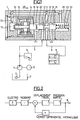
- the servo valve 1 is supplied by a conventional hydraulic circuit comprising a tank 2, a strainer 3, a pump 4 with a drive motor 5 and a pressure relief valve 6 on the pipe 7 bringing the hydraulic pressure to the servo valve 1
- the pressure distributed and regulated by the servo-valve 1 leaves it by the line 8 which supplies a jack 9, which controls for example a clutch or a brake.
- the single hydraulic slide 10 is of the conventional type with a central groove which moves between three annular spaces 11, 12 and 13 of the block of the servo-valve, the space 11 being joined to the pipe 7 for the arrival of the pressure, the space 12 at the pipeline 8 for distribution to the jack 9 and the space 13 at the discharge to the tank 2.
- the plunger electromagnet 14 comprises a movable assembly 15 whose axis is in line with the axis of drawer 10, with an end of axis 16 which opens into a chamber 17, and another end of axis 18 which opens into a second chamber 19 into which also opens the end 20 of drawer 10, the latter comprising - even another end 21 which opens into a third chamber 22 which contains a return spring 23.
- the chambers 17 and 22 are joined by hydraulic conduits visible in FIG. 1 to the chamber 12 from which the distributed pressure leaves, and the chamber 19 is joined to the downward discharge 2. From this way, the hydraulic thrusts which arise on the slide 10 and on the movable element 15 of the plunger have the effect of constantly pushing these two elements into contact with one another under all circumstances.
- the section of the ends of the axes 16 and 18 is chosen to be slightly different, for example, in the example chosen, greater than the section of the drawer 10, so that the distributed pressure applied to the chambers 17 and 22 produce a differential effect in the direction of reducing the distributed pressure, that is to say in the case of FIG. 1 by moving the slide 10 to the right in the direction of the arrow 26 against the spring 23.
- any movement of the movable assembly in the positive direction that is to say in the direction of the arrow 26, produces a reduction in the pressure at 8, therefore by reduction of the effect differential an imbalance in the negative direction opposing the disruptive displacement.
- any movement in the negative direction corresponds the birth of a positive restoring force opposing the disturbing movement.
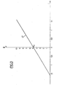
- the loop therefore acts well in the direction of regulation and the outlet pressure at 8, stabilized by this feedback loop, is on the other hand under the direct and proportional dependence of the force supplied by the electro- magnet.
- electro-plunger 14 a polarized electromagnet such as that described in French patent 2,311,394 in the name of the applicant as well as in its first certificate of addition no. 2,319,184. Indeed, this arrangement makes it possible to cover the remainder of the regulation line 27 below the point Po by reversing the direction of the current I in the electro 14.
- the receiving member that is to say the jack 9
- receives thanks to the device according to the invention, a filling and emptying pressure modulated with precision as a function of the electro-supply current 14.
Landscapes
- Engineering & Computer Science (AREA)
- General Engineering & Computer Science (AREA)
- Physics & Mathematics (AREA)
- Fluid Mechanics (AREA)
- Mechanical Engineering (AREA)
- General Physics & Mathematics (AREA)
- Automation & Control Theory (AREA)
- Servomotors (AREA)
- Magnetically Actuated Valves (AREA)
- Hydraulic Clutches, Magnetic Clutches, Fluid Clutches, And Fluid Joints (AREA)
Applications Claiming Priority (2)
| Application Number | Priority Date | Filing Date | Title |
|---|---|---|---|
| FR7907577A FR2452647A1 (fr) | 1979-03-26 | 1979-03-26 | Servo-valve |
| FR7907577 | 1979-03-26 |
Publications (3)
| Publication Number | Publication Date |
|---|---|
| EP0016436A2 EP0016436A2 (fr) | 1980-10-01 |
| EP0016436A3 EP0016436A3 (en) | 1981-03-25 |
| EP0016436B1 true EP0016436B1 (fr) | 1983-06-22 |
Family
ID=9223580
Family Applications (1)
| Application Number | Title | Priority Date | Filing Date |
|---|---|---|---|
| EP80101350A Expired EP0016436B1 (fr) | 1979-03-26 | 1980-03-14 | Servo-valve |
Country Status (10)
| Country | Link |
|---|---|
| US (1) | US4316599A (enExample) |
| EP (1) | EP0016436B1 (enExample) |
| JP (1) | JPS55132403A (enExample) |
| AR (1) | AR220971A1 (enExample) |
| BR (1) | BR8001776A (enExample) |
| CA (1) | CA1136516A (enExample) |
| DE (1) | DE3063822D1 (enExample) |
| ES (1) | ES489888A1 (enExample) |
| FR (1) | FR2452647A1 (enExample) |
| PT (1) | PT71014A (enExample) |
Families Citing this family (55)
| Publication number | Priority date | Publication date | Assignee | Title |
|---|---|---|---|---|
| DE3114437C2 (de) * | 1981-04-09 | 1989-10-12 | Mannesmann Rexroth GmbH, 8770 Lohr | Druckregelventil |
| DE3125143A1 (de) * | 1981-06-26 | 1983-01-13 | Mannesmann Rexroth GmbH, 8770 Lohr | "druckminderventil" |
| US4444216A (en) * | 1982-01-15 | 1984-04-24 | Koomey, Inc. | Pressure reducing and regulating valve |
| DE3207393C1 (de) * | 1982-03-02 | 1983-10-13 | Daimler-Benz Ag, 7000 Stuttgart | Steuerventil,insbesondere elektrohydraulisches Steuerventil |
| DE3225003A1 (de) * | 1982-07-03 | 1984-01-05 | Robert Bosch Gmbh, 7000 Stuttgart | Elektromagnetisch betaetigtes, proportional arbeitendes wegeventil |
| US4538645A (en) * | 1983-08-16 | 1985-09-03 | Ambac Industries, Inc. | Control valve assembly |
| USRE32644E (en) * | 1984-02-13 | 1988-04-12 | Robert W. Brundage | Solenoid controlled flow valve |
| DE3406794A1 (de) * | 1984-02-24 | 1985-09-05 | Mannesmann Rexroth GmbH, 8770 Lohr | Druckregelventil |
| US4649803A (en) * | 1984-08-15 | 1987-03-17 | The Garrett Corporation | Servo system method and apparatus, servo valve apparatus therefor and method of making same |
| US4662605A (en) * | 1985-01-30 | 1987-05-05 | G. W. Lisk Company, Inc. | Spool drive for pressure regulating, proportional solenoid valve |
| DE3505377C2 (de) * | 1985-02-16 | 1994-07-07 | Bosch Gmbh Robert | Druckregler |
| JPH0660700B2 (ja) * | 1985-04-01 | 1994-08-10 | 株式会社日立製作所 | 油圧制御用閉ル−プ式比例電磁弁 |
| DE3534692A1 (de) * | 1985-09-28 | 1987-04-16 | Hansa Metallwerke Ag | Steuerscheibenventil, insbesondere fuer den sanitaerbereich |
| US4838313A (en) * | 1987-05-28 | 1989-06-13 | Aisin Aw Co., Ltd. | Solenoid-operated pressure control valve |
| JPH0615286Y2 (ja) * | 1987-10-08 | 1994-04-20 | 日産自動車株式会社 | 比例減圧弁 |
| JP2696518B2 (ja) * | 1988-01-07 | 1998-01-14 | 本田技研工業株式会社 | 制動油圧制御装置 |
| JPH0544626Y2 (enExample) * | 1988-05-25 | 1993-11-12 | ||
| US5271430A (en) * | 1988-08-16 | 1993-12-21 | Kabushiki Kaisha Komatsu Seisakusho | Flow rate control valve device and flow force reduction structure |
| GB8821724D0 (en) * | 1988-09-16 | 1988-10-19 | Fairey Hydraulics | Direct drive valve |
| US5259414A (en) * | 1988-11-09 | 1993-11-09 | Aisin Aw Co., Ltd | Pressure control valve |
| JPH02129483A (ja) * | 1988-11-09 | 1990-05-17 | Aisin Aw Co Ltd | 圧力調整弁 |
| JPH02129476A (ja) * | 1988-11-09 | 1990-05-17 | Aisin Aw Co Ltd | 圧力調整弁 |
| EP0369412B1 (en) * | 1988-11-14 | 1996-09-11 | Sumitomo Electric Industries, Ltd. | Fluid pressure controller |
| JPH0724711Y2 (ja) * | 1988-12-27 | 1995-06-05 | 株式会社小松製作所 | 電気式油圧比例制御弁 |
| US4947893A (en) * | 1989-02-28 | 1990-08-14 | Lectron Products, Inc. | Variable force solenoid pressure regulator for electronic transmission controller |
| US4919012A (en) * | 1989-03-01 | 1990-04-24 | Ford Motor Company | Pilot operated solenoid valve in an automatic transmission control circuit |
| FR2650362A1 (fr) * | 1989-07-28 | 1991-02-01 | Theobald Sa A | Electrovanne de modulation du debit d'un fluide sous pression et ses applications |
| US5067687A (en) * | 1990-02-08 | 1991-11-26 | Applied Power Inc. | Proportional pressure control valve |
| US5076537A (en) * | 1990-07-19 | 1991-12-31 | Evc, Inc. | Electromechanical servovalve |
| JPH04325359A (ja) * | 1991-04-24 | 1992-11-13 | Nissan Motor Co Ltd | ブレーキアクチュエータ |
| US5249603A (en) * | 1992-05-19 | 1993-10-05 | Caterpillar Inc. | Proportional electro-hydraulic pressure control device |
| FR2715484B1 (fr) * | 1994-01-21 | 1996-02-23 | Chateaudun Hydraulique | Servovalve de régulation de pression. |
| AUPM806794A0 (en) * | 1994-09-12 | 1994-10-06 | First Green Park Pty Ltd | Improved lightweight load bearing base and packaging system for use therewith |
| US5579807A (en) * | 1994-09-14 | 1996-12-03 | Tec Tran Corporation | Solenoid-operated pressure control valve |
| JP3633166B2 (ja) * | 1996-12-28 | 2005-03-30 | アイシン・エィ・ダブリュ株式会社 | リニアソレノイド |
| US5778932A (en) * | 1997-06-04 | 1998-07-14 | Vickers, Incorporated | Electrohydraulic proportional pressure reducing-relieving valve |
| US5878766A (en) * | 1997-10-20 | 1999-03-09 | Vickers, Incorporated | Pressure compensated flow control valve |
| US5918635A (en) * | 1997-10-08 | 1999-07-06 | Vickers, Incorporated | Low pressure solenoid valve |
| US5984259A (en) * | 1997-11-26 | 1999-11-16 | Saturn Electronics & Engineering, Inc. | Proportional variable force solenoid control valve with armature damping |
| GB9820620D0 (en) * | 1998-09-23 | 1998-11-18 | Lucas Ind Plc | Improved solenoid controlled valve |
| US6435213B2 (en) * | 1999-04-23 | 2002-08-20 | Visteon Global Technologies, Inc. | Solenoid operated hydraulic control valve |
| DE19953209A1 (de) | 1999-11-05 | 2001-06-13 | Fluidtech Gmbh | Ventil, insbesondere Druckregelventil |
| JP2005282754A (ja) * | 2004-03-30 | 2005-10-13 | Toyoda Mach Works Ltd | 電磁弁 |
| KR100621983B1 (ko) * | 2004-07-23 | 2006-09-14 | 볼보 컨스트럭션 이키프먼트 홀딩 스웨덴 에이비 | 중장비용 가변 재생밸브 |
| CN100513848C (zh) * | 2004-08-12 | 2009-07-15 | 哈格雷夫斯技术公司 | 电磁阀及螺线管 |
| DE102005006321A1 (de) * | 2005-02-11 | 2006-08-17 | Hydac Fluidtechnik Gmbh | Ventil, insbesondere Proportinal-Druckbegrenzungsventil |
| DE102006007157A1 (de) * | 2005-07-20 | 2007-01-25 | Continental Teves Ag & Co. Ohg | Elektrisch ansteuerbares Ventil |
| US7353927B2 (en) * | 2005-09-28 | 2008-04-08 | Dana Automotive Systems Group, Llc. | Electro-magnetic actuator for torque coupling with variable pressure-control spool valve |
| US8991428B2 (en) * | 2009-03-30 | 2015-03-31 | Borgwarner Inc. | Die cast sleeve with stability enhancement features occupying a small package space |
| DE102011110257B3 (de) | 2011-06-06 | 2012-07-26 | Hydac Fluidtechnik Gmbh | Ventil, insbesondere Druckregelventil oderDruckbegrenzungsventil |
| DE102013014558A1 (de) * | 2013-08-31 | 2015-03-05 | Hydac Fluidtechnik Gmbh | Ventil nebst seiner Verwendung für eine Kupplung |
| FI126989B (fi) | 2015-03-16 | 2017-09-15 | Metso Flow Control Oy | Virtaavan aineen venttiilikokoonpano, prosessiventtiilin asennoitin sekä virtaavan aineen venttiilikokoonpanon käyttö prosessiventtiilin ohjauksessa |
| FI128617B (en) | 2016-03-30 | 2020-08-31 | Metso Flow Control Oy | Valve arrangement for fluid, adjuster for a process valve and use of a valve arrangement for fluid when controlling a process valve |
| US11408447B2 (en) * | 2018-06-11 | 2022-08-09 | Transgo, Llc | Methods and systems for improving the operation of transmissions for motor vehicles |
| US12085099B1 (en) * | 2020-06-18 | 2024-09-10 | Vacuworx Global, LLC | Flow control block for use with a vacuum material handler |
Family Cites Families (11)
| Publication number | Priority date | Publication date | Assignee | Title |
|---|---|---|---|---|
| DE1025693B (de) * | 1953-04-02 | 1958-03-06 | Erich Herion | Elektromagnetisch gesteuertes Dreiwege-Ventil mit Entlastungsmitteln |
| FR1173269A (fr) * | 1956-05-22 | 1959-02-23 | Soupape de commande équilibrée | |
| FR1201343A (fr) * | 1958-08-18 | 1959-12-29 | Soupape magnétique, notamment pour avions | |
| US3095906A (en) * | 1959-03-05 | 1963-07-02 | Moog Servocontrols Inc | Flow control servo valve with dynamic load pressure feedback |
| FR2059947B1 (enExample) * | 1969-06-10 | 1973-12-21 | Inst Avtom | |
| US3699271A (en) * | 1970-11-16 | 1972-10-17 | Bell Telephone Labor Inc | Speech processor using multiband controlled center clipping |
| US3958495A (en) * | 1972-08-31 | 1976-05-25 | Koehring Company | Air-oil amplifier |
| DE2262247A1 (de) * | 1972-12-20 | 1974-06-27 | Teves Gmbh Alfred | Elektromagnetisches ventil |
| FR2311394A1 (fr) * | 1975-05-16 | 1976-12-10 | Renault | Actuateur electromagnetique, notamment pour valve de servo-commande hydraulique |
| DE2621272C2 (de) * | 1975-05-16 | 1982-11-11 | Regie Nationale Des Usines Renault, 92109 Boulogne-Billancourt, Hauts-De-Seine | Elektromagnetische Betätigungsvorrichtung |
| CH624751A5 (en) * | 1977-03-22 | 1981-08-14 | Wandfluh Ag | Five-chamber directional control valve with damping of reversal shocks |
-
1979
- 1979-03-26 FR FR7907577A patent/FR2452647A1/fr active Granted
-
1980
- 1980-03-14 DE DE8080101350T patent/DE3063822D1/de not_active Expired
- 1980-03-14 EP EP80101350A patent/EP0016436B1/fr not_active Expired
- 1980-03-24 US US06/133,079 patent/US4316599A/en not_active Expired - Lifetime
- 1980-03-25 CA CA000348357A patent/CA1136516A/fr not_active Expired
- 1980-03-25 ES ES489888A patent/ES489888A1/es not_active Expired
- 1980-03-25 AR AR28043780A patent/AR220971A1/es active
- 1980-03-25 BR BR8001776A patent/BR8001776A/pt unknown
- 1980-03-26 PT PT71014A patent/PT71014A/pt unknown
- 1980-03-26 JP JP3764280A patent/JPS55132403A/ja active Pending
Also Published As
| Publication number | Publication date |
|---|---|
| EP0016436A2 (fr) | 1980-10-01 |
| PT71014A (en) | 1980-04-01 |
| BR8001776A (pt) | 1980-11-18 |
| EP0016436A3 (en) | 1981-03-25 |
| ES489888A1 (es) | 1980-10-01 |
| US4316599A (en) | 1982-02-23 |
| JPS55132403A (en) | 1980-10-15 |
| DE3063822D1 (en) | 1983-07-28 |
| AR220971A1 (es) | 1980-12-15 |
| CA1136516A (fr) | 1982-11-30 |
| FR2452647B1 (enExample) | 1983-02-25 |
| FR2452647A1 (fr) | 1980-10-24 |
Similar Documents
| Publication | Publication Date | Title |
|---|---|---|
| EP0016436B1 (fr) | Servo-valve | |
| US4345489A (en) | Hydraulic control system for servos in automatic transmissions | |
| US4091690A (en) | Method for controlling continuously variable drive ratio transmissions and a system therefor | |
| FR2570036A1 (fr) | Dispositif de secours pour un systeme de commande electronique de transmission automatique | |
| FR2487742A1 (fr) | Systeme de transmission de couple | |
| US5944626A (en) | Emergency hydraulic control with control valves for continuously variable transmission | |
| EP0194927B1 (fr) | Dispositif asservi de contrôle de pression pour installation hydraulique, notamment pour direction assistée de véhicule | |
| FR2467129A1 (fr) | Circuit hydraulique pour vehicule a commande hydraulique | |
| WO2012093240A1 (fr) | Dispositif de régulation de pression avec détection de la position neutre | |
| EP0493992B1 (fr) | Actionneur pour la commande d'un embrayage à friction doté d'un diaphragme, notamment pour véhicule automobile | |
| EP2980417B1 (fr) | Servovalve à ensemble mobile double | |
| FR2717260A1 (fr) | Dispositif pour déterminer la position d'un élément de réglage. | |
| US5421294A (en) | Hydraulic setting device | |
| EP0534971A1 (en) | Control system for a continuously variable cone pulley-drive belt transmission | |
| EP0750241B1 (fr) | Régulateur hydraulique de débit | |
| FR2471524A1 (fr) | Dispositif hydrodynamique pour transmettre un couple mecanique, et notamment frein hydrodynamique | |
| US7270224B2 (en) | Device for the optimization of hydraulically controlled engagement of clutches used in marine transmissions | |
| EP1750026B1 (fr) | Dispositif d'assistance pour la commande hydraulique d'un embrayage, notamment d'un véhicule automobile | |
| US4760867A (en) | Pressure modulator valve device | |
| JPH05280629A (ja) | 円錐形プーリ式無段変速機 | |
| FR2540193A1 (fr) | Appareil hydraulique de division et de sommation d'ecoulements pour deux ou plusieurs appareils de consommation | |
| US4487304A (en) | Control system for a fluid pressure engaged clutch | |
| JPH0440031Y2 (enExample) | ||
| FR2578919A1 (fr) | Dispositif asservi de controle de debit pour installation hydraulique, notamment pour direction assistee de vehicule | |
| GB2101256A (en) | Control system for a fluid pressure engaged clutch |
Legal Events
| Date | Code | Title | Description |
|---|---|---|---|
| PUAI | Public reference made under article 153(3) epc to a published international application that has entered the european phase |
Free format text: ORIGINAL CODE: 0009012 |
|
| AK | Designated contracting states |
Designated state(s): BE DE GB IT NL SE |
|
| PUAL | Search report despatched |
Free format text: ORIGINAL CODE: 0009013 |
|
| AK | Designated contracting states |
Designated state(s): BE DE GB IT NL SE |
|
| 17P | Request for examination filed |
Effective date: 19810525 |
|
| ITF | It: translation for a ep patent filed | ||
| GRAA | (expected) grant |
Free format text: ORIGINAL CODE: 0009210 |
|
| AK | Designated contracting states |
Designated state(s): BE DE GB IT NL SE |
|
| REF | Corresponds to: |
Ref document number: 3063822 Country of ref document: DE Date of ref document: 19830728 |
|
| PGFP | Annual fee paid to national office [announced via postgrant information from national office to epo] |
Ref country code: DE Payment date: 19831221 Year of fee payment: 5 |
|
| PGFP | Annual fee paid to national office [announced via postgrant information from national office to epo] |
Ref country code: SE Payment date: 19840331 Year of fee payment: 5 |
|
| PLBE | No opposition filed within time limit |
Free format text: ORIGINAL CODE: 0009261 |
|
| STAA | Information on the status of an ep patent application or granted ep patent |
Free format text: STATUS: NO OPPOSITION FILED WITHIN TIME LIMIT |
|
| 26N | No opposition filed | ||
| PGFP | Annual fee paid to national office [announced via postgrant information from national office to epo] |
Ref country code: BE Payment date: 19841231 Year of fee payment: 6 |
|
| PGFP | Annual fee paid to national office [announced via postgrant information from national office to epo] |
Ref country code: NL Payment date: 19870331 Year of fee payment: 8 |
|
| PG25 | Lapsed in a contracting state [announced via postgrant information from national office to epo] |
Ref country code: GB Effective date: 19890314 |
|
| PG25 | Lapsed in a contracting state [announced via postgrant information from national office to epo] |
Ref country code: SE Effective date: 19890315 |
|
| PG25 | Lapsed in a contracting state [announced via postgrant information from national office to epo] |
Ref country code: BE Effective date: 19890331 |
|
| BERE | Be: lapsed |
Owner name: REGIE NATIONALE DES USINES RENAULT Effective date: 19890331 |
|
| PG25 | Lapsed in a contracting state [announced via postgrant information from national office to epo] |
Ref country code: NL Effective date: 19891001 |
|
| GBPC | Gb: european patent ceased through non-payment of renewal fee | ||
| NLV4 | Nl: lapsed or anulled due to non-payment of the annual fee | ||
| PG25 | Lapsed in a contracting state [announced via postgrant information from national office to epo] |
Ref country code: DE Effective date: 19891201 |
|
| EUG | Se: european patent has lapsed |
Ref document number: 80101350.9 Effective date: 19900118 |