EP0015770A1 - Stereophonic sound synthesizer - Google Patents
Stereophonic sound synthesizer Download PDFInfo
- Publication number
- EP0015770A1 EP0015770A1 EP80300723A EP80300723A EP0015770A1 EP 0015770 A1 EP0015770 A1 EP 0015770A1 EP 80300723 A EP80300723 A EP 80300723A EP 80300723 A EP80300723 A EP 80300723A EP 0015770 A1 EP0015770 A1 EP 0015770A1
- Authority
- EP
- European Patent Office
- Prior art keywords
- signal
- frequency
- stereo
- frequencies
- sound
- Prior art date
- Legal status (The legal status is an assumption and is not a legal conclusion. Google has not performed a legal analysis and makes no representation as to the accuracy of the status listed.)
- Ceased
Links
Images


Classifications
-
- H—ELECTRICITY
- H04—ELECTRIC COMMUNICATION TECHNIQUE
- H04S—STEREOPHONIC SYSTEMS
- H04S5/00—Pseudo-stereo systems, e.g. in which additional channel signals are derived from monophonic signals by means of phase shifting, time delay or reverberation
Definitions
- This invention relates to a system which synthesizes stereophonic sound by developing two separate sound channels from a single monophonic sound source in general and, in particular, to the employment of such a synthetic stereophonic sound system in combination with a visual display such as a television receiver.
- the indirect sounds due to the recording room acoustics are not lost. This is because the two microphones are each recording direct sounds which arrive by different sound paths. Thus, the direct sounds of one microphone will have their reflected or indirect sounds recorded by the other microphone. Since the direct sounds at the latter microphone differ from those of the former, only minimal masking will occur.
- the orchestra does not appear to emanate from a "hole-in-the- wall", but instead appears to be distributed throughout and behind the plane of the two loudspeakers.
- the two-channel recording results in the reproduction of a sound field which enables a listener to both locate individual instruments and to sense the acoustical character of the recording room or concert hall.
- the synthetic stereophonic effect arises due to an intensity -vs- frequency as well as an intensity -vs- time difference in the indirect signal pattern set up at the two ears. This gives the impression that different frequency components arrive from different directions due to room reflection echoes, giving the reproduced sound a more natural, diffused quality.
- True stereophony is characterized by two distinct qualities which distinguish it from single- channel reproduction.
- the first of these is directional separation of sound sources and the second is the sensation of "depth” and "presence” that it creates.
- the sensation of separation has been described as that which gives the listener the ability to judge the selective location of various sound sources, such as the position of the instruments in an orchestra.
- the sensation of presence is the feeling that the sounds seem to emerge, not from the reproducing loudspeakers themselves, but from positions in between and usually somewhat behind the loudspeakers. The latter sensation gives the listener an impression of the size, acoustical character, and depth of the recording location.
- Two-channel stereophonic sound reproduction preserves both qualities of directional separation and ambience. Synthesized stereophonic sound reproduction, however, does not attempt to recreate stereo directionality, but only the sensation of depth and presence that is a characteristic of true two-channel stereophony. However, some directionality is necessarily introduced, since sounds of certain frequencies will be reproduced fully in one channel and sharply attenuated in the other as a result of either phase or amplitude modulation of the signals of the two channels.
- the two qualities of directional separation and ambience create an impression in the mind of the viewer listener that he is a part of the scene.
- the sensation of ambience will recreate the acoustical properties of the recording studio or location, and the directional sensation will make various sounds appear to emanate from their respective locations in the visual image.
- the presence sensation produces the feeling that sounds are coming from positions behind the plane of the loudspeakers, a certain three-dimensional effect is also produced.
- a synthesized stereophonic sound reproduction system in combination with a visual medium will produce a somewhat similar effect to that which is realized with two-channel stereo.
- a sensation of ambience will be created in the mind of the viewer.
- the ambience sensation produced by synthesized stereo is better suited to the visual medium than that produced by two-channel stereo. This is because, as Lochner and Keet discovered, the apparent width of the sound field created by two-channel stereo is generally greater than that created by synthesized stereo.
- the two-channel stereo sound field can in fact appear to be wider than the visual image being viewed, with certain sounds coming from beyond the limits of the image.
- the synthesized stereo system achieves its intended effect by controlling the relative amplitudes and/or phases of the sound signals as a function of the audible frequency spectrum at the reproducing loudspeakers.
- a television viewer is watching and listening to a scene including a speaker with a bass voice on the left side of the viewing area, and a speaker with a soprano voice on the right side.
- Two reproducing loudspeakers are located to the left and right of the image, evenly spaced from the center of the image.
- a stereophonic sound synthesizer which develops two complementary spectral intensity modulated signals from a single monaural signal.
- the monaural signal is applied as the input signal for a transfer function circuit of the form H(s), which modulates the intensity of the monaural signal as a function of frequency.
- the intensity modulated H(s) signal is coupled to a reproducing loudspeaker, and comprises one channel of the synthetic stereo system.
- the H(s) signal is also coupled to one input of a differential amplifier.
- the monaural signal is coupled to the other input of the differential amplifier to produce a difference signal which is the complement of the H(s) signal.
- the difference signal is coupled to a second reproducing loudspeaker, which comprises the second channel of the synthetic stereo system.
- a stereo synthesizer is utilized as the sound reproducing system of a television receiver, with the reproducing loudspeakers located on either side of the kinescope.
- the H(s) transfer function circuit is comprised of two twin-tee notch filters, which produce notches of reduced signal level at 150 Hz and 4600 Hz.
- the output signal produced by the differential amplifier has signal level peaks at these notch frequencies, and a complementary notch at the H(s) signal peak at 700 Hz.
- the H(s) channel signal and the difference channel signal are in a substantially constant 90 degree phase relationship, which provides a sound field which is distributed between, but does not appear to be distributed beyond, the space between the two loudspeakers.
- the amplitude -vs- frequency response curves of the two output channels have crossover points, at which the amplitudes of the two response curves are equal, which effectively centers sounds at these frequencies between the loudspeakers.
- the notch frequencies are chosen such that two of these crossover points occur at approximately the frequency of peak intensity of the human voice, and at the center frequency of the second(articulation) formant frequencies of the human voice, respectively, so as to effectively center voices on the kinescope while preserving the ambience effect of other, more randomly distributed sound signals. Centering the second formant frequencies also provides increased quality in the reproduction of speech sounds.
- a monaural sound signal M originating from a source having a typical response curve shown at A of the FIGURE is coupled from an input terminal 10 to a transfer function circuit 20 and to the positive input of a differential amplifier 40.
- the transfer function is expressed as H(s), where (s) represents a complex variable in Laplace transform notation.
- the output of the transfer function circuit 20 is coupled to the negative input of the differential amplifier 40.
- the transfer function H(s) has a characteristic amplitude response which varies with frequency. This results in modulation of the intensity of the M signal over its frequency spectrum.
- the frequency response of the transfer function circuit 20 is sharply attenuated at certain frequencies, and relatively unattenuated (or amplified) at other frequencies.
- the H(s) output signal will therefore lack certain portions of the total input spectrum of the monaural signal M due to this spectral intensity modulation.
- the output signal H(s) comprises one channel of the stereo synthesizer, and a typical response curve of the H(s) channel is shown at B of FIGURE 1.
- the second channel of the stereo synthesizer is produced by subtracting the output signal of the transfer function circuit 20 from the original monaural signal M in the differential amplifier 40.
- the signal produced at the output of the differential amplifier 40, M-H(s) is the complement of the H(s) channel, since it contains those components of the monaural signal M which the H(s) signal lacks.
- a typical response curve of the M-H(s) channel is shown at C of FIGURE 1.
- the two channels H(s) and M-H(s) together comprise the entire sound spectrum of the original monaural signal M. This may be determined by adding the signals from the two channels: Thus, the entire sound spectrum of the original monaural signal.M is preserved in the two channels. However, the sound field has an increased ambience due to the varying distribution of the sound field between the two channels. The intensities of different frequency sound signals are reproduced in varying ratios in the two channels due to the spectral intensity modulation of the H(s) transfer function.
- a stereo synthesizer constructed in accordance with the principles of the present invention is shown in schematic detail in FIGURE 2.
- a monaural sound signal is applied to an input terminal 100.
- the monaural signal is coupled to the input of the H(s) transfer function circuit 20 by a resistor 102.
- the transfer function circuit 20 is comprised of two cascaded twin-tee notch filters 200 and 220.
- the circuit providing the H(s) function may be implemented in a variety of ways not fully described in this application.
- circuits providing the H(s) transfer function have been constructed using parallel transistorized bandpass filters and cascaded transistorized bandstop filters.
- the use of the twin-tee notch filters shown in FIGURE 2 is advantageous in that, by impedance scaling the circuit, the need for transistors or other active circuit components is eliminated from the transfer function circuit.
- the first twin-tee notch filter 200 of the cascaded pair exhibits a characteristic response with a sharp attenuation, or notch, at a predetermined frequency, in this example, 150 Hz.
- the filter 200 is comprised of a first path including two series coupled capacitors, 202 and 206, between its input and output.
- a resistor 204 is coupled from the junction of the capacitors 202 and 206 to a source of reference potential (ground).
- the filter 200 also includes a second signal path in parallel with the first, comprising two series coupled resistors 208 and 212.'
- a capacitor 210 is coupled from the junction of the resistors 208 and 212 to ground.
- the capacitor 202 and the resistor 204 act as a differentiator which provides a phase lead to input signals supplied by resistor 102.
- the resistor 208 and capacitor 210 act as an integrator, which provides a phase lag to input signals in that signal path.
- the signal supplied by capacitor 206 leads the signal supplied by resistor 212 by.180 degrees, and since the signals were identical in amplitude and phase at the input, two 150 Hz signals will cancel at the junction of capacitor 206 and resistor 212. This cancellation produces the characteristic notch in the response curve of the twin-tee filter.
- the second twin-tee notch filter 220 is constructed in a manner similar to filter 200.
- a first signal path is coupled from the output of filter 200 to the output of the H(s) transfer function circuit 20, comprising two series coupled capacitors 222 and 226.
- a resistor 224 is coupled from the junction of the capacitors 222 and 226 to ground.
- a second path, comprised of series coupled resistors 228 and 232, is coupled in parallel with the first path.
- a capacitor 230 is coupled from the junction of resistors 228 and 232 to ground.
- This second notch filter 220 operates in a similar fashion to notch filter 200 and produces a characteristic notch at 4600 Hz in this example.
- the component values of the second notch filter 220 are greater than those used in the first notch filter 200 to avoid loading the first filter 200.
- the signal produced by the transfer function circuit 20 is coupled to the non-inverting (+) inputs of two differential power amplifiers 40 and 42 by a coupling capacitor 112.
- a filter capacitor 114 is coupled from the two positive power amplifier inputs to ground.
- the differential power amplifier 40 is used to generate a difference signal from the H(s) transfer function signal.and the monaural signal.
- the power amplifier 42 having the same non-inverting input impedance and the same output impedance as the amplifier 40, is used to match the impedance of the H(s) signal channel to that of the H(s)-M channel.
- the non-inverting input impedances are preferably substantially greater than the output impedance of the transfer function circuit 20.
- the inverting (-) input of power amplifier 42 is coupled to ground by the serial connection of a resistor 122 and a capacitor 120.
- a feedback resistor 124 is coupled from the output of the power amplfier 42 to the negative input.
- the ratio of the feedback resistor 124 to the negative input resistor 122 determines the gain of the power amplifier 42. In the example shown in FIGURE 2, the gains of the two power amplfiers 40 and 42 are approximately equal.
- the power amplifier 42 drives a load comprising the serial connection of a resistor 126 and a capacitor 128 from the output of the power amplfier to ground.
- the H(s) signal at the output of the power amplifier is coupled to a switch terminal 152 by a capacitor 130.
- the monaural sound signal at the input terminal 100 is coupled to the parallel combination of a resistor 1 0 4 and a potentiometer 106 by the resistor 102. The opposite end of this parallel combination is coupled to ground.
- the wiper arm of the potentiometer 106 is coupled to the inverting input of power amplifier 40 by the serial connection of a capacitor 108 and a resistor 110.
- a feedback resistor 132 is coupled from the output of the power amplifier 40 to the inverting input terminal.
- the power amplifier 40 drives a load comprised of the serial connection of a resistor 134 and a capacitor 136 which is coupled from the output of the power amplifier 40 to ground.
- the difference signal developed at the output of the power amplifier 40, H(s)-M is coupled to a switch terminal 158 by a capacitor 140.
- Switch 150 is a double pole, double throw switch used to select either monophonic reproduction or synthetic stereo reproduction.
- the monaural sound signal at the input terminal. 100 is coupled to switch terminals 156 and 162.
- Blade 154 is coupled to a first loudspeaker 170
- bladel60 is coupled to a second loudspeaker 172.
- the H(s) signal at switch terminal 152 is coupled to loudspeaker 170 by blade 154
- the H(s)-M signal at switch terminal 158 is coupled to loudspeaker 172 by blade 160.
- the loudspeakers will reproduce a synthetic stereo sound field when switch 150 is in this position.
- the monaural signal at switch terminals 156 and 162 is coupled to the loudspeakers for the generation of a monophonic sound field.
- the potentiometer 106 provides a means for adjusting the depths of the notches in the H(s)-M signal developed by the differential amplifier 40.
- the monaural sound signal which is supplied to the differential amplifier 40 is attenuated by the potentiometer in an amount determined by the setting of the wiper arm of the potentiometer, In this way, the amplitude of the M signal which is subtracted from the H (s) signal by the differential amplifier 40 is controlled.
- the potentiometer is usually set to provide an M signal with an amplitude equal to that of the H(s) signal at the 700 Hz notch frequency of the H(s)-M signal.
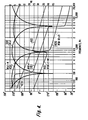
- the depths of the H(s)-M signal notches, and the frequencies at which they are located, are also determined by the phase of the H(s) signal. This is illustrated by the response curves of the circuit of FIGURE 2, which are shown in FIGURE 4.
- the intensity, or amplitude, of the H(s) signal channel produced by the cascaded twin-tee notch filters 200 and 220 is illustrated as a function of frequency by response curve 300.
- This response curve 300 is seen to have its characteristic notches located at 150 Hz and 4600 Hz.
- the complementary response curve 400 of the H(s)-M signal channel is seen to have a notch at approximately 700 HZ, at which frequency the amplitude of the H(s) response curve 300 is at a maximum.
- the location of the notches in the audio frequency spectrum is of particular significance when the stereo sound synthesizer is used in conjunction with a visual image, such as a television receiver. This is because sounds at the notch frequencies have a distinct directional characteristic, as sounds at these frequencies are fully reproduced in one loudspeaker and fully attenuated in the other. Moreover, it follows that sounds at the crossover points of the amplitude vs frequency response curves 300 and 400 will be reproduced with equal intensity in both channels, thereby locating these sounds at a point intermediate the two loudspeakers. Thus, since the location of the notches concomitantly locates the crossover points in the audio frequency spectrum, the notch locations are critical in the determination of those frequencies at which sounds will appear to be centered with respect to the two loudspeakers.
- the H(s) signal prefferably in phase with the M signal when the response curve 300 of the H(s) signal is at a maximum in order to produce a truly complementary H(s)-M response of maximum notch depth.
- the phase of the M signal is taken as the reference phase in FIGURE 4, and is assumed to be 0° throughout the frequency spectrum of the monaural signal M.
- the phase response of the H(s) signal is represented by curve 310, and is seen to be approximately 0° when the amplitude of the H(s) response curve 300 is at a maximum at 700 Hz.
- the M signal is used as the reference amplitude in FIGURE 4, with a constant amplitude equal to the maximum amplitude of the H(s) signal, subtraction of the H(s) and M signals by the differential amplifier 40 results in virtually a complete cancellation of the H(s)-M signal at 700 Hz, and therefore a notch of maximum depth.
- the degree of mutual cancellation of the two signals by the differential amplifier 40 is controlled by the adjustment of the amplitude M signal by the potentiometer 106, as discussed above.
- the phase response curve 310 of the H(s) signal channel shows that the H(s) signal channel has a linearly decreasing phase angle relative to the M signal between the notch frequencies of 150 Hz and 4600 Hz. In the vicinity of these notch frequencies, the H(s) signal undergoes a 180° phase reversal.
- the H(s)-M signal channel is seen to have a similarly unique phase response curve 410 which behaves in a similar fashion.
- the phase response curves 310 and 410 of the two channels reveal that the two signals are in a substantially constant phase relationship of approximately 90° between the notch frequencies, and are momentarily either in phase or out of phase at the notch frequencies.
- the phase and amplitude response curves of FIGURE 4 indicate the manner in which the sounds produced by the two loudspeakers 170 and 172 develop the perceived ambience of the stereo synthesizer. Since the loudspeaker sound signals are in a substantially constant 90° phase relationship between the notch frequencies, they will neither additively combine (as they would if they were in phase) nor will they cancel each other (as they would if they were 180° out of phase) at the ears of the listener. Instead, the responses of the loudspeakers will be substantially as shown by the amplitude response curves 300 and 400, without a phase "tilt" which would tend to reinforce or cancel sound signals at certain frequencies.
- the perceived ambience effect is developed by the varying ratios of the sound signal amplitudes produced by the loudspeakers over the sound frequency spectrum.
- the phase relationship of the two output signals is of even less significance when the two loudspeakers are not widely separated, as is the case when they are located on either side of a television kinescope.
- phase differential of 90° between the two output signals will produce a distributed sound field which appears to just cover the space between the two loudspeakers.
- phase differentials less than 90° the distribution is narrower, and at phase angles in excess of 90° the sound field increases in dimension until it appears to cover the entire 180° plane of the two loudspeakers.
- This phenomenon is advantageous when the stereo synthesizer is used in cooperation with a visual medium which occupies the entire space between the loudspeakers, such as a movie screen or television kinescope, as the sound field will then appear to emanate from throughout the visual image, but not beyond its physical boundaries.
- the sound signals of the two channels are exactly in phase and out of phase at the notch frequencies, and thus would tend to reinforce or cancel each other at these frequencies.
- one sound signal is always fully attenuated at the notch frequencies, there is virtually no signal reinforcement or cancellation at the notch frequencies.
- the phase response curve 420 of the M-H(s) signal illustrates graphically a point that was previously demonstrated mathematically: that the reversal of the input polarities of the differential amplifier 40 to produce an M-H(s) signal instead of H(s)-M signal will result in the same synthetic stereo effect.
- the amplitude response curve 400 is the same for both difference channel signals, but the phases of the two signals are 180° apart.
- the M-H(s) phase response curve 420 shows that the M-H(s) signal and the H(s) signal are still related by approximately 90° between the notch frequencies, and are momentarily either in phase or out of phase at the notch frequencies.
- the two loudspeakers 170 and 172 produce sound signals which correspond to the amplitude response curves 300 and 400 of FIGURE 3, it may be appreciated that different frequency sounds will appear to come from different loudspeakers, or some point between the two. For instance, if the H(s) signal loudspeaker 170 is placed to the left of the listener and the H(s)-M loudspeaker 172 to the right, a 50 Hz tone will be reproduced primarily in the right loudspeaker, and a 700 Hz tone would come from the left loudspeaker.
- Tones between these two notch frequencies would appear to come from locations intermediate the left and right loudspeaker; and a 320 Hz tone would appear to come from a point halfway between the two loudspeakers, since such a tone will be reproduced with equal intensity in the two loudspeakers.
- the synthetic stereo system reproduces sound signals having a large number of different frequency components, such as music from a symphony orchestra or the voices of a large crowd, different frequency components will appear to come simultaneously from different directions, giving the listener a more realistic sensation of the ambience of the concert hall or crowd.
- the stereo synthesizer of the present invention may be used in conjunction with a visual medium, such as a television receiver, to create a more realistic audio and visual effect for the viewer.
- a television receiver 180 employing the stereo synthesizer of FIGURE 2 is shown in FIGURE 3.
- the television kinescope 182 should be centered between the two loudspeakers 170 and 172 which are located close to the sides of the kinescope, as illustrated in FIGURE 3, to prevent the sound field from appearing significantly larger than the scene being viewed. More importantly, the relative intensities of different frequency signals in the two sound channels must be carefully controlled through proper selection of the notch and crossover frequencies of the response curves 300 and 400 to avoid the confusing reversal of the directions of the sound and image to which reference was made previously.
- the transfer function filter notches should be arranged to properly locate the crossover points of equal intensity in the sound spectrum.
- the majority of television programming contains images of individuals who are talking or singing. Since the synthetic stereo system has no way of determining the relative locations of the images of the individuals, the system must not operate so as to reproduce human voices with a degree of directionality, to prevent possible reversal of the voice locations with respect to the images of the individuals.
- the synthetic stereo system should reproduce human voices with equal intensity in the two loudspeakers so that the voices will appear to emanate from the center of the picture. Sounds with little or no visual directional content, on the other hand, can be reproduced so as to appear to emanate from various locations in the television image.
- FIGURE 5 shows a comparison of the amplitude response curves 300 and 400 of the stereo synthesizer, and the average intensity vs. frequency response curve 500 of the human voice.
- curve 500 illustrates, the human voice has an average intensity which peaks around 350 Hz. Above this frequency, voice power drops off rapidly. Below the response curves are shown the frequency ranges of bass, tenor, alto and soprano singing voices.
- these frequency ranges are approximately centered about the crossover frequency of the stereo synthesizer, 320 Hz, at which the amplitudes of the signals produced by the two sound channels are equal, so as to produce a centered sound sensation.
- this 320 Hz crossover frequency is also very near the peak of the voice intensity response curve 500.
- the stereo synthesizer here shown will therefore produce a centering effect near the frequency at which the human voice is producing, on the average, the most voice power. This is accomplished by locating the first and second notches at 150 Hz and 700 Hz, respectively, to produce the desired crossover frequency at 320 Hz.
- the voiced sounds of speech are produced by forcing air from the lungs through the larynx, or voicebox.
- the larynx contains two folds of skin, or vocal cords, which are separated by an opening called the glottis.
- the vocal cords vibrate at a fundamental frequency having higher overtones or harmonics which define the pitch of the voiced sound.
- the amplitude of the vocal cord harmonics decrease with frequency at the rate of about 12 decibels per octave, as illustrated in FIGURE 6(a).
- the pitch of the vocal cord vibrations is changed during singing or talking by constricting or relaxing the muscles in the larynx which control the vocal cords.
- the sounds produced by the vocal cords pass through the pharynx and the mouth which, together with the larynx, comprise the vocal tract.
- the vocal tract from the larynx to the lips acts as a resonant cavity which attenuates certain frequencies to a lesser degree than others.
- the vocal tract has four or five important resonant frequencies called formant frequencies, or simply formants.
- formant frequencies may be shifted during speech by altering the position of the voice articulators: the lips, the jaw, the tongue and the larynx.
- a singer or trained public speaker will take advantage of these formant frequencies by altering his articulators so as to simultaneously shift his pitch frequency and a formant frequency into close proximity to produce a sound of greater relative amplitude, or loudness, without the need for increased air pressure from the lungs.
- Formants are labeled Fl, F2, F3, et cetera, in the order in which they appear in the frequency scale. The relative importance of the individual formants decreases with increasing order above F2, since the intensity of higher order formants decreases exponentially.
- the first formant Fl varies for male speakers over a range of 250 to 700 Hz and the distances between the formants on the frequency scale average 1000Hz.
- a typical formant pattern for a male is shown in FIGURE 6(b). Since the formant frequencies are a function of vocal tract dimensions, females have larger average formant spacings and higher average formant frequencies than males. Similar relations hold for children compared with adults.
- Fl and F2 are the main determinants of vowel quality, but it is the location of F2 with respect to Fl and F3 which determines the intelligibility of speech, a measure usually referred to as articulation. This is due to the fact that the vowel sounds which predominate in common speech have a higher energy content than consonants since they are "voiced", that is,they depend upon vocal cord vibrations for their production. By contrast, consonant sounds, which may be characterized in general as breaks in vowel sounds (i.e.
- /t/ and /p/ do not require vocal cord vibrations for their production (except for the vowel-like consonants /r/, /m/, /n/, /ng/ and /1/ and hence are produced with reduced loudness as compared with vowels.
- unvoiced consonants are 20 db weaker than vowel sounds. It has been found that the ability of a listener to discern the weaker consonant sounds is the prime determinant of the articulation measure of speech.
- consonants like vowels, have their own particular formant frequencies, it is not the formants of the consonants alone which govern articulation. Rather, the quality of a consonant is determined by its effect on the vowel or vowels with which it is associated, as characterized by its effect on the second formant of the vowel, called the "hub" of the speech sound.
- a consonant before or after a vowel causes the second formant of the vowel to proceed away from the hub or "locus" F2 of a preceding consonant or toward the hub of a succeeding consonant. It is this transistional behavior of the second formant of a vowel before or after a consonant which gives a vital clue to the identity of that consonant.
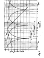
- FIGURE 7 illustrates that the location of the upper notch frequency at 4600 Hz, together with the location of the intermediate notch at 700 Hz, provide a crossover of equal loudspeaker signal amplitudes at approximately 1680 Hz. Below these loudspeaker channel response curves are plotted the locations of the first three formants for the ten most common vowel sounds.
- the formant frequencies shown are average values for men, women and children.
- the first formant values range from 270 Hz to 1050 Hz, with a mean value of 560 Hz, designated by arrow Fl.
- the response curves of the two loudspeaker channels show an intensity differential of approximately 12 db at this mean value
- the lower crossover frequency at 320 Hz is a compromise between the ranges of pitch frequencies of the human voice, the intensity distribution of the human voice, and the first formant frequencies. Since the pitch frequencies are generally lower than the first formant frequencies, ranging down to 90 Hz for bass voices, it is not surprising that the voice intensity curve 500 should peak at a frequency intermediate the average pitch and first formant frequencies.
- the lower crossover frequency of 320 Hz is satisfactory because it is closely related to the peak of the voice intensity response curve 500.
- FIGURE 7 shows second formant frequencies ranging from 850 Hz to 3200 Hz, and third formant frequencies varying from 1680 Hz to 3500 Hz.
- Second formant amplitudes are an average of 12 db below the average of first formants, and the third formants have an average amplitude which is over 26 db below that of the first formants.
- the mean frequencies for the second and third formants are represented by arrows F2 and F3, respectively. It is seen that the intensity levels of the two loudspeakers are approximately 5 db apart at the mean value of the third formant F3, and that the mean value of the important hub formant F2 is almost exactly at the equal intensity crossover point of the two loudspeaker channels.
- the second formant will, on the average, be produced with equal intensity by both loudspeakers.
- the voice sounds thereby reproduced will appear centered with respect to the television image, and will have an enhanced intelligibility, or articulation.
- the stereo synthesizer of the present invention will create the impression that the voices of the speakers are coming from the center of the television image.
- the background noises which are produced in the office environment are distributed fairly randomly over the sound spectrum, ranging from approximately 30 Hz to 16000 Hz. These background sounds will be reproduced by the loudspeakers in varying ratios in accordance with the response curves 300 and 400 of FIGURE 4, thereby creating a distinct ambience effect as the office sounds appear to emanate from throughout the televised image. Viewing pleasure is increased as the television viewer gains an increased sensation of being a part of the office scene, instead of merely being an outside observer.
Landscapes
- Physics & Mathematics (AREA)
- Engineering & Computer Science (AREA)
- Acoustics & Sound (AREA)
- Signal Processing (AREA)
- Stereophonic System (AREA)
Applications Claiming Priority (2)
| Application Number | Priority Date | Filing Date | Title |
|---|---|---|---|
| US06/018,905 US4239939A (en) | 1979-03-09 | 1979-03-09 | Stereophonic sound synthesizer |
| US18905 | 1979-03-09 |
Publications (1)
| Publication Number | Publication Date |
|---|---|
| EP0015770A1 true EP0015770A1 (en) | 1980-09-17 |
Family
ID=21790357
Family Applications (1)
| Application Number | Title | Priority Date | Filing Date |
|---|---|---|---|
| EP80300723A Ceased EP0015770A1 (en) | 1979-03-09 | 1980-03-07 | Stereophonic sound synthesizer |
Country Status (6)
| Country | Link |
|---|---|
| US (1) | US4239939A (ja) |
| EP (1) | EP0015770A1 (ja) |
| JP (1) | JPS55123300A (ja) |
| KR (1) | KR830000937B1 (ja) |
| CA (1) | CA1135839A (ja) |
| DK (1) | DK156361C (ja) |
Cited By (4)
| Publication number | Priority date | Publication date | Assignee | Title |
|---|---|---|---|---|
| EP0060097A1 (en) * | 1981-03-09 | 1982-09-15 | Rca Corporation | Split phase stereophonic sound synthesizer |
| FR2505534A1 (fr) * | 1981-05-08 | 1982-11-12 | Rca Corp | Agencement de commutation pour un synthetiseur stereophonique du son |
| US4479235A (en) * | 1981-05-08 | 1984-10-23 | Rca Corporation | Switching arrangement for a stereophonic sound synthesizer |
| WO2000022880A2 (en) * | 1998-10-13 | 2000-04-20 | Srs Labs, Inc. | Apparatus and method for synthesizing pseudo-stereophonic outputs from a monophonic input |
Families Citing this family (24)
| Publication number | Priority date | Publication date | Assignee | Title |
|---|---|---|---|---|
| US4449229A (en) * | 1980-10-24 | 1984-05-15 | Pioneer Electronic Corporation | Signal processing circuit |
| NL8320241A (nl) * | 1982-07-22 | 1984-06-01 | Tvi Systems Ltd | Monaurale- binaurale audioverwerkingsinrichting. |
| US4555795A (en) * | 1982-07-22 | 1985-11-26 | Tvi Systems, Ltd. | Monaural to binaural audio processor |
| US4517602A (en) * | 1982-10-18 | 1985-05-14 | Rca Corporation | Dynamic noise filter for an audio signal in a television |
| US4653096A (en) * | 1984-03-16 | 1987-03-24 | Nippon Gakki Seizo Kabushiki Kaisha | Device for forming a simulated stereophonic sound field |
| US4748669A (en) * | 1986-03-27 | 1988-05-31 | Hughes Aircraft Company | Stereo enhancement system |
| US4783814A (en) * | 1986-10-09 | 1988-11-08 | Comprehensive Health Care Corp. Of America | Stethoscope having pseudostereophonic binaural enhancement |
| US4739514A (en) * | 1986-12-22 | 1988-04-19 | Bose Corporation | Automatic dynamic equalizing |
| JP2610139B2 (ja) * | 1987-09-05 | 1997-05-14 | ヤマハ株式会社 | 楽音発生装置 |
| US4841572A (en) * | 1988-03-14 | 1989-06-20 | Hughes Aircraft Company | Stereo synthesizer |
| US5274708A (en) * | 1992-06-01 | 1993-12-28 | Fusan Labs, Inc. | Digital stereo sound enhancement unit and method |
| JP2886402B2 (ja) * | 1992-12-22 | 1999-04-26 | 株式会社河合楽器製作所 | ステレオ信号発生装置 |
| KR0120086Y1 (ko) * | 1993-08-31 | 1998-07-15 | 김광호 | 사운드 절환회로 |
| US5661808A (en) | 1995-04-27 | 1997-08-26 | Srs Labs, Inc. | Stereo enhancement system |
| US5692050A (en) * | 1995-06-15 | 1997-11-25 | Binaura Corporation | Method and apparatus for spatially enhancing stereo and monophonic signals |
| US7260231B1 (en) * | 1999-05-26 | 2007-08-21 | Donald Scott Wedge | Multi-channel audio panel |
| US7031474B1 (en) | 1999-10-04 | 2006-04-18 | Srs Labs, Inc. | Acoustic correction apparatus |
| US7277767B2 (en) | 1999-12-10 | 2007-10-02 | Srs Labs, Inc. | System and method for enhanced streaming audio |
| US7016509B1 (en) | 2000-09-08 | 2006-03-21 | Harman International Industries, Inc. | System and method for varying low audio frequencies inversely with audio signal level |
| US7522733B2 (en) * | 2003-12-12 | 2009-04-21 | Srs Labs, Inc. | Systems and methods of spatial image enhancement of a sound source |
| JP5063528B2 (ja) * | 2008-08-21 | 2012-10-31 | 株式会社オーディオテクニカ | ノイズキャンセルシステム |
| JP2014168228A (ja) * | 2013-01-30 | 2014-09-11 | Yamaha Corp | 放音装置 |
| WO2014190140A1 (en) | 2013-05-23 | 2014-11-27 | Alan Kraemer | Headphone audio enhancement system |
| FI20195726A1 (en) * | 2019-09-02 | 2021-03-03 | Genelec Oy | A system and method for producing complementary sound |
Citations (2)
| Publication number | Priority date | Publication date | Assignee | Title |
|---|---|---|---|---|
| DE944799C (de) * | 1954-10-23 | 1956-06-21 | Nordwestdeutscher Rundfunk | Anordnung fuer Einkanal-Stereophonie |
| US3670106A (en) * | 1970-04-06 | 1972-06-13 | Parasound Inc | Stereo synthesizer |
Family Cites Families (3)
| Publication number | Priority date | Publication date | Assignee | Title |
|---|---|---|---|---|
| US2616970A (en) * | 1948-02-11 | 1952-11-04 | Hartford Nat Bank & Trust Co | Device for the transmission by electrical means of oscillations of acoustic frequency |
| US3056854A (en) * | 1957-11-27 | 1962-10-02 | Unitronics Corp | Binaural sound system for television receivers |
| US4137510A (en) * | 1976-01-22 | 1979-01-30 | Victor Company Of Japan, Ltd. | Frequency band dividing filter |
-
1979
- 1979-03-09 US US06/018,905 patent/US4239939A/en not_active Expired - Lifetime
-
1980
- 1980-02-28 CA CA000346611A patent/CA1135839A/en not_active Expired
- 1980-03-05 JP JP2857180A patent/JPS55123300A/ja active Granted
- 1980-03-07 DK DK100380A patent/DK156361C/da not_active IP Right Cessation
- 1980-03-07 EP EP80300723A patent/EP0015770A1/en not_active Ceased
- 1980-03-08 KR KR1019800000965A patent/KR830000937B1/ko active
Patent Citations (2)
| Publication number | Priority date | Publication date | Assignee | Title |
|---|---|---|---|---|
| DE944799C (de) * | 1954-10-23 | 1956-06-21 | Nordwestdeutscher Rundfunk | Anordnung fuer Einkanal-Stereophonie |
| US3670106A (en) * | 1970-04-06 | 1972-06-13 | Parasound Inc | Stereo synthesizer |
Non-Patent Citations (2)
| Title |
|---|
| JOURNAL OF THE AUDIO ENGINEERING SOCIETY, Vol. 18, No. 2, April 1970, pages 157-164 New York, U.S.A. R. ORBAN: "A Rational Technique for Synthesizing Pseudo-Stereo from Monophonic Sources" * Page 158, left-hand column, line 20 - page 160, left-hand column, line 26; figures 1-4 * * |
| JOURNAL OF THE AUDIO ENGINEERING SOCIETY, Vol. 6, No. 2, April 1958 pages 74-79 New York, U.S.A. M.R. SCHROEDER: "An Artificial Stereophonic Effect Obtained from a Single Audio Signal" * Page 74, left-hand column, line 1 - page 78, line 9; figures 1-11 * * |
Cited By (7)
| Publication number | Priority date | Publication date | Assignee | Title |
|---|---|---|---|---|
| EP0060097A1 (en) * | 1981-03-09 | 1982-09-15 | Rca Corporation | Split phase stereophonic sound synthesizer |
| FR2505534A1 (fr) * | 1981-05-08 | 1982-11-12 | Rca Corp | Agencement de commutation pour un synthetiseur stereophonique du son |
| US4479235A (en) * | 1981-05-08 | 1984-10-23 | Rca Corporation | Switching arrangement for a stereophonic sound synthesizer |
| WO2000022880A2 (en) * | 1998-10-13 | 2000-04-20 | Srs Labs, Inc. | Apparatus and method for synthesizing pseudo-stereophonic outputs from a monophonic input |
| WO2000022880A3 (en) * | 1998-10-13 | 2000-08-03 | Srs Labs Inc | Apparatus and method for synthesizing pseudo-stereophonic outputs from a monophonic input |
| US6590983B1 (en) | 1998-10-13 | 2003-07-08 | Srs Labs, Inc. | Apparatus and method for synthesizing pseudo-stereophonic outputs from a monophonic input |
| JP2009141972A (ja) * | 1998-10-13 | 2009-06-25 | Srs Labs Inc | 擬似立体音響出力をモノラル入力から合成する装置および方法 |
Also Published As
| Publication number | Publication date |
|---|---|
| CA1135839A (en) | 1982-11-16 |
| KR830000937B1 (ko) | 1983-05-11 |
| JPS55123300A (en) | 1980-09-22 |
| DK156361C (da) | 1989-12-27 |
| DK156361B (da) | 1989-08-07 |
| US4239939A (en) | 1980-12-16 |
| JPH0136320B2 (ja) | 1989-07-31 |
| DK100380A (da) | 1980-09-10 |
Similar Documents
| Publication | Publication Date | Title |
|---|---|---|
| US4239939A (en) | Stereophonic sound synthesizer | |
| US6590983B1 (en) | Apparatus and method for synthesizing pseudo-stereophonic outputs from a monophonic input | |
| KR100433642B1 (ko) | 스테레오증강시스템 | |
| US8036767B2 (en) | System for extracting and changing the reverberant content of an audio input signal | |
| US8213622B2 (en) | Binaural sound localization using a formant-type cascade of resonators and anti-resonators | |
| US4356349A (en) | Acoustic image enhancing method and apparatus | |
| US8509454B2 (en) | Focusing on a portion of an audio scene for an audio signal | |
| Griesinger | General overview of spatial impression, envelopment, localization, and externalization | |
| US5043970A (en) | Sound system with source material and surround timbre response correction, specified front and surround loudspeaker directionality, and multi-loudspeaker surround | |
| US4706287A (en) | Stereo generator | |
| US4567607A (en) | Stereo image recovery | |
| US5119422A (en) | Optimal sonic separator and multi-channel forward imaging system | |
| Griesinger | Equalization and spatial equalization of dummy-head recordings for loudspeaker reproduction | |
| Jecklin | A different way to record classical music | |
| US4394535A (en) | Split phase stereophonic sound synthesizer | |
| US3940560A (en) | Quadriphonic sound pick-up and reproduction devices | |
| US3050583A (en) | Controllable stereophonic electroacoustic network | |
| De Man | Audio Effects in Sound Design | |
| Sigismondi | Personal monitor systems | |
| US5539833A (en) | Audio signal amplifier device | |
| Uhle | Center signal scaling using signal-to-downmix ratios | |
| EP0323830B1 (en) | Surround-sound system | |
| Olson et al. | On the realistic reproduction of sound with particular reference to sound motion pictures | |
| Woszczyk | A new method for spatial enhancement in stereo and surround recording | |
| Olson | The Objective and Subjective Aspects of Sound Reproduction |
Legal Events
| Date | Code | Title | Description |
|---|---|---|---|
| PUAI | Public reference made under article 153(3) epc to a published international application that has entered the european phase |
Free format text: ORIGINAL CODE: 0009012 |
|
| AK | Designated contracting states |
Designated state(s): AT DE FR GB IT |
|
| 17P | Request for examination filed |
Effective date: 19810224 |
|
| DET | De: translation of patent claims | ||
| RAP1 | Party data changed (applicant data changed or rights of an application transferred) |
Owner name: RCA CORPORATION |
|
| STAA | Information on the status of an ep patent application or granted ep patent |
Free format text: STATUS: THE APPLICATION HAS BEEN REFUSED |
|
| 18R | Application refused |
Effective date: 19860919 |
|
| RIN1 | Information on inventor provided before grant (corrected) |
Inventor name: GRIFFIS, PATRICK DOUGLAS |