EP0015207B1 - Vorrichtung zum Halten eines Werkstücks in einer gewissen Position zu einer Werkzeugmaschine, auf der es befestigt werden kann - Google Patents
Vorrichtung zum Halten eines Werkstücks in einer gewissen Position zu einer Werkzeugmaschine, auf der es befestigt werden kann Download PDFInfo
- Publication number
- EP0015207B1 EP0015207B1 EP80400237A EP80400237A EP0015207B1 EP 0015207 B1 EP0015207 B1 EP 0015207B1 EP 80400237 A EP80400237 A EP 80400237A EP 80400237 A EP80400237 A EP 80400237A EP 0015207 B1 EP0015207 B1 EP 0015207B1
- Authority
- EP
- European Patent Office
- Prior art keywords
- clamping screw
- jaw
- fixed
- movable
- fixed jaw
- Prior art date
- Legal status (The legal status is an assumption and is not a legal conclusion. Google has not performed a legal analysis and makes no representation as to the accuracy of the status listed.)
- Expired
Links
Images


Classifications
-
- B—PERFORMING OPERATIONS; TRANSPORTING
- B25—HAND TOOLS; PORTABLE POWER-DRIVEN TOOLS; MANIPULATORS
- B25B—TOOLS OR BENCH DEVICES NOT OTHERWISE PROVIDED FOR, FOR FASTENING, CONNECTING, DISENGAGING OR HOLDING
- B25B1/00—Vices
- B25B1/24—Details, e.g. jaws of special shape, slideways
- B25B1/2405—Construction of the jaws
- B25B1/2473—Construction of the jaws with pull-down action on the workpiece
-
- B—PERFORMING OPERATIONS; TRANSPORTING
- B23—MACHINE TOOLS; METAL-WORKING NOT OTHERWISE PROVIDED FOR
- B23Q—DETAILS, COMPONENTS, OR ACCESSORIES FOR MACHINE TOOLS, e.g. ARRANGEMENTS FOR COPYING OR CONTROLLING; MACHINE TOOLS IN GENERAL CHARACTERISED BY THE CONSTRUCTION OF PARTICULAR DETAILS OR COMPONENTS; COMBINATIONS OR ASSOCIATIONS OF METAL-WORKING MACHINES, NOT DIRECTED TO A PARTICULAR RESULT
- B23Q3/00—Devices holding, supporting, or positioning work or tools, of a kind normally removable from the machine
- B23Q3/02—Devices holding, supporting, or positioning work or tools, of a kind normally removable from the machine for mounting on a work-table, tool-slide, or analogous part
- B23Q3/06—Work-clamping means
- B23Q3/066—Bench vices
-
- B—PERFORMING OPERATIONS; TRANSPORTING
- B25—HAND TOOLS; PORTABLE POWER-DRIVEN TOOLS; MANIPULATORS
- B25B—TOOLS OR BENCH DEVICES NOT OTHERWISE PROVIDED FOR, FOR FASTENING, CONNECTING, DISENGAGING OR HOLDING
- B25B1/00—Vices
- B25B1/06—Arrangements for positively actuating jaws
- B25B1/10—Arrangements for positively actuating jaws using screws
- B25B1/103—Arrangements for positively actuating jaws using screws with one screw perpendicular to the jaw faces, e.g. a differential or telescopic screw
Definitions
- the devices intended to hold a workpiece in a determined position relative to a machine tool on which they can be fixed usually comprise a fixed jaw having two orthogonal reference surfaces, a movable jaw. perpendicular to one of these surfaces, and a clamping screw, also perpendicular to this surface, making it possible to clamp the workpiece between the fixed jaw and the movable jaw; they currently only respond very imperfectly to the goal sought; in fact, when they are subjected to a large clamping force, there is deflection of the body of the fixed jaw on which the movable jaw slides, and these deflections cause geometric defects in the position of the jaws; moreover, if they are subjected to a repetition of efforts, permanent deformations occur which make these same drawbacks permanent.
- this accounting structure is constituted by an elongated part having its two raised ends, one of which serves as support for the fixed jaw, the other of which is pierced with a tapped hole in which is engaged and is engaged the clamping screw of the movable jaw.
- the present invention relates to a device for maintaining a workpiece in a determined position relative to a machine tool to which it can be fixed, and whatever the tightening, comprising a fixed jaw having two reference surfaces orthogonal, a movable jaw perpendicular to one of these surfaces, and a clamping screw, also perpendicular to this surface, making it possible to clamp the workpiece between the fixed jaw and the movable jaw, and further comprising a structure intended to collect stress reactions exerted on the fixed and movable jaw, this structure having for this purpose a front part against which the fixed jaw bears and a rear part pierced with a tapped orifice, through which passes, and in which is engaged , the thread of the clamping screw of the movable jaw, said complementary structure being arranged so as to eliminate all of the above-mentioned drawbacks from those known to date.
- this structure is constituted by two flanges joined to each other, in their central part, by at least one tie rod parallel to the clamping screw and, at their lower part opposite to that where the screw is located. clamping, by at least one compression bar.
- the tie rod (s), parallel to the clamping screw collect all the tensile forces
- the compression bar (s), also parallel to the clamping screw collect with the tie rod (s) all the compression forces, without either of them being subjected to any bending force.
- the flanges their central part is subjected to the tension force due to the reaction of the tie rods, and their upper and lower parts to equal and symmetrical thrusts which balance out, due to the tightening screw for one, and the reaction of the compression bars for each other; they are short and massive pieces, which can be easily sized so that their deflection does not affect the effectiveness of the clamping.
- the tie rods and compression bars which are not subjected to any bending force, can be of small section, and the same applies to the orifices of the body of the fixed jaw, through which these tie rods and these bars pass freely; these orifices therefore do not weaken the body of the fixed jaw, which is not subjected to any bending force and which can therefore easily have the desired rigidity.
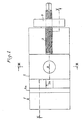
- the device shown conventionally comprises a body 1 of fixed jaw 1 a in which slides 1 b are arranged which guide the sliding of the mobile jaw 2 under the action of the tightening screw 3.
- the latter instead of being engaged with the tapping of an orifice provided in an ear of the body of the fixed jaw, is engaged and engaged with the tapping of an orifice provided in a flange 4, connected to a counter-flange 5 by tie rods 6 in their central part, and by compression bars 7 in their lower part.
- the fixed jaw 1 is supported on the convex part 5a of the counter-flange 5, provided in the axis of the clamping screw 3, and the compression bar on its other convex part 5b, symmetrical with the preceding with respect to the tie rod 6.
- the plane containing the drawbars 6 is located between the plane containing the compression bars 7 and the axis of the clamping screw 3. This plane is located midway between the plane containing the compression bars 7 and the axis of the tightening screw 3, without constituting an obligation.
- the tie rods 6 and compression bars 7 are subjected only to axial forces, and to no bending force, and the flanges 4 and 5 are separate parts, short and massive, subjected to forces.well balanced; all the deformations of this device cause during tightening a free axial sliding of the tie rods 6 and the compression bars 7; only the domed part 5a of the counter-flange 5, on which the body 1 of the fixed jaw 1a rests, remains in its initial position.
- the tie rods 6, which can be of small diameter since they are only subjected to tensile forces, freely pass through holes drilled for this purpose in the body 1 of the fixed jaw; the compression bars 7, subjected only to compression forces, also pass freely through holes drilled for this purpose in the body 1, but such that they avoid any possibility of buckling.
- a piston 8 is housed in a corresponding orifice of the movable jaw 2 and the yoke 9; it has a cross section in the form of an H allowing it to slide on the runners 1b of the body 1 of the fixed jaw; the end 8a of the piston 8 is inclined from bottom to top, from rear to front, and it bears on a face 10, of the same inclination, of the movable jaw 2.
- the mobile jaw 2 is applied against the upper guide faces of the sliding movement of the mobile jaw 2 on the body 1 of the fixed jaw, and then, by reaction, the piston 8 lifts the yoke 9 and therefore maintains its lower shoulder applied against the lower guide faces of the sliding of the movable jaw 2 on the body 1 of the fixed jaw.
- the inclined end of the clamping screw 3 is constituted by the yoke 11, also in the form of H, which differs from the yoke 9 in that it is constituted by an inclined cylinder, instead of being by a straight cylinder, like clevis 9; its rear face has a flat 11 a, on which bears the end of the clamping screw 3, and its inclined front face 11 b cooperates with a face 10 of the same inclination of the orifice of the movable jaw 2, in which this yoke 11 can slide freely, to produce the same result as the inclined face 8a of the piston 8 cooperating with the face 10 of the same inclination of the movable jaw 2 in the embodiment described above.
- the clamping screw 3 is engaged and engaged with a nut 12 mounted with ball joint in the flange 4.
- the flange 5 may be constituted by the rear part 13 of the body 1 of the fixed jaw 1 a, as also shown in FIG. 4; it is also subjected to the tension exerted by the tie rods 6, counterbalancing the thrusts exerted by the clamping screw 3 and the compression bars 7, as is the flange 5 of FIGS. 1 to 3.
Landscapes
- Engineering & Computer Science (AREA)
- Mechanical Engineering (AREA)
- Gripping Jigs, Holding Jigs, And Positioning Jigs (AREA)
- Jigs For Machine Tools (AREA)
- Clamps And Clips (AREA)
- Gripping On Spindles (AREA)
Claims (11)
Priority Applications (1)
| Application Number | Priority Date | Filing Date | Title |
|---|---|---|---|
| AT80400237T ATE1885T1 (de) | 1979-02-20 | 1980-02-19 | Vorrichtung zum halten eines werkstuecks in einer gewissen position zu einer werkzeugmaschine, auf der es befestigt werden kann. |
Applications Claiming Priority (2)
| Application Number | Priority Date | Filing Date | Title |
|---|---|---|---|
| FR7904613A FR2449511A1 (fr) | 1979-02-20 | 1979-02-20 | Support de piece pour usinage par machine-outil |
| FR7904613 | 1979-02-20 |
Publications (2)
| Publication Number | Publication Date |
|---|---|
| EP0015207A1 EP0015207A1 (de) | 1980-09-03 |
| EP0015207B1 true EP0015207B1 (de) | 1982-12-01 |
Family
ID=9222344
Family Applications (1)
| Application Number | Title | Priority Date | Filing Date |
|---|---|---|---|
| EP80400237A Expired EP0015207B1 (de) | 1979-02-20 | 1980-02-19 | Vorrichtung zum Halten eines Werkstücks in einer gewissen Position zu einer Werkzeugmaschine, auf der es befestigt werden kann |
Country Status (6)
| Country | Link |
|---|---|
| US (1) | US4295641A (de) |
| EP (1) | EP0015207B1 (de) |
| JP (1) | JPS55150948A (de) |
| AT (1) | ATE1885T1 (de) |
| DE (1) | DE3061176D1 (de) |
| FR (1) | FR2449511A1 (de) |
Families Citing this family (24)
| Publication number | Priority date | Publication date | Assignee | Title |
|---|---|---|---|---|
| US4345750A (en) * | 1981-02-02 | 1982-08-24 | Glaser Hans F | Vise |
| CH652059A5 (fr) * | 1983-04-22 | 1985-10-31 | Bobst Sa | Dispositif de centrage et de fixation d'un outil dans un support. |
| FR2559085B2 (fr) * | 1984-02-02 | 1987-06-26 | Boucher Freres Sarl Ets | Dispositif permettant de maintenir une piece a usiner dans une position determinee par rapport a une machine-outil sur laquelle ce dispositif peut etre fixe |
| US4569509A (en) * | 1984-04-02 | 1986-02-11 | Johann Good | Vise, particularly a machine vise |
| DE3532490A1 (de) * | 1985-09-12 | 1987-03-19 | Kesel Georg Gmbh & Co Kg | Spanngeraet |
| US4759535A (en) * | 1986-05-31 | 1988-07-26 | Tamotsu Takasugi | Machine vice |
| FR2613968A1 (fr) * | 1987-04-14 | 1988-10-21 | Perez Ets | Etau de serrage, notamment pour machines-outils |
| DE3841527C1 (de) * | 1988-12-09 | 1990-06-13 | Peter 7293 Pfalzgrafenweiler De Schuele | |
| DE3927197A1 (de) * | 1989-08-17 | 1991-02-21 | Sta Co Mettallerzeugnisse Gmbh | Spannvorrichtung |
| FR2689797B1 (fr) * | 1992-04-13 | 1994-07-22 | Evard Precision Sa | Etau autocentrant. |
| US5374041A (en) * | 1994-02-25 | 1994-12-20 | Kurt Manufacturing Company, Inc. | Vise |
| CA2471981C (en) * | 2003-06-23 | 2009-11-03 | Fablock Inc. | Precision vice |
| US8454004B1 (en) | 2006-09-01 | 2013-06-04 | Chick Workholding Solutions, Inc. | Workholding apparatus having a movable jaw member |
| US9227303B1 (en) | 2006-09-01 | 2016-01-05 | Chick Workholding Solutions, Inc. | Workholding apparatus |
| US8109494B1 (en) * | 2006-09-01 | 2012-02-07 | Chick Workholding Solutions, Inc. | Workholding apparatus having a movable jaw member |
| US8336867B1 (en) | 2006-09-01 | 2012-12-25 | Chick Workholding Solutions, Inc. | Workholding apparatus having a detachable jaw plate |
| US8573578B1 (en) | 2006-09-01 | 2013-11-05 | Chick Workholding Solutions, Inc. | Workholding apparatus |
| CN102039533A (zh) * | 2010-12-24 | 2011-05-04 | 东莞市康捷塑胶模具有限公司 | 顶针切割定位专用夹具 |
| TWI409141B (zh) * | 2012-07-20 | 2013-09-21 | Lin Tseh Pei | 虎鉗活動顎快拆裝置 |
| CN103894843A (zh) * | 2012-12-25 | 2014-07-02 | 上海龙钰电梯配件有限公司 | 用于楔形电梯安全钳加工的固定装置 |
| CN103240692B (zh) * | 2013-04-28 | 2016-04-27 | 天津长荣印刷设备股份有限公司 | 一种快速插拔式夹持装置及其工作方法 |
| US9352451B1 (en) | 2013-05-02 | 2016-05-31 | Chick Workholding Solutions, Inc. | Workholding apparatus |
| DE102015003662B3 (de) * | 2015-03-20 | 2016-06-23 | Ludwig Ehrhardt Gmbh | Schraubstock |
| CN105234506A (zh) * | 2015-11-17 | 2016-01-13 | 重庆秋虹工贸有限公司 | 一种攻丝机 |
Family Cites Families (9)
| Publication number | Priority date | Publication date | Assignee | Title |
|---|---|---|---|---|
| US1406981A (en) * | 1919-07-21 | 1922-02-21 | Matthew S Cumner | Vise |
| US2880638A (en) * | 1956-11-23 | 1959-04-07 | Lawrence A Muggli | Jaw-advancing, -alignment and -adjusting means for machine-tool vises |
| FR1234812A (fr) * | 1959-05-20 | 1960-10-19 | étau perfectionné | |
| US3312461A (en) * | 1964-10-16 | 1967-04-04 | Glenn A Copron | Vise |
| US3397880A (en) * | 1966-05-10 | 1968-08-20 | Kurt Mfg Company | Vise clamp |
| GB1185702A (en) * | 1967-01-31 | 1970-03-25 | Carolyn Rosemary Soar | Improvements in or relating to Engineering Vices |
| GB1181398A (en) * | 1967-11-01 | 1970-02-18 | Kenneth Reginald Beetlestone | A New or Improved Vice |
| US4223879A (en) * | 1979-05-29 | 1980-09-23 | Kurt Manufacturing Co., Inc. | Machine tool vise |
| JPS5946745B2 (ja) * | 1979-06-28 | 1984-11-14 | 保 高杉 | マシンバイス |
-
1979
- 1979-02-20 FR FR7904613A patent/FR2449511A1/fr active Granted
-
1980
- 1980-02-19 AT AT80400237T patent/ATE1885T1/de active
- 1980-02-19 DE DE8080400237T patent/DE3061176D1/de not_active Expired
- 1980-02-19 EP EP80400237A patent/EP0015207B1/de not_active Expired
- 1980-02-20 US US06/122,867 patent/US4295641A/en not_active Expired - Lifetime
- 1980-02-20 JP JP1931180A patent/JPS55150948A/ja active Pending
Also Published As
| Publication number | Publication date |
|---|---|
| FR2449511A1 (fr) | 1980-09-19 |
| FR2449511B1 (de) | 1982-08-20 |
| US4295641A (en) | 1981-10-20 |
| EP0015207A1 (de) | 1980-09-03 |
| JPS55150948A (en) | 1980-11-25 |
| ATE1885T1 (de) | 1982-12-15 |
| DE3061176D1 (en) | 1983-01-05 |
Similar Documents
| Publication | Publication Date | Title |
|---|---|---|
| EP0015207B1 (de) | Vorrichtung zum Halten eines Werkstücks in einer gewissen Position zu einer Werkzeugmaschine, auf der es befestigt werden kann | |
| FR2645699A1 (fr) | Crochet d'accouplement, notamment pour les barres inferieures d'un attelage trois points d'un tracteur | |
| FR2660708A1 (fr) | Piece d'assemblage pour elements longiformes. | |
| FR2896727A1 (fr) | Fixation pour un anneau de remorquage | |
| FR2716824A1 (fr) | Extracteur à griffes coulissantes. | |
| FR2459412A1 (fr) | Dispositif pour fixer une piece a une chaine en fil rond | |
| FR2661000A1 (fr) | Machine d'essais d'eprouvettes en cisaillement. | |
| FR2559085A2 (fr) | Dispositif permettant de maintenir une piece a usiner dans une position determinee par rapport a une machine-outil sur laquelle ce dispositif peut etre fixe | |
| EP0669431B1 (de) | Trägersystem | |
| FR2486436A1 (fr) | Etau en profil a serrage rapide | |
| CA1105296A (fr) | Machine d'aboutage de conduites pour pose en eaux de toutes profondeurs | |
| FR2750376A1 (fr) | Dispositif pour la fixation d'un porte-charge sur une boule d'attelage normalisee d'un vehicule automobile | |
| FR2799610A1 (fr) | Tete de vibration pour machines de recolte de fruits par secouage | |
| CH669243A5 (en) | Articulated and pivoting coupling - uses device to axially move link pin | |
| EP0046830B1 (de) | Präzisionszirkel mit gelenkigem Schenkel und steifer Stange | |
| EP0251870A2 (de) | Vorrichtung zum Schliessen der Fassung eines metallischen Brillengestells | |
| CH664267A5 (en) | Wrist-watch strap with links slotted for inserts - has resilient fingers which define slots for clipping into grooves around rods paired within outer links | |
| EP0088854A2 (de) | Zugklemme | |
| EP0317462B1 (de) | Heftklammerherauszieher und Verfahren zum Herstellen | |
| FR2570796A1 (fr) | Dispositif de maintien d'objets, notamment d'outils | |
| FR2797795A3 (fr) | Outil capable de serrer et faire tourner la piece travaillee | |
| FR2535634A1 (fr) | Pince de serrage avec pieces interchangeables | |
| FR2676723A1 (fr) | Pince de levage a appui reglable automatiquement. | |
| FR2724703A1 (fr) | Outil d'ecartement de tubes telescopiques | |
| FR3084644A1 (fr) | Dispositif d'ecartement pour ensemble structurel de catamaran, ensemble structurel de catamaran et catamaran |
Legal Events
| Date | Code | Title | Description |
|---|---|---|---|
| PUAI | Public reference made under article 153(3) epc to a published international application that has entered the european phase |
Free format text: ORIGINAL CODE: 0009012 |
|
| AK | Designated contracting states |
Designated state(s): AT BE CH DE FR GB IT LU NL SE |
|
| 17P | Request for examination filed | ||
| ITF | It: translation for a ep patent filed |
Owner name: NOTARBARTOLO & GERVASI S.R.L. |
|
| GRAA | (expected) grant |
Free format text: ORIGINAL CODE: 0009210 |
|
| AK | Designated contracting states |
Designated state(s): AT BE CH DE FR GB IT LU NL SE |
|
| REF | Corresponds to: |
Ref document number: 1885 Country of ref document: AT Date of ref document: 19821215 Kind code of ref document: T |
|
| REF | Corresponds to: |
Ref document number: 3061176 Country of ref document: DE Date of ref document: 19830105 |
|
| PGFP | Annual fee paid to national office [announced via postgrant information from national office to epo] |
Ref country code: SE Payment date: 19830131 Year of fee payment: 4 |
|
| PGFP | Annual fee paid to national office [announced via postgrant information from national office to epo] |
Ref country code: AT Payment date: 19830215 Year of fee payment: 4 |
|
| PGFP | Annual fee paid to national office [announced via postgrant information from national office to epo] |
Ref country code: LU Payment date: 19830216 Year of fee payment: 4 |
|
| PG25 | Lapsed in a contracting state [announced via postgrant information from national office to epo] |
Ref country code: LU Free format text: LAPSE BECAUSE OF NON-PAYMENT OF DUE FEES Effective date: 19830228 |
|
| PGFP | Annual fee paid to national office [announced via postgrant information from national office to epo] |
Ref country code: FR Payment date: 19840217 Year of fee payment: 5 |
|
| PG25 | Lapsed in a contracting state [announced via postgrant information from national office to epo] |
Ref country code: AT Effective date: 19840219 |
|
| PG25 | Lapsed in a contracting state [announced via postgrant information from national office to epo] |
Ref country code: SE Effective date: 19840220 |
|
| PGFP | Annual fee paid to national office [announced via postgrant information from national office to epo] |
Ref country code: NL Payment date: 19840229 Year of fee payment: 5 |
|
| PGFP | Annual fee paid to national office [announced via postgrant information from national office to epo] |
Ref country code: BE Payment date: 19840331 Year of fee payment: 5 |
|
| PGFP | Annual fee paid to national office [announced via postgrant information from national office to epo] |
Ref country code: DE Payment date: 19840406 Year of fee payment: 5 |
|
| PGFP | Annual fee paid to national office [announced via postgrant information from national office to epo] |
Ref country code: CH Payment date: 19840523 Year of fee payment: 5 |
|
| GBPC | Gb: european patent ceased through non-payment of renewal fee | ||
| PG25 | Lapsed in a contracting state [announced via postgrant information from national office to epo] |
Ref country code: CH Effective date: 19850228 Ref country code: BE Effective date: 19850228 |
|
| BERE | Be: lapsed |
Owner name: ETS BOUCHER FRERES S.A.R.L. Effective date: 19850219 |
|
| PG25 | Lapsed in a contracting state [announced via postgrant information from national office to epo] |
Ref country code: NL Effective date: 19850901 |
|
| NLV4 | Nl: lapsed or anulled due to non-payment of the annual fee | ||
| REG | Reference to a national code |
Ref country code: CH Ref legal event code: PL |
|
| PG25 | Lapsed in a contracting state [announced via postgrant information from national office to epo] |
Ref country code: DE Effective date: 19851101 |
|
| PG25 | Lapsed in a contracting state [announced via postgrant information from national office to epo] |
Ref country code: GB Effective date: 19881118 |
|
| PG25 | Lapsed in a contracting state [announced via postgrant information from national office to epo] |
Ref country code: FR Free format text: LAPSE BECAUSE OF NON-PAYMENT OF DUE FEES Effective date: 19891027 |
|
| REG | Reference to a national code |
Ref country code: FR Ref legal event code: ST |
|
| EUG | Se: european patent has lapsed |
Ref document number: 80400237.6 Effective date: 19850604 |
|
| PLBE | No opposition filed within time limit |
Free format text: ORIGINAL CODE: 0009261 |
|
| STAA | Information on the status of an ep patent application or granted ep patent |
Free format text: STATUS: NO OPPOSITION FILED WITHIN TIME LIMIT |