EP0015207B1 - Device for holding a workpiece in a certain position with respect to a machine-tool on which it can be fixed - Google Patents
Device for holding a workpiece in a certain position with respect to a machine-tool on which it can be fixed Download PDFInfo
- Publication number
- EP0015207B1 EP0015207B1 EP80400237A EP80400237A EP0015207B1 EP 0015207 B1 EP0015207 B1 EP 0015207B1 EP 80400237 A EP80400237 A EP 80400237A EP 80400237 A EP80400237 A EP 80400237A EP 0015207 B1 EP0015207 B1 EP 0015207B1
- Authority
- EP
- European Patent Office
- Prior art keywords
- clamping screw
- jaw
- fixed
- movable
- fixed jaw
- Prior art date
- Legal status (The legal status is an assumption and is not a legal conclusion. Google has not performed a legal analysis and makes no representation as to the accuracy of the status listed.)
- Expired
Links
Images


Classifications
-
- B—PERFORMING OPERATIONS; TRANSPORTING
- B25—HAND TOOLS; PORTABLE POWER-DRIVEN TOOLS; MANIPULATORS
- B25B—TOOLS OR BENCH DEVICES NOT OTHERWISE PROVIDED FOR, FOR FASTENING, CONNECTING, DISENGAGING OR HOLDING
- B25B1/00—Vices
- B25B1/24—Details, e.g. jaws of special shape, slideways
- B25B1/2405—Construction of the jaws
- B25B1/2473—Construction of the jaws with pull-down action on the workpiece
-
- B—PERFORMING OPERATIONS; TRANSPORTING
- B23—MACHINE TOOLS; METAL-WORKING NOT OTHERWISE PROVIDED FOR
- B23Q—DETAILS, COMPONENTS, OR ACCESSORIES FOR MACHINE TOOLS, e.g. ARRANGEMENTS FOR COPYING OR CONTROLLING; MACHINE TOOLS IN GENERAL CHARACTERISED BY THE CONSTRUCTION OF PARTICULAR DETAILS OR COMPONENTS; COMBINATIONS OR ASSOCIATIONS OF METAL-WORKING MACHINES, NOT DIRECTED TO A PARTICULAR RESULT
- B23Q3/00—Devices holding, supporting, or positioning work or tools, of a kind normally removable from the machine
- B23Q3/02—Devices holding, supporting, or positioning work or tools, of a kind normally removable from the machine for mounting on a work-table, tool-slide, or analogous part
- B23Q3/06—Work-clamping means
- B23Q3/066—Bench vices
-
- B—PERFORMING OPERATIONS; TRANSPORTING
- B25—HAND TOOLS; PORTABLE POWER-DRIVEN TOOLS; MANIPULATORS
- B25B—TOOLS OR BENCH DEVICES NOT OTHERWISE PROVIDED FOR, FOR FASTENING, CONNECTING, DISENGAGING OR HOLDING
- B25B1/00—Vices
- B25B1/06—Arrangements for positively actuating jaws
- B25B1/10—Arrangements for positively actuating jaws using screws
- B25B1/103—Arrangements for positively actuating jaws using screws with one screw perpendicular to the jaw faces, e.g. a differential or telescopic screw
Definitions
- the devices intended to hold a workpiece in a determined position relative to a machine tool on which they can be fixed usually comprise a fixed jaw having two orthogonal reference surfaces, a movable jaw. perpendicular to one of these surfaces, and a clamping screw, also perpendicular to this surface, making it possible to clamp the workpiece between the fixed jaw and the movable jaw; they currently only respond very imperfectly to the goal sought; in fact, when they are subjected to a large clamping force, there is deflection of the body of the fixed jaw on which the movable jaw slides, and these deflections cause geometric defects in the position of the jaws; moreover, if they are subjected to a repetition of efforts, permanent deformations occur which make these same drawbacks permanent.
- this accounting structure is constituted by an elongated part having its two raised ends, one of which serves as support for the fixed jaw, the other of which is pierced with a tapped hole in which is engaged and is engaged the clamping screw of the movable jaw.
- the present invention relates to a device for maintaining a workpiece in a determined position relative to a machine tool to which it can be fixed, and whatever the tightening, comprising a fixed jaw having two reference surfaces orthogonal, a movable jaw perpendicular to one of these surfaces, and a clamping screw, also perpendicular to this surface, making it possible to clamp the workpiece between the fixed jaw and the movable jaw, and further comprising a structure intended to collect stress reactions exerted on the fixed and movable jaw, this structure having for this purpose a front part against which the fixed jaw bears and a rear part pierced with a tapped orifice, through which passes, and in which is engaged , the thread of the clamping screw of the movable jaw, said complementary structure being arranged so as to eliminate all of the above-mentioned drawbacks from those known to date.
- this structure is constituted by two flanges joined to each other, in their central part, by at least one tie rod parallel to the clamping screw and, at their lower part opposite to that where the screw is located. clamping, by at least one compression bar.
- the tie rod (s), parallel to the clamping screw collect all the tensile forces
- the compression bar (s), also parallel to the clamping screw collect with the tie rod (s) all the compression forces, without either of them being subjected to any bending force.
- the flanges their central part is subjected to the tension force due to the reaction of the tie rods, and their upper and lower parts to equal and symmetrical thrusts which balance out, due to the tightening screw for one, and the reaction of the compression bars for each other; they are short and massive pieces, which can be easily sized so that their deflection does not affect the effectiveness of the clamping.
- the tie rods and compression bars which are not subjected to any bending force, can be of small section, and the same applies to the orifices of the body of the fixed jaw, through which these tie rods and these bars pass freely; these orifices therefore do not weaken the body of the fixed jaw, which is not subjected to any bending force and which can therefore easily have the desired rigidity.
- the device shown conventionally comprises a body 1 of fixed jaw 1 a in which slides 1 b are arranged which guide the sliding of the mobile jaw 2 under the action of the tightening screw 3.
- the latter instead of being engaged with the tapping of an orifice provided in an ear of the body of the fixed jaw, is engaged and engaged with the tapping of an orifice provided in a flange 4, connected to a counter-flange 5 by tie rods 6 in their central part, and by compression bars 7 in their lower part.
- the fixed jaw 1 is supported on the convex part 5a of the counter-flange 5, provided in the axis of the clamping screw 3, and the compression bar on its other convex part 5b, symmetrical with the preceding with respect to the tie rod 6.
- the plane containing the drawbars 6 is located between the plane containing the compression bars 7 and the axis of the clamping screw 3. This plane is located midway between the plane containing the compression bars 7 and the axis of the tightening screw 3, without constituting an obligation.
- the tie rods 6 and compression bars 7 are subjected only to axial forces, and to no bending force, and the flanges 4 and 5 are separate parts, short and massive, subjected to forces.well balanced; all the deformations of this device cause during tightening a free axial sliding of the tie rods 6 and the compression bars 7; only the domed part 5a of the counter-flange 5, on which the body 1 of the fixed jaw 1a rests, remains in its initial position.
- the tie rods 6, which can be of small diameter since they are only subjected to tensile forces, freely pass through holes drilled for this purpose in the body 1 of the fixed jaw; the compression bars 7, subjected only to compression forces, also pass freely through holes drilled for this purpose in the body 1, but such that they avoid any possibility of buckling.
- a piston 8 is housed in a corresponding orifice of the movable jaw 2 and the yoke 9; it has a cross section in the form of an H allowing it to slide on the runners 1b of the body 1 of the fixed jaw; the end 8a of the piston 8 is inclined from bottom to top, from rear to front, and it bears on a face 10, of the same inclination, of the movable jaw 2.
- the mobile jaw 2 is applied against the upper guide faces of the sliding movement of the mobile jaw 2 on the body 1 of the fixed jaw, and then, by reaction, the piston 8 lifts the yoke 9 and therefore maintains its lower shoulder applied against the lower guide faces of the sliding of the movable jaw 2 on the body 1 of the fixed jaw.
- the inclined end of the clamping screw 3 is constituted by the yoke 11, also in the form of H, which differs from the yoke 9 in that it is constituted by an inclined cylinder, instead of being by a straight cylinder, like clevis 9; its rear face has a flat 11 a, on which bears the end of the clamping screw 3, and its inclined front face 11 b cooperates with a face 10 of the same inclination of the orifice of the movable jaw 2, in which this yoke 11 can slide freely, to produce the same result as the inclined face 8a of the piston 8 cooperating with the face 10 of the same inclination of the movable jaw 2 in the embodiment described above.
- the clamping screw 3 is engaged and engaged with a nut 12 mounted with ball joint in the flange 4.
- the flange 5 may be constituted by the rear part 13 of the body 1 of the fixed jaw 1 a, as also shown in FIG. 4; it is also subjected to the tension exerted by the tie rods 6, counterbalancing the thrusts exerted by the clamping screw 3 and the compression bars 7, as is the flange 5 of FIGS. 1 to 3.
Abstract
Description
Les dispositifs destinés à maintenir une pièce à usiner dans une position déterminée par rapport à une machine-outil sur laquelle ils peuvent être fixés comportent, de façon usuelle, un mors fixe ayant deux surfaces de référence orthogonales, un mors mobile. perpendiculairement à l'une de ces surfaces, et une vis de serrage, également perpendiculaire à cette surface, permettant de serrer la pièce à usiner entre le mors fixe et le mors mobile; ils ne répondent actuellement que très imparfaitement au but recherché; en effet, lorsqu'ils sont soumis à un effort de serrage important, il se produit des fléchissements du corps du mors fixe sur lequel coulisse le mors mobile, et ces fléchissements entraînent des défauts géométriques dans la position des mors; en outre, s'ils sont soumis à une répétition d'efforts, il se produit des déformations permanentes qui rendent permanents ces mêmes inconvénients.The devices intended to hold a workpiece in a determined position relative to a machine tool on which they can be fixed usually comprise a fixed jaw having two orthogonal reference surfaces, a movable jaw. perpendicular to one of these surfaces, and a clamping screw, also perpendicular to this surface, making it possible to clamp the workpiece between the fixed jaw and the movable jaw; they currently only respond very imperfectly to the goal sought; in fact, when they are subjected to a large clamping force, there is deflection of the body of the fixed jaw on which the movable jaw slides, and these deflections cause geometric defects in the position of the jaws; moreover, if they are subjected to a repetition of efforts, permanent deformations occur which make these same drawbacks permanent.
Pour y obvier, on a proposé de renforcer et de soutenir une telle structure par une structure complémentaire destinée à encaisser les réactions des contraintes exercées sur les mors fixe et mobile, et comportant à cet effet une partie avant, contre laquelle prend appui le mors fixe, et une partie arrière, percée d'un orifice taraudé à travers lequel passe, et dans lequel est en prise, le filetage de la vis de serrage du mors mobile.To obviate this, it has been proposed to reinforce and support such a structure with a complementary structure intended to absorb the reactions of the stresses exerted on the fixed and movable jaws, and comprising for this purpose a front part, against which the fixed jaw bears. , and a rear part, pierced with a threaded orifice through which passes, and in which is engaged, the thread of the clamping screw of the movable jaw.
Dans tous les dispositifs connus jusqu'à ce jour, par exemple comme dans celui décrit dans le brevet GB-A No 1181398, cette structure compté- mentaire est constituée par une pièce allongée ayant ses deux extrémités relevées, dont l'une sert d'appui au mors fixe, et dont l'autre est percée d'un orifice taraudé dans lequel est engagée et se trouve en prise la vis de serrage du mors mobile.In all the devices known to date, for example like that described in patent GB-A No 1181398, this accounting structure is constituted by an elongated part having its two raised ends, one of which serves as support for the fixed jaw, the other of which is pierced with a tapped hole in which is engaged and is engaged the clamping screw of the movable jaw.
Or, quand une telle structure est soumise aux efforts provoqués par un serrage énergique de la vis de serrage, la pièce allongée fléchit, ce qui nuit à l'efficacité du serrage; en outre, cette pièce allongée est de dimensions importantes, et elle nécessite par conséquent qu'une grande échancrure soit prévue dans le corps du mors fixe pour l'y loger, ce qui nuit à la rigidité de ce corps.However, when such a structure is subjected to the forces caused by an energetic tightening of the tightening screw, the elongated part flexes, which affects the effectiveness of the tightening; in addition, this elongated part has large dimensions, and it therefore requires that a large notch is provided in the body of the fixed jaw to accommodate it, which affects the rigidity of this body.
La présente invention a pour objet un dispositif permettant de maintenir une pièce à usiner dans une position déterminée par rapport à une machine-outil sur laquelle il peut être fixé, et ce quel que soit le serrage, comportant un mors fixe ayant deux surfaces de référence orthogonales, un mors mobile perpendiculairement à l'une de ces surfaces, et une vis de serrage, également perpendiculaire à cette surface, permettant de serrer la pièce usinée entre le mors fixe et le mors mobile, et comportant en outre une structure destinée à encaisser les réactions des contraintes exercées sur les mors fixe et mobile, cette structure ayant à cet effet une partie avant contre laquelle prend appui le mors fixe et une partie arrière percée d'un orifice taraudé, à travers lequel passe, et dans lequel est en prise, le filetage de la vis de serrage du mors mobile, ladite structure complémentaire étant aménagée de façon à éliminer tous les inconvénients sus-indiqués de celles connues jusqu'à ce jour. IlThe present invention relates to a device for maintaining a workpiece in a determined position relative to a machine tool to which it can be fixed, and whatever the tightening, comprising a fixed jaw having two reference surfaces orthogonal, a movable jaw perpendicular to one of these surfaces, and a clamping screw, also perpendicular to this surface, making it possible to clamp the workpiece between the fixed jaw and the movable jaw, and further comprising a structure intended to collect stress reactions exerted on the fixed and movable jaw, this structure having for this purpose a front part against which the fixed jaw bears and a rear part pierced with a tapped orifice, through which passes, and in which is engaged , the thread of the clamping screw of the movable jaw, said complementary structure being arranged so as to eliminate all of the above-mentioned drawbacks from those known to date. he
A cet effet, cette structure est constituée par deux brides réunies l'une à l'autre, dans leur partie centrale, par au moins un tirant parallèle à la vis de serrage et, à leur partie inférieure opposée à celle où se trouve la vis de serrage, par au moins une barre de compression.For this purpose, this structure is constituted by two flanges joined to each other, in their central part, by at least one tie rod parallel to the clamping screw and, at their lower part opposite to that where the screw is located. clamping, by at least one compression bar.
On conçoit qu'avec un tel agencement de la structure complémentaire, le ou les tirants, parallèles à la vis de serrage, encaissent tous les efforts de traction, et la ou les barres de compression, également parallèles à la vis de serrage, encaissent avec le ou les tirants tous les efforts de compression, sans que ni les uns ni les autres soient soumis à aucun effort de flexion.It is understood that with such an arrangement of the complementary structure, the tie rod (s), parallel to the clamping screw, collect all the tensile forces, and the compression bar (s), also parallel to the clamping screw, collect with the tie rod (s) all the compression forces, without either of them being subjected to any bending force.
Quant aux brides, leur partie centrale est soumise à la force de tension due à la réaction des tirants, et leurs parties supérieure et inférieure à des poussées égales et symétriques qui s'équilibrent, dues à la vis de serrage pour l'une, et à la réaction des barres de compression pour l'autre; ce sont des pièces courtes et massives, qui peuvent être facilement dimensionnées pour que leur fléchissement ne nuise pas à l'efficacité du serrage.As for the flanges, their central part is subjected to the tension force due to the reaction of the tie rods, and their upper and lower parts to equal and symmetrical thrusts which balance out, due to the tightening screw for one, and the reaction of the compression bars for each other; they are short and massive pieces, which can be easily sized so that their deflection does not affect the effectiveness of the clamping.
Les tirants et barres de compression, qui ne sont soumis à aucun effort de flexion, peuvent être de faible section, et il en est de même des orifices du corps du mors fixe, à travers lesquels passent librement ces tirants et ces barres; ces orifices n'affaiblissent donc pas le corps du mors fixe, qui n'est soumis à aucun effort de flexion et qui peut donc avoir facilement la rigidité désirée.The tie rods and compression bars, which are not subjected to any bending force, can be of small section, and the same applies to the orifices of the body of the fixed jaw, through which these tie rods and these bars pass freely; these orifices therefore do not weaken the body of the fixed jaw, which is not subjected to any bending force and which can therefore easily have the desired rigidity.
Le dessin annexé montre, à titre d'exemple, un mode de réalisation de la présente invention:
- la fig. 1 est une vue en plan,
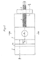
- la fig. 2 est une vue en coupe longitudinale faite suivant la ligne 11-il de la fig. 1,
- -la fig. 3 est une vue en coupe transversale faite suivant la ligne III-III de la fig. 1,
- la fig. 4 est une vue analogue à celle de la fig. 2 montrant une variante.
- fig. 1 is a plan view,
- fig. 2 is a view in longitudinal section taken along line 11-il of FIG. 1,
- - fig. 3 is a cross-sectional view taken along line III-III of FIG. 1,
- fig. 4 is a view similar to that of FIG. 2 showing a variant.
La dispositif représenté comporte de façon classique un corps 1 de mors fixe 1 a dans lequel sont aménagées des glissières 1 b qui guident le coulissement du mors mobile 2 sous l'action de la vis de serrage 3.The device shown conventionally comprises a
Toutefois celle-ci, au lieu d'être en prise avec le taraudage d'un orifice prévu dans une oreille du corps du mors fixe, est engagée et en prise avec le taraudage d'un orifice prévu dans une bride 4, reliée à une contre-bride 5 par des tirants 6 dans leur partie centrale, et par des barres de compression 7 à leur partie inférieure.However, the latter, instead of being engaged with the tapping of an orifice provided in an ear of the body of the fixed jaw, is engaged and engaged with the tapping of an orifice provided in a
Le mors fixe 1 prend appui sur la partie bombée 5a de la contre-bride 5, prévue dans l'axe de la vis de serrage 3, et la barre de compression sur son autre partie bombée 5b, symétrique de la précédente par rapport au tirant 6.The
En fait, comme le montre la fig. 3, il y a deux tirants 6, symétriques par rapport au plan de symétrie des mors fixe 1 et mobile 2 passant par l'axe de la vis de serrage, et deux barres de poussée 7 symétriques par rapport à ce même plan.In fact, as shown in fig. 3, there are two
Le plan contenant les barres de traction 6 se trouve entre le plan contenant les barres de compression 7 et l'axe de la vis de serrage 3. Ce plan se trouve à mi-distance du plan contenant les barres de compression 7 et de l'axe de la vis de serrage 3, sans constituer une obligation.The plane containing the
Les tirants 6 et barres de compression 7 ne sont soumis qu'à des forces axiales, et à aucun effort de flexion, et les brides 4 et 5 sont des pièces distinctes, courtes et massives, soumises à des forces.bien équilibrées; l'ensemble des déformations de ce dispositif provoque lors du serrage un libre coulissement axial des tirants 6 et des barres de compression 7; seule la partie bombée 5a de la contre-bride 5, sur laquelle prend appui le corps 1 du mors fixe 1 a, demeure dans sa position initiale.The
Dans ces conditions, quelle que soit la puissance de serrage, il n'y a aucune possibilité de déformation du corps 1 du mors fixe, qui n'est soumis à aucun effort de flexion.Under these conditions, whatever the clamping power, there is no possibility of deformation of the
Les tirants 6, qui peuvent être de faible diamètre puisqu'ils ne sont soumis qu'à des forces de traction, traversent librement des trous percés à cet effet dans le corps 1 du mors fixe; les barres de compression 7, soumises seulement à des forces de compression, traversent également librement des trous percés à cet effet dans le corps 1, mais tels qu'ils évitent toute possibilité de flambage.The
Dans le prolongement de la vis de serrage 3, un piston 8 est logé dans un orifice correspondant du mors mobile 2 et de la chape 9; celle-ci a une section droite en forme de H lui permettant de coulisser sur les glissières 1 b du corps 1 du mors fixe; l'extrémité 8a du piston 8 est inclinée de bas en haut d'arrière en avant, et elle prend appui sur une face 10, de même inclinaison, du mors mobile 2.In the extension of the
De la sorte, lors du début de serrage, le mors mobile 2 est appliqué contre les faces de guidage supérieures du coulissement du mors mobile 2 sur le corps 1 du mors fixe, et ensuite, par réaction, le piston 8 soulève la chape 9 et maintient donc son épaulement inférieur appliqué contre les faces de guidage inférieures du coulissement du mors mobile 2 sur le corps 1 du mors fixe.In this way, at the start of tightening, the
L'extrémité antérieure 8a du piston 8 portant contre la surface 10 de même inclinaison du mors mobile 2, la résultante des forces de poussée exercées par la vis de serrage 3 sur le mors mobile est axiale, et dirigée vers la partie bombée 5a de la bride 5 contre laquelle porte la partie arrière du corps du mors fixe 1 a.The front end 8a of the
Dans la variante représentée à la fig. 4, l'extrémité inclinée de la vis de serrage 3 est constituée par la chape 11, également en forme de H, qui diffère de la chape 9 en ce-qu'elle est constituée par un cylindre incliné, au lieu de l'être par un cylindre droit, comme la chape 9; sa face arrière comporte un méplat 11 a, sur lequel porte l'extrémité de la vis de serrage 3, et sa face antérieure inclinée 11 b coopère avec une face 10 de même inclinaison de l'orifice du mors mobile 2, dans lequel cette chape 11 peut librement coulisser, pour produire le même résultat que la face inclinée 8a du piston 8 coopérant avec la face 10 de même inclinaison du mors mobile 2 dans le mode de réalisation décrit ci-dessus.In the variant shown in FIG. 4, the inclined end of the
Pour éviter toutes possibilités de coincement, la vis de serrage 3 est engagée et en prise avec un écrou 12 monté à rotule dans la bride 4.To avoid any possibility of jamming, the
Dans certains cas où une moins grande précision est suffisante, la bride 5 peut être constituée par la partie arrière 13 du corps 1 du mors fixe 1 a, comme le montre également la fig. 4; elle est également soumise à la tension exercée par les tirants 6, contre-balançant les poussées exercées par la vis de serrage 3 et les barres de compression 7, comme l'est la bride 5 des fig. 1 à 3.In certain cases where less precision is sufficient, the flange 5 may be constituted by the
Ce sont alors les extrémités des tirants 6 du côté de la bride 4 qui sont montés à rotule en 6a, sur ladite bride 4, de même que les extrémités 7a des barres de compression 7, de façon à éviter tout risque de coincement de ces tirants 6 et barres de compression 7 dans les trous correspondants du corps 1 du mors 1 a.It is then the ends of the
Il est bien entendu que le mode de réalisation de l'invention qui a été décrit ci-dessus en référence au dessin annexé a été donné à titre purement indicatif et nullement limitatif:It is understood that the embodiment of the invention which has been described above with reference to the appended drawing has been given for purely indicative and in no way limitative:
Claims (11)
Priority Applications (1)
| Application Number | Priority Date | Filing Date | Title |
|---|---|---|---|
| AT80400237T ATE1885T1 (en) | 1979-02-20 | 1980-02-19 | DEVICE FOR HOLDING A WORKPIECE IN A CERTAIN POSITION TO A MACHINE TOOL ONTO WHICH IT CAN BE MOUNTED. |
Applications Claiming Priority (2)
| Application Number | Priority Date | Filing Date | Title |
|---|---|---|---|
| FR7904613A FR2449511A1 (en) | 1979-02-20 | 1979-02-20 | WORKPIECE SUPPORT FOR MACHINE TOOL MACHINING |
| FR7904613 | 1979-02-20 |
Publications (2)
| Publication Number | Publication Date |
|---|---|
| EP0015207A1 EP0015207A1 (en) | 1980-09-03 |
| EP0015207B1 true EP0015207B1 (en) | 1982-12-01 |
Family
ID=9222344
Family Applications (1)
| Application Number | Title | Priority Date | Filing Date |
|---|---|---|---|
| EP80400237A Expired EP0015207B1 (en) | 1979-02-20 | 1980-02-19 | Device for holding a workpiece in a certain position with respect to a machine-tool on which it can be fixed |
Country Status (6)
| Country | Link |
|---|---|
| US (1) | US4295641A (en) |
| EP (1) | EP0015207B1 (en) |
| JP (1) | JPS55150948A (en) |
| AT (1) | ATE1885T1 (en) |
| DE (1) | DE3061176D1 (en) |
| FR (1) | FR2449511A1 (en) |
Families Citing this family (24)
| Publication number | Priority date | Publication date | Assignee | Title |
|---|---|---|---|---|
| US4345750A (en) * | 1981-02-02 | 1982-08-24 | Glaser Hans F | Vise |
| CH652059A5 (en) * | 1983-04-22 | 1985-10-31 | Bobst Sa | DEVICE FOR CENTERING AND FIXING A TOOL IN A SUPPORT. |
| FR2559085B2 (en) * | 1984-02-02 | 1987-06-26 | Boucher Freres Sarl Ets | DEVICE FOR HOLDING A WORKPIECE IN A DETERMINED POSITION IN RELATION TO A MACHINE TOOL ON WHICH THIS DEVICE CAN BE FIXED |
| US4569509A (en) * | 1984-04-02 | 1986-02-11 | Johann Good | Vise, particularly a machine vise |
| DE3532490A1 (en) * | 1985-09-12 | 1987-03-19 | Kesel Georg Gmbh & Co Kg | TENSION DEVICE |
| US4759535A (en) * | 1986-05-31 | 1988-07-26 | Tamotsu Takasugi | Machine vice |
| FR2613968A1 (en) * | 1987-04-14 | 1988-10-21 | Perez Ets | Clamping vice, particularly for machine tools |
| DE3841527C1 (en) * | 1988-12-09 | 1990-06-13 | Peter 7293 Pfalzgrafenweiler De Schuele | |
| DE3927197A1 (en) * | 1989-08-17 | 1991-02-21 | Sta Co Mettallerzeugnisse Gmbh | CLAMPING DEVICE |
| FR2689797B1 (en) * | 1992-04-13 | 1994-07-22 | Evard Precision Sa | SELF-CENTERING VISE. |
| US5374041A (en) * | 1994-02-25 | 1994-12-20 | Kurt Manufacturing Company, Inc. | Vise |
| CA2471981C (en) * | 2003-06-23 | 2009-11-03 | Fablock Inc. | Precision vice |
| US8336867B1 (en) | 2006-09-01 | 2012-12-25 | Chick Workholding Solutions, Inc. | Workholding apparatus having a detachable jaw plate |
| US8454004B1 (en) | 2006-09-01 | 2013-06-04 | Chick Workholding Solutions, Inc. | Workholding apparatus having a movable jaw member |
| US8573578B1 (en) | 2006-09-01 | 2013-11-05 | Chick Workholding Solutions, Inc. | Workholding apparatus |
| US8109494B1 (en) * | 2006-09-01 | 2012-02-07 | Chick Workholding Solutions, Inc. | Workholding apparatus having a movable jaw member |
| US9227303B1 (en) | 2006-09-01 | 2016-01-05 | Chick Workholding Solutions, Inc. | Workholding apparatus |
| CN102039533A (en) * | 2010-12-24 | 2011-05-04 | 东莞市康捷塑胶模具有限公司 | Special gripper for location on cutting of thimble |
| TWI409141B (en) * | 2012-07-20 | 2013-09-21 | Lin Tseh Pei | Quick release device for a movable jaw of a vise |
| CN103894843A (en) * | 2012-12-25 | 2014-07-02 | 上海龙钰电梯配件有限公司 | Fixing device used for machining wedge-shaped elevator safety gear |
| CN103240692B (en) * | 2013-04-28 | 2016-04-27 | 天津长荣印刷设备股份有限公司 | A kind of quick plug-in clamping device and method of work thereof |
| US9352451B1 (en) | 2013-05-02 | 2016-05-31 | Chick Workholding Solutions, Inc. | Workholding apparatus |
| DE102015003662B3 (en) * | 2015-03-20 | 2016-06-23 | Ludwig Ehrhardt Gmbh | vice |
| CN105234506A (en) * | 2015-11-17 | 2016-01-13 | 重庆秋虹工贸有限公司 | Tapping machine |
Family Cites Families (9)
| Publication number | Priority date | Publication date | Assignee | Title |
|---|---|---|---|---|
| US1406981A (en) * | 1919-07-21 | 1922-02-21 | Matthew S Cumner | Vise |
| US2880638A (en) * | 1956-11-23 | 1959-04-07 | Lawrence A Muggli | Jaw-advancing, -alignment and -adjusting means for machine-tool vises |
| FR1234812A (en) * | 1959-05-20 | 1960-10-19 | perfected vice | |
| US3312461A (en) * | 1964-10-16 | 1967-04-04 | Glenn A Copron | Vise |
| US3397880A (en) * | 1966-05-10 | 1968-08-20 | Kurt Mfg Company | Vise clamp |
| GB1185702A (en) * | 1967-01-31 | 1970-03-25 | Carolyn Rosemary Soar | Improvements in or relating to Engineering Vices |
| GB1181398A (en) * | 1967-11-01 | 1970-02-18 | Kenneth Reginald Beetlestone | A New or Improved Vice |
| US4223879A (en) * | 1979-05-29 | 1980-09-23 | Kurt Manufacturing Co., Inc. | Machine tool vise |
| JPS5946745B2 (en) * | 1979-06-28 | 1984-11-14 | 保 高杉 | machine vise |
-
1979
- 1979-02-20 FR FR7904613A patent/FR2449511A1/en active Granted
-
1980
- 1980-02-19 AT AT80400237T patent/ATE1885T1/en active
- 1980-02-19 DE DE8080400237T patent/DE3061176D1/en not_active Expired
- 1980-02-19 EP EP80400237A patent/EP0015207B1/en not_active Expired
- 1980-02-20 JP JP1931180A patent/JPS55150948A/en active Pending
- 1980-02-20 US US06/122,867 patent/US4295641A/en not_active Expired - Lifetime
Also Published As
| Publication number | Publication date |
|---|---|
| US4295641A (en) | 1981-10-20 |
| DE3061176D1 (en) | 1983-01-05 |
| JPS55150948A (en) | 1980-11-25 |
| EP0015207A1 (en) | 1980-09-03 |
| ATE1885T1 (en) | 1982-12-15 |
| FR2449511B1 (en) | 1982-08-20 |
| FR2449511A1 (en) | 1980-09-19 |
Similar Documents
| Publication | Publication Date | Title |
|---|---|---|
| EP0015207B1 (en) | Device for holding a workpiece in a certain position with respect to a machine-tool on which it can be fixed | |
| FR2645699A1 (en) | COUPLING HOOK, PARTICULARLY FOR THE LOWER BARS OF A THREE POINT HITCH OF A TRACTOR | |
| FR2660708A1 (en) | ASSEMBLY PIECE FOR LONGIFORM ELEMENTS. | |
| FR2896727A1 (en) | FASTENING FOR A TOWING RING | |
| FR2716824A1 (en) | Bearing or bush extractor from shafts or housings | |
| FR2488212A1 (en) | STEEL BANDING CLIP APPARATUS | |
| FR2661000A1 (en) | SHEAR TESTING TESTING MACHINE. | |
| FR2559085A2 (en) | Device allowing a workpiece to be machined to be held in a predetermined position with respect to a machine tool upon which this device may be fixed | |
| EP0669431B1 (en) | Girder system | |
| FR2486436A1 (en) | Demountable work vice for bench - has base with two parallel rails to locate fixed jaw and guide screw driven jaw with rapid adjustment | |
| CA1105296A (en) | Pipe abutting machine for haying in waters of diverse depths | |
| FR2750376A1 (en) | Load carrier mounting for motor vehicle tow hitch | |
| CH669243A5 (en) | Articulated and pivoting coupling - uses device to axially move link pin | |
| EP0046830B1 (en) | Precision compass with articulated legs and rigid cross-bar | |
| FR2495569A1 (en) | Sail mounting for sail board - has clamping sleeve for boom gripping over mast (NL 01.07.82) | |
| EP0251870A2 (en) | Device for closing the circle of metallic spectacles | |
| CH664267A5 (en) | Wrist-watch strap with links slotted for inserts - has resilient fingers which define slots for clipping into grooves around rods paired within outer links | |
| EP0088854A2 (en) | Tension clamp | |
| EP0317462B1 (en) | Staple-removing device, and method for its manufacture | |
| FR2570796A1 (en) | Device for holding objects, especially tools | |
| FR2797795A3 (en) | Drive tool for cylindrical work piece such as pipe | |
| FR2535634A1 (en) | CLAMPING CLAMP WITH INTERCHANGEABLE PIECES | |
| FR2676723A1 (en) | Lifting clamp with automatically adjustable fulcrum | |
| FR2509644A1 (en) | BOLT CUTTING MACHINE | |
| FR2724703A1 (en) | Tool for separating poles on awnings |
Legal Events
| Date | Code | Title | Description |
|---|---|---|---|
| PUAI | Public reference made under article 153(3) epc to a published international application that has entered the european phase |
Free format text: ORIGINAL CODE: 0009012 |
|
| AK | Designated contracting states |
Designated state(s): AT BE CH DE FR GB IT LU NL SE |
|
| 17P | Request for examination filed | ||
| ITF | It: translation for a ep patent filed |
Owner name: NOTARBARTOLO & GERVASI S.R.L. |
|
| GRAA | (expected) grant |
Free format text: ORIGINAL CODE: 0009210 |
|
| AK | Designated contracting states |
Designated state(s): AT BE CH DE FR GB IT LU NL SE |
|
| REF | Corresponds to: |
Ref document number: 1885 Country of ref document: AT Date of ref document: 19821215 Kind code of ref document: T |
|
| REF | Corresponds to: |
Ref document number: 3061176 Country of ref document: DE Date of ref document: 19830105 |
|
| PGFP | Annual fee paid to national office [announced via postgrant information from national office to epo] |
Ref country code: SE Payment date: 19830131 Year of fee payment: 4 |
|
| PGFP | Annual fee paid to national office [announced via postgrant information from national office to epo] |
Ref country code: AT Payment date: 19830215 Year of fee payment: 4 |
|
| PGFP | Annual fee paid to national office [announced via postgrant information from national office to epo] |
Ref country code: LU Payment date: 19830216 Year of fee payment: 4 |
|
| PG25 | Lapsed in a contracting state [announced via postgrant information from national office to epo] |
Ref country code: LU Free format text: LAPSE BECAUSE OF NON-PAYMENT OF DUE FEES Effective date: 19830228 |
|
| PGFP | Annual fee paid to national office [announced via postgrant information from national office to epo] |
Ref country code: FR Payment date: 19840217 Year of fee payment: 5 |
|
| PG25 | Lapsed in a contracting state [announced via postgrant information from national office to epo] |
Ref country code: AT Effective date: 19840219 |
|
| PG25 | Lapsed in a contracting state [announced via postgrant information from national office to epo] |
Ref country code: SE Effective date: 19840220 |
|
| PGFP | Annual fee paid to national office [announced via postgrant information from national office to epo] |
Ref country code: NL Payment date: 19840229 Year of fee payment: 5 |
|
| PGFP | Annual fee paid to national office [announced via postgrant information from national office to epo] |
Ref country code: BE Payment date: 19840331 Year of fee payment: 5 |
|
| PGFP | Annual fee paid to national office [announced via postgrant information from national office to epo] |
Ref country code: DE Payment date: 19840406 Year of fee payment: 5 |
|
| PGFP | Annual fee paid to national office [announced via postgrant information from national office to epo] |
Ref country code: CH Payment date: 19840523 Year of fee payment: 5 |
|
| GBPC | Gb: european patent ceased through non-payment of renewal fee | ||
| PG25 | Lapsed in a contracting state [announced via postgrant information from national office to epo] |
Ref country code: CH Effective date: 19850228 Ref country code: BE Effective date: 19850228 |
|
| BERE | Be: lapsed |
Owner name: ETS BOUCHER FRERES S.A.R.L. Effective date: 19850219 |
|
| PG25 | Lapsed in a contracting state [announced via postgrant information from national office to epo] |
Ref country code: NL Effective date: 19850901 |
|
| NLV4 | Nl: lapsed or anulled due to non-payment of the annual fee | ||
| REG | Reference to a national code |
Ref country code: CH Ref legal event code: PL |
|
| PG25 | Lapsed in a contracting state [announced via postgrant information from national office to epo] |
Ref country code: DE Effective date: 19851101 |
|
| PG25 | Lapsed in a contracting state [announced via postgrant information from national office to epo] |
Ref country code: GB Effective date: 19881118 |
|
| PG25 | Lapsed in a contracting state [announced via postgrant information from national office to epo] |
Ref country code: FR Free format text: LAPSE BECAUSE OF NON-PAYMENT OF DUE FEES Effective date: 19891027 |
|
| REG | Reference to a national code |
Ref country code: FR Ref legal event code: ST |
|
| EUG | Se: european patent has lapsed |
Ref document number: 80400237.6 Effective date: 19850604 |
|
| PLBE | No opposition filed within time limit |
Free format text: ORIGINAL CODE: 0009261 |
|
| STAA | Information on the status of an ep patent application or granted ep patent |
Free format text: STATUS: NO OPPOSITION FILED WITHIN TIME LIMIT |